EP0550240B1 - Atomic frequency standard - Google Patents
Atomic frequency standard Download PDFInfo
- Publication number
- EP0550240B1 EP0550240B1 EP92311698A EP92311698A EP0550240B1 EP 0550240 B1 EP0550240 B1 EP 0550240B1 EP 92311698 A EP92311698 A EP 92311698A EP 92311698 A EP92311698 A EP 92311698A EP 0550240 B1 EP0550240 B1 EP 0550240B1
- Authority
- EP
- European Patent Office
- Prior art keywords
- frequency standard
- atomic frequency
- vapor
- gas cell
- microwave
- Prior art date
- Legal status (The legal status is an assumption and is not a legal conclusion. Google has not performed a legal analysis and makes no representation as to the accuracy of the status listed.)
- Expired - Lifetime
Links
Images


Classifications
-
- G—PHYSICS
- G04—HOROLOGY
- G04F—TIME-INTERVAL MEASURING
- G04F5/00—Apparatus for producing preselected time intervals for use as timing standards
- G04F5/14—Apparatus for producing preselected time intervals for use as timing standards using atomic clocks
-
- H—ELECTRICITY
- H03—ELECTRONIC CIRCUITRY
- H03L—AUTOMATIC CONTROL, STARTING, SYNCHRONISATION OR STABILISATION OF GENERATORS OF ELECTRONIC OSCILLATIONS OR PULSES
- H03L7/00—Automatic control of frequency or phase; Synchronisation
- H03L7/26—Automatic control of frequency or phase; Synchronisation using energy levels of molecules, atoms, or subatomic particles as a frequency reference
Definitions
- This invention relates generally to the field of frequency standards, and in particular, it concerns a miniaturized atomic frequency standard.
- an atomic frequency standard which comprises a gas cell, a vapor contained in said gas cell, an oscillator operable to generate a microwave signal, a microwave cavity connected to said oscillator and operative to couple said microwave signal to said vapor, a source of light positioned such that said light passes through said vapor, an optical detector operable to detect said light having passed through said vapor, and circuitry operable to control the frequency of said microwave signal in response to the amount of light having passed through said vapor; characterized in that said source of light comprises a laser diode, and said microwave cavity comprises a rectilinear resonator.
- Figure 1 is a schematic illustration of a cell type atomic frequency standard.
- Figure 2 is a plan view of a slow-wave helical exciter.
- Figure 3 is a plan view of an LC gap exciter.
- Figure 4 is a plan view of one embodiment of a microstrip exciter.
- Figure 5 is a cross sectional view of a second embodiment of a microstrip exciter.
- Figure 6 is a cross-sectional view of a V-groove microstrip exciter.
- Figure 7 is a cross-sectional view of a helical exciter illustrating a thermal insulating member with integral collimating lens and a dither signal conductor.
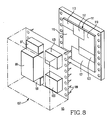
- Figure 8 is a schematic representation of the layout of an atomic frequency standard.
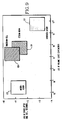
- Figure 9 is a graphical representation of the relative size and accuracy of an atomic frequency standard built in accordance with this invention when compared to prior art devices.
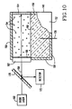
- Figure 10 illustrates a gas cell for an atomic frequency standard which also functions as the microwave resonator for the device.
- An atomic frequency standard operates by sensing transitions between two hyperfine levels of the ground state of an atom.
- Of particular interest are those atoms whose hyperfine levels are separated by routinely available microwave frequencies, and in particular, only two types have been extensively engineered - the cesium beam and the rubidium cell types.
- FIG. 1 is a schematic illustration of a cell type atomic frequency standard which is the subject of this invention.
- a crystal oscillator 1 is controlled to provide a stable frequency output signal 3.
- the output of the oscillator is also used to excite an alkali metal vapor 6 in a gas cell 5 which is located within a microwave cavity, preferably a rectilinear resonator 7.
- a source of light preferably a laser diode 9, is positioned to pass a beam of light 10 through the vapor 6 to an optical detector 11.
- the laser diode 9 is designed to provide light with a predetermined wavelength which will be absorbed by the vapor atoms in a ground state, causing them to move to an excited energy state.
- the resulting imbalance in the populations of the two hyperfine levels of the ground state provides a sensitivity to a microwave field.
- the output from the optical detector 11 is used as input for feedback control circuitry 13 which in turn produces a signal 14 for controlling the frequency of the oscillator 1 to the desired frequency.
- the resonator 7 is designed to be near or at resonance at the target frequency of the oscillator 1.
- An additional advantage is a reduction in the magnetic field sensitivity of the hyperfine transition.
- the only rigid constraint on the size of the gas cell of an atomic frequency standard is that it be compatible with the resonator design.
- the performance of a properly optimized device is expected to be a monotonic function of cell volume, for the following reasons.
- the short-term stability of a cell type frequency standard depends on the product of the Q of the hyperfine absorption line and the signal-to-noise ratio (S/N) of the detected optical signal. If the cell's volume is reduced, both of these factors tend to deteriorate. A decrease in the cell volume broadens the hyperfine absorption line through more rapid interaction of the vapor atoms with the cell walls. This effect can be mitigated by an increase in the buffer gas density, however, the accompanying collisional quenching limits this mitigation.
- the S/N ratio is normally determined by the optical shot noise and is therefore expected to vary as the square root of the optical signal strength. This varies monotonically with the total number of atoms available for pumping, and thus will decrease as the cell's volume decreases. Increasing the vapor atom density by raising the pressure/temperature can partially restore the S/N, limited by the accompanying line broadening from the increased collisional interaction rate. Hence, despite optimization of the buffer gas and vapor densities, reduction of the cell volume will carry a performance penalty, due to reduced line Q and reduced S/N.
- Inexpensive laser diodes can be operated single mode, such that essentially all of the optical power lies within a frequency band much narrower than the absorption line being pumped, thereby providing highly selective and intense pumping. Additional benefits from using a laser diode include reduced space requirement and simplified optical coupling from the source to the cell and detector. However, use of a diode laser in an atomic frequency standard requires that the laser be tuned to the relevant absorption line center, and and only a limited tuning range is achievable by varying the current and/or temperature of commercially available laser diodes having an internal cavity.
- the diode laser wavelength For an atomic frequency standard the diode laser wavelength must be stabilized indefinitely with a feedback control system to one of the absorption minima frequencies. With the laser diode temperature stabilized at a suitable value, the output can be frequency modulated by imposing a small alternating current component on the laser drive current. This causes a frequency modulation of the optical output, and it permits phase sensitivity detection of the resulting alternating current variations in the optical power transmitted through the gas cell. With this arrangement it is possible to lock the laser frequency to an absorption dip frequency for indefinite periods of time.
- Measurements of the bipolar error signal fluctuations indicate that a diode laser can be stabilized to approximately 100 KHz when the alternating current amplitude is 30 microamps, corresponding to an alternating current frequency of 25 MHz, using a pressure-broadened absorption peak having a width between inflection points of 1.1 GHz. This stability is more than adequate for the present purpose.
- An example of this technique is described in more detail in an article by T. M. Shay and Yun C. Chung entitled 400 Hz Frequency Stability of a GaAlAs Laser Frequency Locked to the Rb(D 2 ) Line , published in Optical Engineering, Volume 29, Number 6, June 1990, herein incorporated by reference.
- the object of this invention necessitates a microwave cavity 7 with minimum dimensions.
- One possibility is illustrated by the slow-wave helical exciter 15 of Figure 2.
- This design consists of a gas cell 17 with a conductor 19 formed around its outside surface.
- the conductor 19 can be in contact with the surface of the gas cell 17 or sufficiently near the gas cell 17 to operatively couple a signal carried by the conductor 19 to the vapor (not shown) within the gas cell 17.
- the conductor 19 can be formed as a helix, with design parameters selected so as to support a standing or running wave when coupled to an input signal of the desired frequency.
- the circumference of the gas cell 17 should be limited to no more than one-half the wavelength of the signal, in order to maintain the coil as non-radiating, thereby increasing the efficiency of the coupling of the signal to the vapor within the gas cell 17.
- the conductor 19 can be formed by winding wire onto the outside of the gas cell 17, or a tape helix can be formed by depositing a metal coating onto the entire outer surface of the gas cell 17 and then selectively removing metal by etching to form the desired conductor shape.
- the helical exciter's loaded Q is comparable to that of a rectangular cavity (approximately 80), but it is more difficult to tune.
- the H field pattern within the coil has radial and axial components, with the latter having a minimum on the axis where one would prefer it to be strongest. Nevertheless, measurements have shown that this type of exciter is useful in an atomic frequency standard application.
- the size of the gas cell 17 being minimized such that its circumference is no more than one-half the wavelength of the input signal, a fraction of a microwatt is sufficient power to provide the necessary field penetration for excitation of the contained vapor. This power level can be conveniently provided by MOS circuitry.
- the gas cell 17 preferably has outside dimensions of no more than 6 mm diameter by 18 mm length, and an internal volume of no more than 100 cubic millimeters.
- the container may also serve as a shield for the helix as is known in traveling wave tube art.
- Excitation of the conductor 19 may be accomplished by a second, short, bifilar helix 21 wound at the input and/or output of the main conductor helix 19.
- the bifilar helix windings 21 may serve as a heater as part of a temperature control system for the gas cell 17.
- a temperature control system would utilize a temperature sensor 23, which is located either within the volume of the gas cell 17 or on its surface.
- the main conductor helix 19 may also serve as a heater, which may involve pitch changes leading to a filter helix.
- LC gap exciter 27 of Figure 3 An alternative miniature microwave exciter design is illustrated by the LC gap exciter 27 of Figure 3, where an LC gap conductor 29 is formed on or around a gas cell 31.
- the LC gap conductor 29 is operable to carry the digital signal from the oscillator of an atomic frequency standard, and it serves to provide an efficient electromagnetic coupling to the vapor (not shown) contained within gas cell 31.
- a rectilinear resonator is preferred, for example a rectangular TE 101 cavity loaded with a low loss dielectric.
- the microstrip exciter 35 of Figure 4 can be used.
- a ground plane 37 and a conducting strip 39 are separated by a dielectric material 41.
- the conducting strip 39 is operable to carry the signal from the oscillator of an atomic frequency standard, which is provided at input connection 43 and is inductively coupled to the conducting strip 39.
- the conducting strip 39 is preferably at or near a resonant length for a signal at the target frequency.
- microstrip exciter 35 acts as a conventional microstrip resonator, are coupled electromagnetically to a gas cell 45 which contains an alkali vapor 47.
- the gas cell 45 is a sealed container positioned in a channel formed in the dielectric material 41. Because the wavelength of the signal passing through the dielectric material is appreciably shorter than the wavelength of the signal passing through vapor, the overall size of the microstrip exciter 35 is significantly smaller than prior art resonant cavity designs.
- the microstrip exciter 35 of Figure 4 can be designed using calculational techniques known in the art for modelling the effects of electromagnetic radiation. For a target frequency of 9.19 GHz, a line impedance of 50 ohms, and a dielectric material constant of 4; the approximate size of a microstrip exciter 35 is 10 mm in length, 9 mm in width, and 5 mm in height, with corresponding gas cell dimensions of 3 mm width, 3 mm height and 10 mm length.
- the length of the gas cell 45 is preferably the same as a half wavelength conducting strip 39. Use of a shorter length is acceptable, but cells significantly longer than a half wavelength have the disadvantage that the additional length is not subjected to the higher electromagnetic fields associated with the resonant section.
- the microstrip exciter 35 of Figure 4 is fabricated using fabrication techniques which are known in the art.
- the materials of construction of the microstrip exciter 35 can vary to accommodate different design frequencies and dimensional limitations.
- the ground plane 37 and resonant length conducting strip 39 are conductors, such as copper or gold.
- the gas cell 45 and the dielectric material 41 can be made from one piece of bulk material, or the gas cell 45 can be a separate piece inserted into a hole bored into the length of the dielectric material 41.
- the dielectric material is typically glass or sapphire, or quartz. If the gas cell 45 and dielectric material 41 are one piece quartz, the quartz must be lined with a suitable coating to prevent attack by the alkali vapor.
- the materials of construction interact with other variables in the design to affect the overall dimensions of the microstrip exciter 35. For example, increasing the dielectric constant has the effect of decreasing the wavelength and the characteristic impedance, thereby reducing the size of the component.
- FIG. 5 illustrates a cross sectional view of another embodiment of a microstrip exciter 51.
- the microstrip exciter 51 has a gas cell 53 containing a vapor 55 positioned on top of a conducting strip 57.
- a dielectric material 59 separates the conducting strip 57 from the ground plane 61.
- Microwave power is provided to the conducting strip 57 through input conductor 63.
- the electromagnetic field in this device consists of closed loops of energy surrounding the conducting strip 57. While the intensity of the field is maximized in the area between the conducting strip 57 and the ground plane 61, some of the field lines do pass through the position of the gas cell 53, thus providing the required electromagnetic coupling.
- the gas cell 53 can be placed directly on the conducting strip 57 or located sufficiently near to operatively couple the signal to the vapor 55. Coupling efficiency for this type of device can be improved if the conducting strip and dielectric material are shaped to have the form of a V-groove, with the gas cell positioned in the valley of the V-groove.
- Figure 6 illustrates this type of V-groove microstrip exciter 67, which consists of a ground plane 69, dielectric material 71, a conducting strip 73 which is in the shape of a V-groove, and a gas cell 75.
- a description of V-groove microstrip line is contained in Characteristics of Valley Microstrip Lines for use in Multilayer MMIC's by T. Hasegawa, S. Banba, H. Ogawa, and H. Nakamoto, published IEEE Microwave and Guided Wave Letters, Volume 1, Number 10, October 1991, incorporated by reference herein.
- Temperature stability of the vapor in an atomic frequency standard is important for maintaining the accuracy of the frequency.
- a gas cell 79 containing alkali vapor 81 is surrounded by a thermally insulating member 83, which can be formed from glass or other material capable of transmitting light from an external source of light (not shown).
- the thermally insulating member 83 can be sealed and a vacuum applied to evacuate the space between the insulating member 83 and the gas cell 79.
- the thermally insulating member 83 serves to isolate the gas cell 79 from temperature changes in the external environment.
- a temperature control device 85 can be positioned within the thermally insulating member 83 to sense and/or to control the temperature within the volume of the thermally insulating member 83.
- a helical conductor 87 may be formed on the gas cell 79 to provide coupling with the microwave signal, or alternatively, a helical conductor 89 may be formed on the thermally insulating member 83 if sufficient coupling can be obtained.
- a further adaptation of this concept is to form one or more collimating lens 91 as an integral part of the thermally insulating member 83. Such a collimating lens 91 would serve to focus the light passing through the alkali vapor 81 contained within the gas cell 79.
- the frequency might be varied for use in a stabilization dither circuit.
- This effect can be produced by providing a conductor 93 as illustrated in Figure 7. Voltage and current dither signals applied to the conductor 93 will induce electric and magnetic fields in the vapor 81. These fields, in turn, will produce minor changes in the fundamental transition frequency of the vapor, thereby producing a dither in the target frequency of the atomic frequency standard.
- This technique can also be used as part of temperature compensation circuitry whereby the signals carried by the conductor 93 are responsive to temperature variations and they serve to negate changes in the output. frequency of the atomic frequency standard resulting from changes in temperature.
- the crystal oscillator 1 of Figure 1 is preferably replaced by a high overtone bulk acoustic resonator (HBAR), such as that taught in U.S. Patent No. 4,785,269 entitled "Magnetically Tuned High Overtone Bulk Acoustic Resonator” issued to Adam, et al, incorporated by reference herein.
- HBAR high overtone bulk acoustic resonator
- the function of the optical detector 11 of Figure 1 is preferably performed by a silicon PIN diode, also formed on the common semiconductor substrate.
- the function of the source of light 9 of Figure 1 is provided by a diode laser. Commercially available diode lasers are prepackaged and can be affixed to a semiconductor substrate or mounted as a discrete component.
- the microwave digital and analog control circuits required for the atomic frequency standard can be combined on a single gallium arsenide semiconductor wafer using techniques known in the art. Alternatively, a silicon semiconductor wafer can be utilized to reduce the cost of the device.
- FIG 8 is a schematic representation of the layout of an atomic frequency standard 95 embodying this invention.
- a laser diode light source 97, a miniaturized cesium gas cell and microwave exciter 99, PIN diode optical detector 101, HBAR oscillator 103, and power modules 105 are mounted in a constant temperature housing 107, which can measure approximately 2 cm by 3 cm by 1 cm.
- These components are connected by connectors 109 to a semiconductor substrate 111 upon which are fabricated the circuits for laser drive 113, microwave drive 115, voltage controlled oscillator 117, frequency control 119, and temperature control 121.
- Output circuitry 123 can also be included to convert the frequency standard signal to a measure of time.
- the entire volume of an atomic frequency standard built in accordance with this invention can be less than 12 cubic centimeters.
- the stability of such a device can be on the order of 4-6 X 10 -12 for a one second averaging time.
- Figure 9 illustrates how the combination of size and accuracy of this invention 127 relates to the size and accuracy of prior art devices such as a rubidium cell device 129, cesium beam device 131, and a hydrogen maser 133.
- An atomic frequency standard built in accordance with this invention provides a reduction in size on the order of two orders of magnitude without a loss of stability, thus representing a significant advancement in the art of atomic frequency standards.
- a frequency standard may be desired in the shape of a pocket calculator or a thick credit card.
- a gas cell which also functions as a microwave resonator, so that the resonator and gas cell are a single container.
- Figures 10 illustrates one embodiment of such a container 149, where a rectilinear gas cell is formed by a metal container having side walls 150, top plate 152 (partially cut away), and a bottom plate (not shown).
- the gas cell Since the gas cell is a metallic structure, it can function both to contain the vapor 154 and to act as a resonator for the microwave energy introduced into the gas cell through a microwave probe 156 or other microwave coupling device. Designing such a gas cell as a TE 101 rectilinear resonator to minimize one dimension using known calculational techniques can result in the thickness of the resonator being no more than 6 mm.
- a window 162 which may be a transparent or semi-transparent member.
- the light 158 entering the gas cell may pass out of the gas cell through a second window, or alternatively, a mirror 164, mirrored surface or other means for reflecting the light may be provided to return the light 158 back through the window 162.
- a screen or semi-transparent conductor 166 may be placed on the window 162 to enhance the cavity Q.
- a dielectric material 168 may be placed within the gas cell to tune the microwave resonance of the cavity.
- a beam splitter 170 may be positioned to direct the returned light to a detector 172.
- the container structure including the walls 150, top plate 152, and bottom plate (not shown) can be made of or plated with a metal, such as nickel or chromium, which does not react or alloy with the vapor 154, typically cesium.
- Borosilicate glasses such as pyrex and sapphire are typical inert window materials which may be used. The choice of materials must be made to permit a hermetic seal to be formed between the walls and the windows.
- One such combination is niobium or tantalum metal joined to sapphire.
Landscapes
- Physics & Mathematics (AREA)
- Spectroscopy & Molecular Physics (AREA)
- General Physics & Mathematics (AREA)
- Stabilization Of Oscillater, Synchronisation, Frequency Synthesizers (AREA)
Applications Claiming Priority (4)
| Application Number | Priority Date | Filing Date | Title |
|---|---|---|---|
| US07/815,677 US5192921A (en) | 1991-12-31 | 1991-12-31 | Miniaturized atomic frequency standard |
| US815677 | 1991-12-31 | ||
| US07/966,209 US5327105A (en) | 1991-12-31 | 1992-10-26 | Gas cell for a miniaturized atomic frequency standard |
| US966209 | 1992-10-26 |
Publications (2)
| Publication Number | Publication Date |
|---|---|
| EP0550240A1 EP0550240A1 (en) | 1993-07-07 |
| EP0550240B1 true EP0550240B1 (en) | 1998-08-26 |
Family
ID=27123986
Family Applications (1)
| Application Number | Title | Priority Date | Filing Date |
|---|---|---|---|
| EP92311698A Expired - Lifetime EP0550240B1 (en) | 1991-12-31 | 1992-12-22 | Atomic frequency standard |
Country Status (7)
| Country | Link |
|---|---|
| US (1) | US5327105A (enExample) |
| EP (1) | EP0550240B1 (enExample) |
| JP (1) | JPH05300016A (enExample) |
| CA (1) | CA2086021A1 (enExample) |
| IL (1) | IL104226A (enExample) |
| MX (1) | MX9207305A (enExample) |
| TW (1) | TW248597B (enExample) |
Cited By (14)
| Publication number | Priority date | Publication date | Assignee | Title |
|---|---|---|---|---|
| DE102021113199A1 (de) | 2021-05-20 | 2022-11-24 | Endress+Hauser SE+Co. KG | Remote Sensoranordnung |
| DE102021113201A1 (de) | 2021-05-20 | 2022-11-24 | Endress+Hauser SE+Co. KG | Remote Kommunikationsanordnung |
| DE102021113200A1 (de) | 2021-05-20 | 2022-11-24 | Endress+Hauser SE+Co. KG | Detektion paramagnetischer Stoffe in Fluiden |
| DE102021113369A1 (de) | 2021-05-21 | 2022-11-24 | Endress+Hauser Conducta Gmbh+Co. Kg | pH-Sensor |
| DE102021113198A1 (de) | 2021-05-20 | 2022-11-24 | Endress + Hauser Wetzer Gmbh + Co. Kg | In situ Temperatur Kalibration |
| DE102021117837A1 (de) | 2021-07-09 | 2023-01-12 | Endress+Hauser Conducta Gmbh+Co. Kg | Leitfähigkeitssensor |
| DE102021117833A1 (de) | 2021-07-09 | 2023-01-12 | Endress+Hauser Flowtec Ag | Leitfähigkeitssensor |
| WO2023016775A1 (de) | 2021-08-11 | 2023-02-16 | Analytik Jena Gmbh | Vorrichtung für die analyse einer als tropfen bereitgestellten flüssigen oder pastösen probe anhand von kernspinresonanzen der probe |
| DE102021120976A1 (de) | 2021-08-11 | 2023-02-16 | Analytik Jena Gmbh | Mikrotiterplatte |
| DE102021120975A1 (de) | 2021-08-11 | 2023-02-16 | Analytik Jena Gmbh | Reaktionsgefäß für die Analyse einer flüssigen oder pastösen Probe anhand ihrer Kernspinresonanzen |
| DE102021120973A1 (de) | 2021-08-11 | 2023-02-16 | Analytik Jena Gmbh | Küvette für die Analyse einer als Tropfen bereitgestellten flüssigen oder pastösen Probe anhand von Kernspinresonanzen der Probe |
| DE102021120974A1 (de) | 2021-08-11 | 2023-02-16 | Endress+Hauser Flowtec Ag | Inline-Messgerät für die Analyse eines Mediums |
| DE102021134246A1 (de) | 2021-12-22 | 2023-06-22 | Endress + Hauser Flowtec Ag | Mikrowellenmessvorrichtung |
| DE102021134237A1 (de) | 2021-12-22 | 2023-06-22 | Endress+Hauser Flowtec Ag | Vorrichtung zur Analyse von Verunreinigungen oder Fremdkörpern |
Families Citing this family (54)
| Publication number | Priority date | Publication date | Assignee | Title |
|---|---|---|---|---|
| US5517157A (en) * | 1993-04-27 | 1996-05-14 | Ball Corporation | Evanescent-field interrogator for atomic frequency standards |
| US5420826A (en) * | 1993-10-18 | 1995-05-30 | Westinghouse Electric Corp. | Optical correlator and method of using same |
| US5442326A (en) * | 1994-09-09 | 1995-08-15 | Westinghouse Electric Corporation | Atomic time standard with piezoelectric stabilization of diode laser light source |
| US5656189A (en) * | 1994-12-02 | 1997-08-12 | Efratom Time And Frequency Products, Inc. | Heater controller for atomic frequency standards |
| US5489821A (en) * | 1994-12-27 | 1996-02-06 | Ball Corporation | Lamp oscillator for atomic frequency standards |
| US5670914A (en) * | 1995-09-25 | 1997-09-23 | Northrop Grumman Corporation | Miniature atomic frequency standard |
| EP0911919A1 (en) * | 1995-09-29 | 1999-04-28 | Observatoire Cantonal De Neuchatel | Atomic frequency standard |
| US5657340A (en) * | 1996-04-19 | 1997-08-12 | The Aerospace Corporation | Rubidium atomic clock with fluorescence optical pumping and method using same |
| US5896105A (en) * | 1997-06-23 | 1999-04-20 | Northrop Grumman Corporation | Distributed phased array antenna system |
| US6320472B1 (en) | 1999-01-26 | 2001-11-20 | Kernco, Inc. | Atomic frequency standard |
| US6215366B1 (en) * | 1999-05-05 | 2001-04-10 | Kernco, Inc. | Metallic cell for optically activated atomic frequency standards |
| US6265945B1 (en) * | 1999-10-25 | 2001-07-24 | Kernco, Inc. | Atomic frequency standard based upon coherent population trapping |
| US6426679B1 (en) | 2000-12-14 | 2002-07-30 | Northrop Grumman Corporation | Miniature, low power atomic frequency standard with improved rf frequency synthesizer |
| US6806784B2 (en) | 2001-07-09 | 2004-10-19 | The National Institute Of Standards And Technology | Miniature frequency standard based on all-optical excitation and a micro-machined containment vessel |
| US6831522B2 (en) | 2001-07-09 | 2004-12-14 | The United States Of America As Represented By The Secretary Of Commerce | Method of minimizing the short-term frequency instability of laser-pumped atomic clocks |
| US6643311B2 (en) * | 2001-10-23 | 2003-11-04 | William F. Krupke | Diode-pumped alkali laser |
| US6570459B1 (en) * | 2001-10-29 | 2003-05-27 | Northrop Grumman Corporation | Physics package apparatus for an atomic clock |
| JP3811079B2 (ja) * | 2002-02-05 | 2006-08-16 | 富士通株式会社 | 原子発振器 |
| AU2003209901A1 (en) | 2002-03-19 | 2003-09-29 | Dicos Technologies Inc. | Metallic gas cells and method for manufacturing the same |
| US6919770B2 (en) * | 2003-03-11 | 2005-07-19 | Princeton University | Method and system for operating an atomic clock with reduced spin-exchange broadening of atomic clock resonances |
| US20050007118A1 (en) * | 2003-04-09 | 2005-01-13 | John Kitching | Micromachined alkali-atom vapor cells and method of fabrication |
| US7064835B2 (en) * | 2003-09-02 | 2006-06-20 | Symmetricom, Inc. | Miniature gas cell with folded optics |
| DE10355866B3 (de) * | 2003-11-27 | 2005-04-14 | Jenoptik Laser, Optik, Systeme Gmbh | Optische Anordnung zur Gewinnung eines Messsignals für die Leistungsmessung bei Lasern |
| US7400207B2 (en) * | 2004-01-06 | 2008-07-15 | Sarnoff Corporation | Anodically bonded cell, method for making same and systems incorporating same |
| CN100580584C (zh) | 2005-07-21 | 2010-01-13 | 精工爱普生株式会社 | 便携式钟表以及电子设备 |
| DE602006021749D1 (de) * | 2005-07-21 | 2011-06-16 | Seiko Epson Corp | Tragbare uhr und elektronische einrichtung |
| JP4605508B2 (ja) * | 2005-12-28 | 2011-01-05 | セイコーエプソン株式会社 | 原子周波数取得装置および原子時計 |
| JP2009129955A (ja) * | 2007-11-20 | 2009-06-11 | Epson Toyocom Corp | 光学系及び原子発振器 |
| US7893780B2 (en) * | 2008-06-17 | 2011-02-22 | Northrop Grumman Guidance And Electronic Company, Inc. | Reversible alkali beam cell |
| JP5375279B2 (ja) | 2008-06-18 | 2013-12-25 | セイコーエプソン株式会社 | 原子発振器 |
| WO2010022881A1 (en) * | 2008-08-29 | 2010-03-04 | Exxonmobil Chemical Patents Inc. | Hydroformylation process including catalyst recycle |
| WO2011026252A1 (fr) | 2009-09-04 | 2011-03-10 | Csem Centre Suisse D'electronique Et De Microtechnique S.A. | Dispositif pour horloge atomique |
| WO2011026251A1 (fr) | 2009-09-04 | 2011-03-10 | Csem Centre Suisse D'electronique Et De Microtechnique S.A. | Dispositif pour horloge atomique |
| CH703111A1 (fr) * | 2010-05-07 | 2011-11-15 | Suisse Electronique Microtech | Dispositif pour horloge atomique. |
| EP2498150A1 (fr) | 2011-03-09 | 2012-09-12 | CSEM Centre Suisse D'electronique Et De Microtechnique SA | Horloge atomique |
| US8756976B2 (en) | 2011-09-13 | 2014-06-24 | Honeywell International Inc. | Systems and methods for gettering an atomic sensor |
| US8854146B2 (en) | 2012-01-31 | 2014-10-07 | Honeywell International Inc. | Systems and methods for external frit mounted components |
| EP2629158A1 (en) * | 2012-02-16 | 2013-08-21 | Université de Neuchâtel | Microwave resonator, quantum sensor, and atomic clock |
| US9285249B2 (en) | 2012-10-04 | 2016-03-15 | Honeywell International Inc. | Atomic sensor physics package with metal frame |
| US9249656B2 (en) | 2012-11-15 | 2016-02-02 | Baker Hughes Incorporated | High precision locked laser operating at elevated temperatures |
| JP6119294B2 (ja) * | 2013-02-18 | 2017-04-26 | セイコーエプソン株式会社 | 量子干渉装置、原子発振器および移動体 |
| JP5713039B2 (ja) * | 2013-03-04 | 2015-05-07 | セイコーエプソン株式会社 | 原子発振器 |
| US9410885B2 (en) | 2013-07-22 | 2016-08-09 | Honeywell International Inc. | Atomic sensor physics package having optically transparent panes and external wedges |
| US9312869B2 (en) * | 2013-10-22 | 2016-04-12 | Honeywell International Inc. | Systems and methods for a wafer scale atomic clock |
| CN106104396B (zh) * | 2014-02-06 | 2019-09-13 | 奥罗利亚瑞士股份公司 | 用于原子钟的装置 |
| US9429918B2 (en) * | 2014-06-20 | 2016-08-30 | Texas Instruments Incorporated | Atomic clocks and magnetometers with vapor cells having condensation sites in fluid communication with a cavity to hold a vapor condensation away from an optical path |
| CN105762643B (zh) * | 2016-04-19 | 2019-02-19 | 中国科学院电子学研究所 | 一种双层结构的碱金属蒸气室 |
| CN107229213B (zh) * | 2016-12-14 | 2019-12-06 | 北京无线电计量测试研究所 | 一种用于小型氢原子钟的蓝宝石加载微波腔 |
| US10649408B2 (en) | 2017-12-29 | 2020-05-12 | Texas Instruments Incorporated | Molecular atomic clock with wave propagating rotational spectroscopy cell |
| US10859980B2 (en) * | 2017-12-29 | 2020-12-08 | Texas Instruments Incorporated | Molecular atomic clock with wave propagating rotational spectroscopy cell |
| US10754302B2 (en) | 2017-12-29 | 2020-08-25 | Texas Instruments Incorporated | Molecular atomic clock with wave propagating rotational spectroscopy cell |
| US11180844B2 (en) | 2018-07-02 | 2021-11-23 | Government Of The United States Of America, As Represented By The Secretary Of Commerce | Process for making alkali metal vapor cells |
| US11899406B2 (en) | 2020-01-07 | 2024-02-13 | The Regents Of The University Of Colorado, A Body Corporate | Devices, systems, and methods for fabricating alkali vapor cells |
| RU2747165C1 (ru) * | 2020-06-16 | 2021-04-28 | Общество с ограниченной ответственностью «Атомикс» (ООО «Атомикс») | Квантовый стандарт частоты с лазерной оптической накачкой |
Family Cites Families (11)
| Publication number | Priority date | Publication date | Assignee | Title |
|---|---|---|---|---|
| US3248666A (en) * | 1963-03-12 | 1966-04-26 | Gtc Kk | Optically pumped combination gas cell and microwave resonating cavity |
| US4425653A (en) * | 1980-07-01 | 1984-01-10 | Hewlett-Packard Company | Atomic beam device using optical pumping |
| US4462006A (en) * | 1981-07-20 | 1984-07-24 | Rockwell International Corporation | Method for stabilizing the resonance frequency of a rubidium frequency standard |
| US4494085A (en) * | 1982-04-28 | 1985-01-15 | Eg&G, Inc. | Miniaturized atomic frequency standard having both filter cell and absorption cell in resonator cavity |
| US4476445A (en) * | 1982-05-18 | 1984-10-09 | Eg&G, Inc. | Methods and apparatus for rapid and accurate frequency syntonization of an atomic clock |
| US4495478A (en) * | 1983-02-16 | 1985-01-22 | Litton Systems, Inc. | Cavity resonator for atomic frequency standard |
| US4482259A (en) * | 1983-05-26 | 1984-11-13 | The United States Of America As Represented By The Secretary Of The Air Force | Laser clock |
| US4961119A (en) * | 1986-05-23 | 1990-10-02 | Irish Ernest E | Harmonic optical oscillator |
| FR2627909A1 (fr) * | 1988-02-29 | 1989-09-01 | Oscilloquartz Sa | Etalon de frequence passif |
| FR2628226B1 (fr) * | 1988-03-03 | 1991-06-07 | Rech Const Electro Et | Horloge atomique |
| JPH0783265B2 (ja) * | 1989-08-21 | 1995-09-06 | 新技術事業団 | レーザ励起ルビジウム原子発振器 |
-
1992
- 1992-10-26 US US07/966,209 patent/US5327105A/en not_active Expired - Lifetime
- 1992-12-12 TW TW081109975A patent/TW248597B/zh active
- 1992-12-16 MX MX9207305A patent/MX9207305A/es unknown
- 1992-12-22 EP EP92311698A patent/EP0550240B1/en not_active Expired - Lifetime
- 1992-12-22 CA CA002086021A patent/CA2086021A1/en not_active Abandoned
- 1992-12-24 JP JP4357461A patent/JPH05300016A/ja not_active Withdrawn
- 1992-12-24 IL IL10422692A patent/IL104226A/en not_active IP Right Cessation
Cited By (21)
| Publication number | Priority date | Publication date | Assignee | Title |
|---|---|---|---|---|
| DE102021113201A1 (de) | 2021-05-20 | 2022-11-24 | Endress+Hauser SE+Co. KG | Remote Kommunikationsanordnung |
| DE102021113200A1 (de) | 2021-05-20 | 2022-11-24 | Endress+Hauser SE+Co. KG | Detektion paramagnetischer Stoffe in Fluiden |
| DE102021113198A1 (de) | 2021-05-20 | 2022-11-24 | Endress + Hauser Wetzer Gmbh + Co. Kg | In situ Temperatur Kalibration |
| WO2022242973A1 (de) | 2021-05-20 | 2022-11-24 | Endress+Hauser Wetzer Gmbh+Co. Kg | In situ temperatur kalibration |
| WO2022243120A1 (de) | 2021-05-20 | 2022-11-24 | Endress+Hauser SE+Co. KG | Remote sensoranordnung |
| DE102021113199A1 (de) | 2021-05-20 | 2022-11-24 | Endress+Hauser SE+Co. KG | Remote Sensoranordnung |
| US11906452B2 (en) | 2021-05-21 | 2024-02-20 | Endress+Hauser Conducta Gmbh+Co. Kg | PH-sensor for determining and/or measuring a pH-value of a medium |
| DE102021113369A1 (de) | 2021-05-21 | 2022-11-24 | Endress+Hauser Conducta Gmbh+Co. Kg | pH-Sensor |
| DE102021117837A1 (de) | 2021-07-09 | 2023-01-12 | Endress+Hauser Conducta Gmbh+Co. Kg | Leitfähigkeitssensor |
| DE102021117833A1 (de) | 2021-07-09 | 2023-01-12 | Endress+Hauser Flowtec Ag | Leitfähigkeitssensor |
| WO2023280748A1 (de) | 2021-07-09 | 2023-01-12 | Endress+Hauser Flowtec Ag | Leitfähigkeitssensor |
| WO2023016775A1 (de) | 2021-08-11 | 2023-02-16 | Analytik Jena Gmbh | Vorrichtung für die analyse einer als tropfen bereitgestellten flüssigen oder pastösen probe anhand von kernspinresonanzen der probe |
| DE102021120975A1 (de) | 2021-08-11 | 2023-02-16 | Analytik Jena Gmbh | Reaktionsgefäß für die Analyse einer flüssigen oder pastösen Probe anhand ihrer Kernspinresonanzen |
| DE102021120973A1 (de) | 2021-08-11 | 2023-02-16 | Analytik Jena Gmbh | Küvette für die Analyse einer als Tropfen bereitgestellten flüssigen oder pastösen Probe anhand von Kernspinresonanzen der Probe |
| WO2023016776A1 (de) | 2021-08-11 | 2023-02-16 | Analytik Jena Gmbh | Mikrotiterplatte |
| DE102021120972A1 (de) | 2021-08-11 | 2023-02-16 | Analytik Jena Gmbh | Vorrichtung für die Analyse einer als Tropfen bereitgestellten flüssigen oder pastösen Probe anhand von Kernspinresonanzen der Probe |
| DE102021120974A1 (de) | 2021-08-11 | 2023-02-16 | Endress+Hauser Flowtec Ag | Inline-Messgerät für die Analyse eines Mediums |
| DE102021120976A1 (de) | 2021-08-11 | 2023-02-16 | Analytik Jena Gmbh | Mikrotiterplatte |
| DE102021134246A1 (de) | 2021-12-22 | 2023-06-22 | Endress + Hauser Flowtec Ag | Mikrowellenmessvorrichtung |
| DE102021134237A1 (de) | 2021-12-22 | 2023-06-22 | Endress+Hauser Flowtec Ag | Vorrichtung zur Analyse von Verunreinigungen oder Fremdkörpern |
| WO2023117258A1 (de) | 2021-12-22 | 2023-06-29 | Endress+Hauser Flowtec Ag | Mikrowellenmessvorrichtung |
Also Published As
| Publication number | Publication date |
|---|---|
| US5327105A (en) | 1994-07-05 |
| JPH05300016A (ja) | 1993-11-12 |
| EP0550240A1 (en) | 1993-07-07 |
| CA2086021A1 (en) | 1993-07-01 |
| TW248597B (enExample) | 1995-06-01 |
| IL104226A (en) | 1995-08-31 |
| MX9207305A (es) | 1993-06-01 |
Similar Documents
| Publication | Publication Date | Title |
|---|---|---|
| EP0550240B1 (en) | Atomic frequency standard | |
| US5192921A (en) | Miniaturized atomic frequency standard | |
| EP1224709B1 (en) | Subminiature microwave cavity | |
| US7852163B2 (en) | Batch-fabricated, RF-interrogated, end transition, chip-scale atomic clock | |
| Lewis | An introduction to frequency standards | |
| US4495478A (en) | Cavity resonator for atomic frequency standard | |
| US20020163394A1 (en) | Miniature frequency standard based on all-optical excitation and a micro-machined containment vessel | |
| EP0622905A2 (en) | Evanescent-field interrogator for atomic frequency standards | |
| US7030704B2 (en) | Method and apparatus for a solid-state atomic frequency standard | |
| US6172570B1 (en) | Laser light quantum system | |
| Vanier et al. | On the use of intensity optical pumping and coherent population trapping techniques in the implementation of atomic frequency standards | |
| JP2016092146A (ja) | 量子干渉装置、原子発振器、電子機器および移動体 | |
| US5196905A (en) | Radio frequency excited ring laser gyroscope | |
| US4405905A (en) | Atomic frequency standard having microwave loop around absorption cell | |
| US4947137A (en) | Passive frequency standard | |
| Diemer et al. | Doppler-free polarization spectroscopy of the B 1Πu state of Cs2 | |
| JP3963998B2 (ja) | 原子発振器 | |
| US4684900A (en) | Optical pumping cesium resonator and laser diode detection | |
| US5136261A (en) | Saturated absorption double resonance system and apparatus | |
| US5146185A (en) | Compact optically pumped resonance system and apparatus | |
| Ohuchi et al. | A high-stability laser-pumped Cs gas-cell frequency standard | |
| EP0246639A2 (en) | Atomic or molecular maser cavity resonator | |
| US5627497A (en) | Resonator package for atomic frequency standard | |
| CA1320557C (en) | Radio frequency excited ring laser gyroscope | |
| Michaud et al. | Experimental study of the laser diode pumped rubidium maser |
Legal Events
| Date | Code | Title | Description |
|---|---|---|---|
| PUAI | Public reference made under article 153(3) epc to a published international application that has entered the european phase |
Free format text: ORIGINAL CODE: 0009012 |
|
| AK | Designated contracting states |
Kind code of ref document: A1 Designated state(s): CH DK FR GB LI NL SE |
|
| 17P | Request for examination filed |
Effective date: 19931220 |
|
| 17Q | First examination report despatched |
Effective date: 19951227 |
|
| GRAG | Despatch of communication of intention to grant |
Free format text: ORIGINAL CODE: EPIDOS AGRA |
|
| GRAG | Despatch of communication of intention to grant |
Free format text: ORIGINAL CODE: EPIDOS AGRA |
|
| GRAH | Despatch of communication of intention to grant a patent |
Free format text: ORIGINAL CODE: EPIDOS IGRA |
|
| GRAH | Despatch of communication of intention to grant a patent |
Free format text: ORIGINAL CODE: EPIDOS IGRA |
|
| GRAA | (expected) grant |
Free format text: ORIGINAL CODE: 0009210 |
|
| AK | Designated contracting states |
Kind code of ref document: B1 Designated state(s): CH DK FR GB LI NL SE |
|
| PG25 | Lapsed in a contracting state [announced via postgrant information from national office to epo] |
Ref country code: NL Free format text: LAPSE BECAUSE OF FAILURE TO SUBMIT A TRANSLATION OF THE DESCRIPTION OR TO PAY THE FEE WITHIN THE PRESCRIBED TIME-LIMIT Effective date: 19980826 Ref country code: LI Free format text: LAPSE BECAUSE OF FAILURE TO SUBMIT A TRANSLATION OF THE DESCRIPTION OR TO PAY THE FEE WITHIN THE PRESCRIBED TIME-LIMIT Effective date: 19980826 Ref country code: CH Free format text: LAPSE BECAUSE OF FAILURE TO SUBMIT A TRANSLATION OF THE DESCRIPTION OR TO PAY THE FEE WITHIN THE PRESCRIBED TIME-LIMIT Effective date: 19980826 |
|
| REG | Reference to a national code |
Ref country code: CH Ref legal event code: EP |
|
| PG25 | Lapsed in a contracting state [announced via postgrant information from national office to epo] |
Ref country code: SE Free format text: LAPSE BECAUSE OF FAILURE TO SUBMIT A TRANSLATION OF THE DESCRIPTION OR TO PAY THE FEE WITHIN THE PRESCRIBED TIME-LIMIT Effective date: 19981126 Ref country code: DK Free format text: LAPSE BECAUSE OF FAILURE TO SUBMIT A TRANSLATION OF THE DESCRIPTION OR TO PAY THE FEE WITHIN THE PRESCRIBED TIME-LIMIT Effective date: 19981126 |
|
| PGFP | Annual fee paid to national office [announced via postgrant information from national office to epo] |
Ref country code: DK Payment date: 19981221 Year of fee payment: 7 |
|
| ET | Fr: translation filed | ||
| PGFP | Annual fee paid to national office [announced via postgrant information from national office to epo] |
Ref country code: CH Payment date: 19990113 Year of fee payment: 7 |
|
| NLV1 | Nl: lapsed or annulled due to failure to fulfill the requirements of art. 29p and 29m of the patents act | ||
| REG | Reference to a national code |
Ref country code: CH Ref legal event code: PL |
|
| PLBE | No opposition filed within time limit |
Free format text: ORIGINAL CODE: 0009261 |
|
| STAA | Information on the status of an ep patent application or granted ep patent |
Free format text: STATUS: NO OPPOSITION FILED WITHIN TIME LIMIT |
|
| 26N | No opposition filed | ||
| REG | Reference to a national code |
Ref country code: GB Ref legal event code: IF02 |
|
| PGFP | Annual fee paid to national office [announced via postgrant information from national office to epo] |
Ref country code: FR Payment date: 20061220 Year of fee payment: 15 |
|
| PGFP | Annual fee paid to national office [announced via postgrant information from national office to epo] |
Ref country code: GB Payment date: 20061222 Year of fee payment: 15 |
|
| GBPC | Gb: european patent ceased through non-payment of renewal fee |
Effective date: 20071222 |
|
| REG | Reference to a national code |
Ref country code: FR Ref legal event code: ST Effective date: 20081020 |
|
| PG25 | Lapsed in a contracting state [announced via postgrant information from national office to epo] |
Ref country code: GB Free format text: LAPSE BECAUSE OF NON-PAYMENT OF DUE FEES Effective date: 20071222 |
|
| PG25 | Lapsed in a contracting state [announced via postgrant information from national office to epo] |
Ref country code: FR Free format text: LAPSE BECAUSE OF NON-PAYMENT OF DUE FEES Effective date: 20071231 |