EP0550126A1 - Hitzeschild für Nachbrenner - Google Patents
Hitzeschild für Nachbrenner Download PDFInfo
- Publication number
- EP0550126A1 EP0550126A1 EP92307914A EP92307914A EP0550126A1 EP 0550126 A1 EP0550126 A1 EP 0550126A1 EP 92307914 A EP92307914 A EP 92307914A EP 92307914 A EP92307914 A EP 92307914A EP 0550126 A1 EP0550126 A1 EP 0550126A1
- Authority
- EP
- European Patent Office
- Prior art keywords
- housing
- heat shield
- diffuser
- wall
- duct wall
- Prior art date
- Legal status (The legal status is an assumption and is not a legal conclusion. Google has not performed a legal analysis and makes no representation as to the accuracy of the status listed.)
- Withdrawn
Links
Images


Classifications
-
- F—MECHANICAL ENGINEERING; LIGHTING; HEATING; WEAPONS; BLASTING
- F23—COMBUSTION APPARATUS; COMBUSTION PROCESSES
- F23R—GENERATING COMBUSTION PRODUCTS OF HIGH PRESSURE OR HIGH VELOCITY, e.g. GAS-TURBINE COMBUSTION CHAMBERS
- F23R3/00—Continuous combustion chambers using liquid or gaseous fuel
- F23R3/02—Continuous combustion chambers using liquid or gaseous fuel characterised by the air-flow or gas-flow configuration
- F23R3/16—Continuous combustion chambers using liquid or gaseous fuel characterised by the air-flow or gas-flow configuration with devices inside the flame tube or the combustion chamber to influence the air or gas flow
- F23R3/18—Flame stabilising means, e.g. flame holders for after-burners of jet-propulsion plants
- F23R3/20—Flame stabilising means, e.g. flame holders for after-burners of jet-propulsion plants incorporating fuel injection means
-
- F—MECHANICAL ENGINEERING; LIGHTING; HEATING; WEAPONS; BLASTING
- F01—MACHINES OR ENGINES IN GENERAL; ENGINE PLANTS IN GENERAL; STEAM ENGINES
- F01D—NON-POSITIVE DISPLACEMENT MACHINES OR ENGINES, e.g. STEAM TURBINES
- F01D9/00—Stators
- F01D9/06—Fluid supply conduits to nozzles or the like
- F01D9/065—Fluid supply or removal conduits traversing the working fluid flow, e.g. for lubrication-, cooling-, or sealing fluids
Definitions
- the present invention relates to thrust augmentors for gas turbine engines and, more particularly, to heat shield designs for the fuel pipes of such thrust augmentors.
- a thrust augmentor In order to increase the thrust temporarily of a gas turbine engine, a thrust augmentor is used.
- Such thrust augmentors are located downstream of the core engine and include a substantially cylindrical diffuser wall which defines the augmentor or afterburner chamber, and a plurality of fuel tubes projecting radially inwardly to the augmentor chamber for injecting fuel directly into the heated exhaust gases of the core engine.
- a thrust augmentor having a plurality of tubular injectors concentric with an outer sleeve which directs cooling air trapped by an air scoop in the bypass air duct, along the length of the fuel tube.
- the fuel tube is within a V-shaped flame stabilizer which opens downstream of the fuel tube.
- the fuel tube includes a plurality of orifices arranged along its length and which open in an upstream direction, so that fuel issues in counterflow fashion of the flame stabilizer.
- the present invention provides in a gas turbine engine of a type having an augmentor aft of an engine core, said augmentor including at least one substantially radially-extending fuel pipe and a substantially cylindrical diffuser wall, and a generally cylindrical bypass duct for conveying cooling air to said augmentor, said duct including an outer duct wall through which said fuel pipe extends, a heat shield comprising: a hollow, elongate housing enclosing said fuel pipe substantially entirely along its length; and means for removably mounting said housing on said outer duct wall, said mounting means permitting removal of said housing by access from within said augmentor.
- the present invention is a thrust augmentor heat shield in which the heat shield is attached to the outer duct wall of the bypass air chamber by a mechanism which is completely accessible from within the augmentor chamber.
- the heat shield includes a housing which extends along the length of the fuel tube and includes a forwardly projecting nose which is received within a slot formed in the outer wall and a bolt which threads into the duct wall. The bolt is oriented such that tightening down on the bolt urges the nose of the housing into the slot. Consequently, the entire heat shield assembly can be attached or removed by actuating the bolt.
- the heat shield includes a diffuser flowpath segment which is oriented to be contiguous with the diffuser wall adjacent to the heat shield.
- the diffuser flowpath segments combine to form a continuous, annular shell and abut each other with splined connections.
- a leaf seal is employed.
- the leaf seal is mounted on the diffuser wall and includes a leaf portion which resiliently engages the diffuser flowpath segment and seals the seam between the segment and the diffuser wall.
- a diffuser flowpath segment which is a thin plate of sheet steel which includes stiffening ribs.
- the stiffening ribs are arranged to modify the natural vibration frequency of the segment such that it falls outside of the maximum engine operating speed, typically in excess of 10,000 RPM.
- the housing includes a flared frustoconical upper end which engages a wedge-shaped recess at a forward end and a wedge-shaped cam at an aft end.
- the block is attached to a bolt which is threaded through a guide attached to the outer duct wall.
- the bolted connection includes a lug carried on the bolt which engages an aft extending flange.
- the duct wall includes a cylindrical strut which extends to the diffuser wall and is connected to the housing by the bolted connection.
- the portion of the heat shield extending between the duct wall and diffuser wall includes openings which act as a scoop to direct cooling air down radially inwardly along the length of the housing to cool the fuel tube.
- the bolted connection is completely accessible from within the augmentor chamber.
- features of the present invention provide a heat shield for a thrust augmentor which is completely accessible from within the augmentor chamber; a heat shield which is relatively easy to fabricate; a heat shield which can be mounted within the engine or removed from the engine relatively easily; and a heat shield which directs cooling bypass air along the length of the fuel tube to maintain the fuel tube below the temperature within the augmentor.
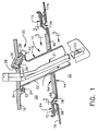
- the heat shield of the present invention is positioned in the augmentor 12 of a gas turbine engine of a type similar to that described in U.S. Patent No. 4,813,229, the disclosure of which is incorporated herein by reference.
- the heat shield includes a housing 14 which is attached to the outer duct wall 16 and extends through the diffuser wall 18.
- the outer duct wall 16 and diffuser wall 18 between them define a bypass duct 20 of conventional design for conveying cooling bypass air rearwardly from the core engine.
- the housing 14 has an oval, aerodynamic shape in cross-section (see Fig. 2), and is elongated in shape in elevation and encloses a substantially radially-inwardly extending fuel tube assembly 21 which also passes through the outer duct wall 16 and diffuser wall 18.
- the housing includes a forward-facing opening 22 which forms a scoop for conveying cooling air from the bypass duct 20 along the interior of the housing 14.
- the housing includes elongated, oval openings 23, positioned along the lateral sides of the housing in registry with the side orifices of the fuel tube assembly 21. The openings 23 also allow cooling air to exit the housing 14.
- the openings are oval so that relative thermal expansion of the housing 14 will not result in the orifice of the fuel tube assembly 21 being blocked.
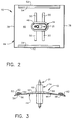
- the housing 14 is generally oval in cross-section and includes a forwardly extending nose 24 and an aft end forming a boss 26 having a bore 28 for receiving a threaded bolt 30, which may be a self-retaining bolt.
- the outer duct wall 16 includes a lip 32 forming a slot 34 shaped to receive the nose 24.
- the outer duct wall 16 includes a boss 36 forming a bore 38 shaped to receive a nut 40 in a press fit.
- the bores 28, 38 are aligned and angled relative to the outer duct wall 16 such that tightening the bolt 30 forces the nose 24 into the slot 34.
- the bolt 30 includes a cap 42 which is seated on the boss 26 and clamps the boss and housing against the outer duct wall 16 when tightened.
- the heat shield 10 includes a diffuser flowpath segment, generally designated 44.
- the diffuser flowpath segment 44 includes a substantially rectangular arcuate base plate 46 of sheet metal which is attached to the housing 14.
- the base plate 46 includes a raised collar 48 and a plurality of splayed ribs 50 extending outwardly from the collar.
- the ribs 50 act to stiffen the base plate 46 and change its vibration characteristics.
- the ribs 50 shown are sufficient to change the vibration characteristics of the base plate 46 such that the first natural frequency of the base plate is above the highest engine speed. In practice, this would require that the natural frequency of the base plate exceed about 166 hz, since engine speed typically reaches 10,000 rpm.
- the axially-extending longitudinal edges 52 of the base plate 46 include raised ribs 54 forming slots 56.
- the slots 56 receive longitudinally extending spline seals 58 such that adjacent base plates 60, 62 are joined to base plate 46 by spline seals 58.
- the joints thus formed provide an air seal.
- the diffuser flowpath segments 44 form a continuous ring and an extension of the diffuser wall 18.
- Spline seals 58 can be inserted laterally into slots 56 as the shields 10 are being installed for the first time.
- the spline 58 may be inserted into a slot through the aft leaf spring, as will be described below.
- the diffuser wall 18 includes a leaf seal 64 which forms a seal between the diffuser flowpath segment and a contiguous portion of the diffuser wall 18.
- Each leaf seal 64 includes a base member 66 welded or brazed to an outer surface of the diffuser wall 18 and having a generally U-shape.
- a plurality of leaf elements 68 are mounted on the base portion 66 by rivets 70.
- a second leaf spring assembly 72 is mounted on a continuation of 74 of the diffuser wall 18 and forms a seal between the rearward transverse edge 76 of the base plate 46.
- the rearward transverse edge 76 and forward transverse edge 78 are slightly upturned to avoid projecting into the augmentor volume 12 and creating undesirable turbulence in the augmentor.
- the housing 14' includes a flared, frustoconical upper end 80 which abuts the outer duct wall 16'.
- the front end of the upper end 80 is received within a wedge-shaped forward block 82 which is mounted on the wall 16' by a nut and bolt combination 84.
- the rear portion of the frustoconical upper end 80 is engaged by a wedge-shaped cam 86 mounted on the end of a mounting bolt 30' which is threaded through a boss 88 mounted on the wall 16'.
- the boss 88 includes an axially-extending guideway 90 which maintains proper orientation of the cam 86 relative to the upper end 80 and further, prevents deflection of the cam 86 away from the wall 16'.
- the housing 14' is mounted on the outer duct wall 16' by tightening the bolt 30' against the boss 88. This causes the cam 86 to jam against the aft portion of the frustoconical upper end 80 of the housing 14', which also urges the forward portion 80 against the block 82. Additional lateral support is effected by the inter-engagement of the diffuser flowpath segments 44 on the housings 14' of an array of heat shields 10'.
- the outer duct wall 16'' includes an opening 92 which receives a fuel tube header 94 which is integral with the fuel tube 21''.
- the forward end of the header 94 is attached to the duct wall 16'' by a nut and bolt combination 96, and the aft end includes a boss 98 which receives a nut 40 in a press fit.
- the bolt 30 is threaded into the nut 40 and carries a lug 100 having a forward lip 102 which engages in an aft extending flange 104 formed on the housing 14''.
- the outer duct wall 16'' includes a radially extending bead 106 which engages in undercut down the flange 104.
- the housing 14'' includes a forwardly projecting nose 108 which is received within a slot 110 formed by a lip 112 projecting radially inwardly from the header 94.
- the heat shield 14'' is attached to the header 94 by inserting the nose 108 within the slot 110, then threading the bolt 30 into the nut 40, which causes the lug 100 to clamp against the flanged 104.
- the bolt 30 also clamps the header 94 against the outer duct wall 16''.
- the outer duct 16''' includes a strut 114 having a body 116 which is attached to the duct 16''' by bolts 117 and includes, at its radially-inner end, a slot 118 at a forward end and a boss 120 at a rearward end which receives a nut 40.
- the strut 114 includes an opening 22''' for directing cooling air from bypass duct 20 radially inwardly through strut 114 and housing 14'''.
- the housing 14''' of the heat shield 10''' includes a forwardly projecting nose 24''', which engages the slot 118 at a forward end, and a flange 122 at an aft end which receives the bolt 30 therethrough.
- the end of the strut 114 is aligned with but not rigidly connected to the diffuser wall 18''', and includes an offset 124 which receives the bolt 30 so that the bolt does not project radially inwardly into the augmentor volume 12.
- a flange 126 is mounted on the outer surface of the diffuser wall 18''' and includes a rearwardly-opening slot 128.
- An oval seal ring 130 is inserted in the slot 128 and is captured by the strut. In assembly, the strut is inserted through the ring 130 and bolted to the outer duct wall 16''' by bolts 117.
- the heat shield has been attached to supporting structure in such a manner that it can be removed easily and quickly from within the augmentor volume.
- the attachment and removal procedure requires only the tightening down or backing off of a single mounting bolt for each shield.
- the bolt 30 may be accessed by a suitably long-shanked tool inserted through a hole (not shown) in the diffuser wall continuation 74, through the aft leaf spring 72 or through a VABI as described in copending application filed , Serial No. (attorney docket 13DV-10484), the disclosure of which is incorporated herein by reference.
- it is a simple matter for one to reach around the open longitudinal edge 52 to access bolt 30.
- attachment structure for the heat shield can be applied to other structures within the exhaust system without departing from the scope of the invention.
- the attachment mechanism can be employed to mount a flame holder of the type disclosed in the aforementioned Gastebois U.S. Patent No. 4,899,539, as well as Grant, Jr. U.S. Patent No. 4,989,407. The disclosures of which are incorporated herein by reference.
Applications Claiming Priority (2)
| Application Number | Priority Date | Filing Date | Title |
|---|---|---|---|
| US81600092A | 1992-01-02 | 1992-01-02 | |
| US816000 | 1992-01-02 |
Publications (1)
| Publication Number | Publication Date |
|---|---|
| EP0550126A1 true EP0550126A1 (de) | 1993-07-07 |
Family
ID=25219406
Family Applications (1)
| Application Number | Title | Priority Date | Filing Date |
|---|---|---|---|
| EP92307914A Withdrawn EP0550126A1 (de) | 1992-01-02 | 1992-09-01 | Hitzeschild für Nachbrenner |
Country Status (3)
| Country | Link |
|---|---|
| US (1) | US5335490A (de) |
| EP (1) | EP0550126A1 (de) |
| JP (1) | JPH05231176A (de) |
Cited By (8)
| Publication number | Priority date | Publication date | Assignee | Title |
|---|---|---|---|---|
| EP0713057A1 (de) * | 1994-11-16 | 1996-05-22 | ROLLS-ROYCE plc | Hochtemperatur Montage |
| WO1999054597A1 (de) * | 1998-04-21 | 1999-10-28 | Siemens Aktiengesellschaft | Turbinenschaufel |
| US6887040B2 (en) | 2001-09-12 | 2005-05-03 | Siemens Aktiengesellschaft | Turbine blade/vane |
| EP1840471A2 (de) | 2006-03-31 | 2007-10-03 | ALSTOM Technology Ltd | Vorrichtung zur Befestigung eines sequentiell betriebenen Brenners in einer Gasturbinenanordnung |
| EP1840364A1 (de) * | 2006-03-30 | 2007-10-03 | Snecma | Vorrichtung zur Montage einer Flusstrennwand in einer Nachbrennkammer eines Turbinentriebwerks |
| EP2058476A1 (de) | 2007-11-09 | 2009-05-13 | Snecma | Verbindung von radialen Streben mit einem kreisförmigen Gehäuse durch Ineinandergreifen der eingesetzten Teile |
| WO2009127203A1 (de) * | 2008-04-17 | 2009-10-22 | Mtu Aero Engines Gmbh | Strebe für ein turbinenzwischengehäuse, turbinenzwischengehäuse und verfahren zur herstellung eines turbinenzwischengehäuses |
| WO2014105573A1 (en) * | 2012-12-29 | 2014-07-03 | United Technologies Corporation | Heat shield based air dam for a turbine exhaust case |
Families Citing this family (45)
| Publication number | Priority date | Publication date | Assignee | Title |
|---|---|---|---|---|
| FR2708086B1 (fr) * | 1993-06-30 | 1995-09-01 | Snecma | Structure tubulaire sectorisée travaillant à l'implosion. |
| US5396763A (en) * | 1994-04-25 | 1995-03-14 | General Electric Company | Cooled spraybar and flameholder assembly including a perforated hollow inner air baffle for impingement cooling an outer heat shield |
| US5560198A (en) * | 1995-05-25 | 1996-10-01 | United Technologies Corporation | Cooled gas turbine engine augmentor fingerseal assembly |
| US6141968A (en) * | 1997-10-29 | 2000-11-07 | Pratt & Whitney Canada Corp. | Fuel nozzle for gas turbine engine with slotted fuel conduits and cover |
| US6125627A (en) | 1998-08-11 | 2000-10-03 | Allison Advanced Development Company | Method and apparatus for spraying fuel within a gas turbine engine |
| US6553769B2 (en) * | 1998-12-16 | 2003-04-29 | General Electric Company | Method for providing concentricity of pilot fuel assembly in a combustor |
| US6295801B1 (en) * | 1998-12-18 | 2001-10-02 | General Electric Company | Fuel injector bar for gas turbine engine combustor having trapped vortex cavity |
| US6286298B1 (en) * | 1998-12-18 | 2001-09-11 | General Electric Company | Apparatus and method for rich-quench-lean (RQL) concept in a gas turbine engine combustor having trapped vortex cavity |
| US6438940B1 (en) * | 1999-12-21 | 2002-08-27 | General Electric Company | Methods and apparatus for providing uniform ignition in an augmenter |
| US6540162B1 (en) * | 2000-06-28 | 2003-04-01 | General Electric Company | Methods and apparatus for decreasing combustor emissions with spray bar assembly |
| US6463739B1 (en) | 2001-02-05 | 2002-10-15 | General Electric Company | Afterburner heat shield |
| US6415609B1 (en) * | 2001-03-15 | 2002-07-09 | General Electric Company | Replaceable afterburner heat shield |
| TW591372B (en) * | 2003-05-15 | 2004-06-11 | High Tech Comp Corp | Power control method of portable electronic device, portable electronic device and electronic system |
| US7415828B2 (en) * | 2003-05-29 | 2008-08-26 | Pratt & Whitney Canada Corp. | Fuel nozzle sheath retention ring |
| FR2869954B1 (fr) * | 2004-05-05 | 2006-06-16 | Snecma Moteurs Sa | Dispositif de fixation d'un anneau bruleur dans une chambre de postcombustion d'un turboreacteur |
| US6983601B2 (en) * | 2004-05-28 | 2006-01-10 | General Electric Company | Method and apparatus for gas turbine engines |
| US7229249B2 (en) * | 2004-08-27 | 2007-06-12 | Pratt & Whitney Canada Corp. | Lightweight annular interturbine duct |
| FR2875855B1 (fr) * | 2004-09-27 | 2006-12-22 | Snecma Moteurs Sa | Turboreacteur avec un bras monobloc de raccord de servitudes et le bras monobloc de raccord de servitudes |
| US7464536B2 (en) * | 2005-07-07 | 2008-12-16 | General Electric Company | Methods and apparatus for assembling gas turbine engines |
| US7596950B2 (en) * | 2005-09-16 | 2009-10-06 | General Electric Company | Augmentor radial fuel spray bar with counterswirling heat shield |
| US20070193272A1 (en) * | 2006-02-21 | 2007-08-23 | Woodward Fst, Inc. | Gas turbine engine fuel injector |
| US7909570B2 (en) * | 2006-08-25 | 2011-03-22 | Pratt & Whitney Canada Corp. | Interturbine duct with integrated baffle and seal |
| CA2672120A1 (en) | 2006-12-07 | 2008-06-12 | Novartis Ag | Antagonistic antibodies against ephb3 |
| US8196410B2 (en) * | 2007-05-18 | 2012-06-12 | Pratt & Whitney Canada Corp. | Stress reduction feature to improve fuel nozzle sheath durability |
| DE102008028025B4 (de) * | 2008-06-12 | 2011-05-05 | Siemens Aktiengesellschaft | Hitzeschildanordnung |
| US8069648B2 (en) * | 2008-07-03 | 2011-12-06 | United Technologies Corporation | Impingement cooling for turbofan exhaust assembly |
| US20100162714A1 (en) * | 2008-12-31 | 2010-07-01 | Edward Claude Rice | Fuel nozzle with swirler vanes |
| US8393154B2 (en) * | 2009-02-12 | 2013-03-12 | Pratt & Whitney Canada Corp. | Fuel delivery system with reduced heat transfer to fuel manifold seal |
| US8596959B2 (en) * | 2009-10-09 | 2013-12-03 | Pratt & Whitney Canada Corp. | Oil tube with integrated heat shield |
| US8844643B2 (en) | 2011-03-08 | 2014-09-30 | Honeywell International Inc. | Fireproof systems with local heat shields for aircraft engines |
| US20130199191A1 (en) * | 2011-06-10 | 2013-08-08 | Matthew D. Tyler | Fuel injector with increased feed area |
| US9638422B2 (en) * | 2012-06-22 | 2017-05-02 | Delavan Inc. | Active purge mechanism with backflow preventer for gas turbine fuel injectors |
| US9470151B2 (en) | 2012-12-21 | 2016-10-18 | United Technologies Corporation | Alignment system and methodology to account for variation in a gas turbine engine |
| US9863261B2 (en) | 2012-12-29 | 2018-01-09 | United Technologies Corporation | Component retention with probe |
| FR3012514B1 (fr) * | 2013-10-31 | 2015-12-25 | Airbus Operations Sas | Dispositif de protection thermique d'un equipement dans un compartiment moteur de turbomachine |
| US9879606B2 (en) | 2014-07-28 | 2018-01-30 | Pratt & Whitney Canada Corp. | Method of supplying fuel to an internal fuel manifold |
| US9869204B2 (en) * | 2015-03-06 | 2018-01-16 | United Technologies Corporation | Integrated inner case heat shield |
| CN105841193B (zh) * | 2016-05-18 | 2018-07-20 | 葛明龙 | 两种航空航天涡扇发动机 |
| US11230995B2 (en) * | 2017-11-08 | 2022-01-25 | Raytheon Technologies Corporation | Cable conduit for turbine engine bypass |
| EP3797211B1 (de) * | 2018-06-07 | 2023-10-18 | Siemens Energy Global GmbH & Co. KG | Verminderung von rissbildung im turbinen-abgastrakt unter verwendung von teilmanschetten |
| US11725529B2 (en) * | 2019-02-08 | 2023-08-15 | Raytheon Technologies Corporation | Fluid transfer assembly for rotational equipment |
| JP7419002B2 (ja) * | 2019-09-12 | 2024-01-22 | 三菱重工業株式会社 | ストラットカバー、排気車室およびガスタービン |
| GB202006964D0 (en) * | 2020-05-12 | 2020-06-24 | Rolls Royce Plc | Afterburner strut with integrated fueld feed lines |
| US11702946B1 (en) * | 2022-07-13 | 2023-07-18 | Pratt & Whitney Canada Corp. | Service tube locking device |
| CN115992776B (zh) * | 2023-03-23 | 2023-06-02 | 中国航发沈阳发动机研究所 | 一种发动机涡轮后推力增加部件 |
Citations (10)
| Publication number | Priority date | Publication date | Assignee | Title |
|---|---|---|---|---|
| US2766963A (en) * | 1952-11-01 | 1956-10-16 | Gen Motors Corp | Turbine stator assembly |
| US2861424A (en) * | 1954-04-09 | 1958-11-25 | Douglas Aircraft Co Inc | Fuel supply means for combustion apparatus |
| FR2330867A1 (fr) * | 1975-11-04 | 1977-06-03 | Gen Electric | Stabilisateur de flamme amovible |
| FR2482661A1 (fr) * | 1980-05-16 | 1981-11-20 | United Technologies Corp | Assemblage directeur d'ecoulement pour une turbine a gaz |
| EP0328813A1 (de) * | 1988-02-18 | 1989-08-23 | General Electric Company | Flammenhalter für ein Gasturbinentriebwerk |
| FR2636378A1 (fr) * | 1988-09-14 | 1990-03-16 | Snecma | Redresseur de soufflante de turboreacteur a double flux |
| GB2226086A (en) * | 1988-12-14 | 1990-06-20 | Gen Electric | Gas turbine engine frame |
| EP0387123A1 (de) * | 1989-03-08 | 1990-09-12 | Societe Nationale D'etude Et De Construction De Moteurs D'aviation "Snecma" | Thermische Schutzauskleidung für das heisse Rohr eines Turboluftstrahltriebwerkes |
| DE4033678A1 (de) * | 1989-10-24 | 1991-04-25 | United Technologies Corp | Ummantelungshalter fuer laufschaufeln von gasturbinen |
| FR2660362A1 (fr) * | 1990-04-03 | 1991-10-04 | Gen Electric | Structure de fixation des extremites exterieures des aubes d'une turbine. |
Family Cites Families (15)
| Publication number | Priority date | Publication date | Assignee | Title |
|---|---|---|---|---|
| US3646763A (en) * | 1970-05-25 | 1972-03-07 | Gen Electric | Gas turbine engine with improved afterburner |
| US3780529A (en) * | 1971-08-05 | 1973-12-25 | Gen Motors Corp | Combustion apparatus |
| BE795529A (fr) * | 1972-02-17 | 1973-06-18 | Gen Electric | Allumeur monte sur un dispositif d'augmentation de la poussee de turboreacteurs et refroidi a l'air |
| US3879940A (en) * | 1973-07-30 | 1975-04-29 | Gen Electric | Gas turbine engine fuel delivery tube assembly |
| US4312185A (en) * | 1980-02-19 | 1982-01-26 | General Electric Company | Low profile fuel injection system |
| US4426191A (en) * | 1980-05-16 | 1984-01-17 | United Technologies Corporation | Flow directing assembly for a gas turbine engine |
| US4431373A (en) * | 1980-05-16 | 1984-02-14 | United Technologies Corporation | Flow directing assembly for a gas turbine engine |
| FR2588920B1 (fr) * | 1985-10-23 | 1987-12-04 | Snecma | Turboreacteur a postcombustion a injecteurs de postcombustion radiaux individuels |
| US4751815A (en) * | 1986-08-29 | 1988-06-21 | United Technologies Corporation | Liquid fuel spraybar |
| US4989407A (en) * | 1986-08-29 | 1991-02-05 | United Technologies Corporation | Thrust augmentor flameholder |
| US4706453A (en) * | 1986-11-12 | 1987-11-17 | General Motors Corporation | Support and seal assembly |
| FR2626044A1 (fr) * | 1988-01-14 | 1989-07-21 | Snecma | Melangeur de flux a section variable avec stabilisateur de rechauffe integre pour turboreacteur double flux |
| US5022805A (en) * | 1989-02-16 | 1991-06-11 | Rolls-Royce Incorporated | Cantilever mounting system for structural members having dissimilar coefficients of thermal expansion |
| FR2646880A1 (fr) * | 1989-05-11 | 1990-11-16 | Snecma | Chemise de protection thermique pour canal de post-combustion ou de transition d'un turboreacteur |
| US5031407A (en) * | 1989-06-06 | 1991-07-16 | Allied-Signal Inc. | Apparatus for use in a fuel delivery system for a gas turbine engine |
-
1992
- 1992-09-01 EP EP92307914A patent/EP0550126A1/de not_active Withdrawn
- 1992-09-02 JP JP4234626A patent/JPH05231176A/ja active Pending
-
1993
- 1993-06-30 US US08/084,886 patent/US5335490A/en not_active Expired - Lifetime
Patent Citations (10)
| Publication number | Priority date | Publication date | Assignee | Title |
|---|---|---|---|---|
| US2766963A (en) * | 1952-11-01 | 1956-10-16 | Gen Motors Corp | Turbine stator assembly |
| US2861424A (en) * | 1954-04-09 | 1958-11-25 | Douglas Aircraft Co Inc | Fuel supply means for combustion apparatus |
| FR2330867A1 (fr) * | 1975-11-04 | 1977-06-03 | Gen Electric | Stabilisateur de flamme amovible |
| FR2482661A1 (fr) * | 1980-05-16 | 1981-11-20 | United Technologies Corp | Assemblage directeur d'ecoulement pour une turbine a gaz |
| EP0328813A1 (de) * | 1988-02-18 | 1989-08-23 | General Electric Company | Flammenhalter für ein Gasturbinentriebwerk |
| FR2636378A1 (fr) * | 1988-09-14 | 1990-03-16 | Snecma | Redresseur de soufflante de turboreacteur a double flux |
| GB2226086A (en) * | 1988-12-14 | 1990-06-20 | Gen Electric | Gas turbine engine frame |
| EP0387123A1 (de) * | 1989-03-08 | 1990-09-12 | Societe Nationale D'etude Et De Construction De Moteurs D'aviation "Snecma" | Thermische Schutzauskleidung für das heisse Rohr eines Turboluftstrahltriebwerkes |
| DE4033678A1 (de) * | 1989-10-24 | 1991-04-25 | United Technologies Corp | Ummantelungshalter fuer laufschaufeln von gasturbinen |
| FR2660362A1 (fr) * | 1990-04-03 | 1991-10-04 | Gen Electric | Structure de fixation des extremites exterieures des aubes d'une turbine. |
Cited By (20)
| Publication number | Priority date | Publication date | Assignee | Title |
|---|---|---|---|---|
| EP0713057A1 (de) * | 1994-11-16 | 1996-05-22 | ROLLS-ROYCE plc | Hochtemperatur Montage |
| WO1999054597A1 (de) * | 1998-04-21 | 1999-10-28 | Siemens Aktiengesellschaft | Turbinenschaufel |
| US6533544B1 (en) | 1998-04-21 | 2003-03-18 | Siemens Aktiengesellschaft | Turbine blade |
| US6887040B2 (en) | 2001-09-12 | 2005-05-03 | Siemens Aktiengesellschaft | Turbine blade/vane |
| US7908868B2 (en) | 2006-03-30 | 2011-03-22 | Snecma | Device for mounting an air-flow dividing wall in a turbojet engine afterburner |
| EP1840364A1 (de) * | 2006-03-30 | 2007-10-03 | Snecma | Vorrichtung zur Montage einer Flusstrennwand in einer Nachbrennkammer eines Turbinentriebwerks |
| FR2899280A1 (fr) * | 2006-03-30 | 2007-10-05 | Snecma Sa | Dispositif de montage d'une paroi de separation de flux dans une chambre de post-combustion d'un turboreacteur |
| EP2077421A2 (de) | 2006-03-31 | 2009-07-08 | ALSTOM Technology Ltd | Vorrichtung zur Befestigung eines sequentiell betriebenen Brenners in einer Gasturbinenanordnung |
| EP1840471A3 (de) * | 2006-03-31 | 2008-02-20 | ALSTOM Technology Ltd | Vorrichtung zur Befestigung eines sequentiell betriebenen Brenners in einer Gasturbinenanordnung |
| EP2077421A3 (de) * | 2006-03-31 | 2009-07-15 | ALSTOM Technology Ltd | Vorrichtung zur Befestigung eines sequentiell betriebenen Brenners in einer Gasturbinenanordnung |
| EP1840471A2 (de) | 2006-03-31 | 2007-10-03 | ALSTOM Technology Ltd | Vorrichtung zur Befestigung eines sequentiell betriebenen Brenners in einer Gasturbinenanordnung |
| US7937950B2 (en) | 2006-03-31 | 2011-05-10 | Alstom Technology Ltd. | Device for fastening a sequentially operated burner in a gas turbine arrangement |
| EP2058476A1 (de) | 2007-11-09 | 2009-05-13 | Snecma | Verbindung von radialen Streben mit einem kreisförmigen Gehäuse durch Ineinandergreifen der eingesetzten Teile |
| FR2923529A1 (fr) * | 2007-11-09 | 2009-05-15 | Snecma Sa | Raccordement de bras radiaux a une virole circulaire par imbrication de pieces rapportees |
| US8303246B2 (en) | 2007-11-09 | 2012-11-06 | Snecma | Connecting radial arms to a circular ferrule by imbricating attached parts |
| RU2492331C2 (ru) * | 2007-11-09 | 2013-09-10 | Снекма | Устройство для соединения радиальных кронштейнов с круглым кольцом и турбомашина |
| WO2009127203A1 (de) * | 2008-04-17 | 2009-10-22 | Mtu Aero Engines Gmbh | Strebe für ein turbinenzwischengehäuse, turbinenzwischengehäuse und verfahren zur herstellung eines turbinenzwischengehäuses |
| US8579583B2 (en) | 2008-04-17 | 2013-11-12 | MTU Aero Engines AG | Strut for an intermediate turbine housing, intermediate turbine housing, and method for producing an intermediate turbine housing |
| WO2014105573A1 (en) * | 2012-12-29 | 2014-07-03 | United Technologies Corporation | Heat shield based air dam for a turbine exhaust case |
| US9976442B2 (en) | 2012-12-29 | 2018-05-22 | United Technologies Corporation | Heat shield based air dam for a turbine exhaust case |
Also Published As
| Publication number | Publication date |
|---|---|
| US5335490A (en) | 1994-08-09 |
| JPH05231176A (ja) | 1993-09-07 |
Similar Documents
| Publication | Publication Date | Title |
|---|---|---|
| EP0550126A1 (de) | Hitzeschild für Nachbrenner | |
| JP4053303B2 (ja) | アフタバーナ熱シールド及びそれを支持するための支柱 | |
| EP2312217B1 (de) | Brennkammer für eine Gasturbine | |
| US6449952B1 (en) | Removable cowl for gas turbine combustor | |
| US7827800B2 (en) | Combustor heat shield | |
| US5524430A (en) | Gas-turbine engine with detachable combustion chamber | |
| EP0797747B1 (de) | Strömungsleitplatte zur kühlung der stirnwand einer turbinenbrennkammer | |
| US5142871A (en) | Combustor dome plate support having uniform thickness arcuate apex with circumferentially spaced coolant apertures | |
| US4380906A (en) | Combustion liner cooling scheme | |
| EP1640565B1 (de) | Durch aerodynamische Wirbel verbesserter Schutzschild für Befestigungselemente einer Turbomaschine | |
| EP0521687A1 (de) | Aufbau eines Brennkammerdomes | |
| EP0797748B1 (de) | Halterung für kraftstoffeinspritzdüsen | |
| JPH01210721A (ja) | 低乱流フレームホルダ取付装置 | |
| JPH04227413A (ja) | ガスタービンエンジン燃焼器用のドームアセンブリ | |
| JP3998494B2 (ja) | 交換可能なアフタバーナ熱シールド | |
| US4487015A (en) | Mounting arrangements for combustion equipment | |
| US4259839A (en) | Flame holder devices for combustion chambers of turbojet engine afterburner tubes | |
| AU674727B2 (en) | Removable afterburner flameholder | |
| EP3760927A1 (de) | Befestigungsanordnung für eine schwimmende manschette einer brennkammer | |
| JPH0674756B2 (ja) | シ−ル装置 |
Legal Events
| Date | Code | Title | Description |
|---|---|---|---|
| PUAI | Public reference made under article 153(3) epc to a published international application that has entered the european phase |
Free format text: ORIGINAL CODE: 0009012 |
|
| AK | Designated contracting states |
Kind code of ref document: A1 Designated state(s): DE FR GB |
|
| STAA | Information on the status of an ep patent application or granted ep patent |
Free format text: STATUS: THE APPLICATION IS DEEMED TO BE WITHDRAWN |
|
| 18D | Application deemed to be withdrawn |
Effective date: 19940108 |