EP1640565B1 - Durch aerodynamische Wirbel verbesserter Schutzschild für Befestigungselemente einer Turbomaschine - Google Patents
Durch aerodynamische Wirbel verbesserter Schutzschild für Befestigungselemente einer Turbomaschine Download PDFInfo
- Publication number
- EP1640565B1 EP1640565B1 EP05255501A EP05255501A EP1640565B1 EP 1640565 B1 EP1640565 B1 EP 1640565B1 EP 05255501 A EP05255501 A EP 05255501A EP 05255501 A EP05255501 A EP 05255501A EP 1640565 B1 EP1640565 B1 EP 1640565B1
- Authority
- EP
- European Patent Office
- Prior art keywords
- fastener
- fastener shield
- shield
- fluid flow
- bolts
- Prior art date
- Legal status (The legal status is an assumption and is not a legal conclusion. Google has not performed a legal analysis and makes no representation as to the accuracy of the status listed.)
- Expired - Fee Related
Links
Images


Classifications
-
- F—MECHANICAL ENGINEERING; LIGHTING; HEATING; WEAPONS; BLASTING
- F01—MACHINES OR ENGINES IN GENERAL; ENGINE PLANTS IN GENERAL; STEAM ENGINES
- F01D—NON-POSITIVE DISPLACEMENT MACHINES OR ENGINES, e.g. STEAM TURBINES
- F01D25/00—Component parts, details, or accessories, not provided for in, or of interest apart from, other groups
- F01D25/24—Casings; Casing parts, e.g. diaphragms, casing fastenings
- F01D25/243—Flange connections; Bolting arrangements
-
- F—MECHANICAL ENGINEERING; LIGHTING; HEATING; WEAPONS; BLASTING
- F01—MACHINES OR ENGINES IN GENERAL; ENGINE PLANTS IN GENERAL; STEAM ENGINES
- F01D—NON-POSITIVE DISPLACEMENT MACHINES OR ENGINES, e.g. STEAM TURBINES
- F01D11/00—Preventing or minimising internal leakage of working-fluid, e.g. between stages
- F01D11/001—Preventing or minimising internal leakage of working-fluid, e.g. between stages for sealing space between stator blade and rotor
-
- F—MECHANICAL ENGINEERING; LIGHTING; HEATING; WEAPONS; BLASTING
- F05—INDEXING SCHEMES RELATING TO ENGINES OR PUMPS IN VARIOUS SUBCLASSES OF CLASSES F01-F04
- F05B—INDEXING SCHEME RELATING TO WIND, SPRING, WEIGHT, INERTIA OR LIKE MOTORS, TO MACHINES OR ENGINES FOR LIQUIDS COVERED BY SUBCLASSES F03B, F03D AND F03G
- F05B2260/00—Function
- F05B2260/30—Retaining components in desired mutual position
- F05B2260/301—Retaining bolts or nuts
-
- F—MECHANICAL ENGINEERING; LIGHTING; HEATING; WEAPONS; BLASTING
- F05—INDEXING SCHEMES RELATING TO ENGINES OR PUMPS IN VARIOUS SUBCLASSES OF CLASSES F01-F04
- F05D—INDEXING SCHEME FOR ASPECTS RELATING TO NON-POSITIVE-DISPLACEMENT MACHINES OR ENGINES, GAS-TURBINES OR JET-PROPULSION PLANTS
- F05D2260/00—Function
- F05D2260/97—Reducing windage losses
Definitions
- This invention relates generally to turbomachines such as gas turbine engines and, more particularly, to an improved fastener shield for minimizing temperature rise associated with protrusions in a fluid flow path.
- cooling air is extracted from a compressor section of the engine and routed through various channels to the turbine section. As the cooling air is subjected to work input in passing through these channels, the temperature of the cooling air rises.
- Elements that have been found to significantly affect work in the cooling fluid flow are nuts and bolt heads utilized in connecting various sections of the turbine together. These fastener elements protrude into the cooling air channels creating aerodynamic drag, causing heating of the cooling fluid in a manner that the cooling air receives more work.
- the U.S. Patents referenced above describe fastener shields that improve the performance of gas turbine engines.
- the fastener shields described therein are particularly useful with flange connections that protrude into the fluid flow passage and are connected together by bolts with heads in the fluid flow passage.
- the fastener shield described in the '397 Patent includes a continuous ring having a generally L-shaped profile that is captured between the bolt head and an upstream flange.
- the captured flange portion of the shield is provided with a plurality of circumferentially spaced, milled slots contoured to receive D-shaped bolt heads. These bolt heads are mounted flush with the upstream captured portion of the shield, thus eliminating open access holes and protruding bolts.
- the combination of D-shaped heads and contoured slots provides a means for torquing the bolts.
- the cylindrical section of the L-shaped shield extends downstream of the mating flanges and passes the nut side of the bolted connection to direct cooling air past the nut, thereby minimizing velocity reduction from the nut, and represented a distinct improvement over prior art flange connections, such as shown in Figure 3 of the '397 Patent.
- the fastener shield as described in the '397 Patent is effective to reduce drag effects within the fluid flow channel of a gas turbine engine
- a plurality of contoured slots must be machined in the surface of the fastener shield facing the fluid flow path so that the heads of the bolts fit into the precision machined slots of the shield.
- the described fastener shield has an L-shaped cross-section with a portion which extends parallel to the direction of fluid flow within the fluid flow channel with the described intent of directing the main fluid flow past bolt heads on the opposite side of the bolted flange.
- the '865 Patent thus provides a continuous ring of substantially rectangular cross-section formed with a plurality of circumferentially spaced, arcuate-shaped grooves on a first surface of the ring that are oriented so that the ring may be positioned over the bolt heads within the grooves of the ring.
- a plurality of apertures formed through the ring are aligned with the apertures in the spaces between adjacent grooves.
- Each of the apertures has a countersunk portion on an outward side of the ring opposite the side containing the grooves.
- At least some of the bolts connecting the flanges together extend through the ring at the apertures for holding the ring in position over the bolt heads.
- the bolts extending through the ring have heads that are recessed into the countersunk areas, with the top of the bolt heads lying flush with the outer surface of the ring.
- the countersunk portions fit snugly around the bolt heads to minimize the area of any cavity which could be exposed and lead to disturbance in the fluid flow path.
- the ring is designed so that when placed in its operative position over the bolt heads, the lower surface of the ring in which the grooves are formed fits snugly against the flange and one edge of the ring also abuts the annular member to which the flange is attached. Fluid is thus prevented from passing under the fastener shield.
- the present invention provides further advantages over the above-described fastener shields by further reducing the temperature through the high pressure turbine forward shaft area.
- the present invention provides an improved fastener shield for use in gas turbine engines to minimize temperature rise in cooling fluid flow due to protrusions and, more particularly, to nut and bolt protrusions associated with the flange connections in the coolant flow path.
- the fastener shield according to the present invention provides an aerodynamic effect to the CDP seal while avoiding attachment of the nuts directly to the CDP seal. This in turn avoids the necessity of having to completely disassemble the engine when a bolt and nut have seized.
- the above-recited aspects and advantages are attained in an improved fastener shield for use with bolt head flange connections having bolt heads and nuts which protrude into a fluid flow channel.
- the shield of the present invention comprises a fastener shield for use in a fluid flow path within a gas turbine engine for reducing fluid drag and heating generated by fluid flow over a plurality of circumferentially spaced fasteners, the fasteners having a portion thereof extending into the fluid flow path.
- the fastener shield includes a radially-extending, downstream-facing mounting flange having a plurality of circumferentially spaced bolt holes positioned to receive respective engine mounting bolts therethrough, and to attach the mounting flange to elements of the turbine engine.
- a curved, upstream-facing fastener shield cover is positioned in spaced-apart relation to the mounting flange for at least partially covering and separating an exposed, upstream-facing portion of the bolts from the fluid flow to thereby reduce drag and consequent heating of the bolts.
- a plurality of closely spaced-apart, spirally-oriented channels defined in the fastener shield cover are provided for deflecting the fluid flow impinging on the fastener shield cover, thereby increasing the tangential velocity and lowering the relative temperature of the fluid flow.
- the mounting flange and fastener shield cover are integrally-formed.
- the channel extends forward to aft at an acute angle of 30 degrees relative to a line tangent to the peripheral surface of the shield cover and is consistent with the rotation of the high-pressure turbine shaft.
- the fastener shield comprises a single, integrally-formed annular element.
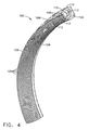
- the curved shield cover has a bellmouth shape characterized by a progressive curve that simultaneously extends axially upstream against the direction of fluid flow and radially outwardly to a terminus.
- the terminus is positioned in a plane defined by an extended longitudinal axis of the bolt.
- a gas turbine engine incorporating a fastener shield according to the present invention is illustrated in Figure 3 and shown generally at reference numeral 10.
- the engine 10 includes an annular outer casing 12 that encloses the operating components of the engine 10.
- Engine 10 has a longitudinal axis 11, about which the several rotating components of the engine 10 rotate.
- An air inlet 14 is provided into which air is drawn.
- the air enters a fan section 16 containing a fan 17 within which the pressure and the velocity of the inlet air are increased.
- Fan section 16 includes a multiple-stage fan 17 that is enclosed by a fan casing 18.
- Fan outlet air exits from the multiple-stage fan 17 and passes an annular divider 20 that divides the fan outlet air stream into a bypass airflow stream 19 and a core engine airflow stream 21.
- the bypass airflow stream 19 flows into and through an annular bypass duct 22 that surrounds and that is spaced outwardly from the core engine 24.
- the core engine airflow stream 21 flows into an annular inlet 26 of core engine 24.
- Core engine 24 includes an axial-flow compressor 28 that is positioned downstream of inlet 26 and serves to further increase the pressure of the air that enters inlet 26.
- High-pressure air exits compressor 28 and enters an annular combustion chamber 30 into which fuel is injected from a source of fuel (not shown) through a plurality of respective circumferentially-spaced fuel nozzles 32.
- the fuel-air mixture is ignited to increase the temperature of, and thereby to add energy to, the pressurized air that exits from compressor 28.
- the resulting high temperature combustion products pass from combustion chamber 30 to drive a first, high-pressure turbine 34 that is connected to and thus rotates compressor 28.
- combustion products After exiting high-pressure turbine 34 the combustion products then pass to and enter a second, low-pressure turbine 36 that is connected to and thus rotates the multiple-stage fan 17.
- the combustion products that exit from low-pressure turbine 36 then flow into and through an augmenter 40 that is enclosed by a tubular casing 41, to mix with bypass airflow that enters augmenter 40 from bypass duct 22.
- additional fuel is introduced into the core engine 24 at a point downstream of low-pressure turbine 36.
- Fuel is also introduced into the bypass air stream at substantially the same position along engine longitudinal axis 11.
- flameholders 38 and 42 are provided in the core engine air flow stream 21 and in the bypass flow stream, respectively, to stabilize the flame fronts in the bypass flow stream 19 and the core engine flow stream 21, respectively.
- the fastener shield 100 includes an annular ring 102 having a cross-section that includes a downstream-facing, radially-extending mounting flange 104 having a plurality of bolt holes 106 for receiving bolts 107, and an upstream-facing, radially-extending arcuate fastener shield cover 108.
- the fastener shield 100 may be formed of segments or fabricated in a single annular configuration, not shown. The segmented configuration offers the advantage that repairs involving only a portion of the circumference of the engine 10 can be accomplished by removing only the segment or segments necessary to accomplish the repair.
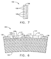
- the upstream-facing fastener shield cover 108 includes a regular array of angled, spaced-apart channels 109, as also shown in Figure 7 and described in further detail below. These channels 109 deflect gases impinging on the fastener shield cover 108, causing a swirling action as the gases flow downstream.
- the shield 100 includes mounting slots 110 formed on the flange 104 around the bolt holes 106.
- Nuts 113 are attached to the nut shield 108 using a swaging collar integral to the nut 113 which is swaged into a countersink in the bolt hole in nut shield 108.
- the shape of the curved fastener shield cover 108 can be characterized as a "bellmouth" shape, and presents a progressive curve that simultaneously extends axially upstream against the direction of fluid flow and radially outwardly to a terminus.
- the geometry of the channels 109 is explained with reference to Figures 5 and 8 .
- the channels 109 extend at an acute angle of 30 degrees relative to a line tangent to the peripheral surface of the shield cover 108 and extend forward to aft in a direction consistent with the rotation of the HPT shaft 150.
- the forward end of the shield cover 108 has an outside diameter of 37 cm (14.64 in), an inside diameter of 34 cm (13.354 in) and an axial depth of 2.7 cm (1.06 in).
- Each channel 109 is 0.15 cm (0.06 in) wide, 0.15 cm (0.06 in) deep, and are spaced apart 1 degree.
- the wall thickness between channels 109 is 0.15 cm (0.06 in). Being an illustrative embodiment, these dimensions vary based on the geometry and size of the engine 10.
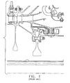
- the shield 100 acts in combination with a wall 120 extending in the downstream direction and formed integrally with the stage of outlet guide vanes 122.
- Diffuser inner frames 126 support the outlet guide vanes 122, as shown, in the proper relationship between upstream compressor 28 and downstream combustion chamber 30.
- the turbine portion 34 of the gas turbine engine 10 is typically cooled by air pressurized by the compressor 28. This coolant air is bled from the engine airflow stream 21 through CDP blocker holes, not shown, in the diffuser inner frame 126.
- the coolant flow rate is metered by the compressor discharge pressure (CDP) seal 134, which comprises a rotating seal portion 136 and a stationary seal portion 138.
- the CDP stationary seal portion 138 comprises a rigid CDP seal support 140 upon which a honeycomb seal 142 is bonded.
- the CDP stationary seal portion 138 is supported by radially extending diffuser frame flanges 126A and 139.
- the CDP rotating seal portion 136 is captured between rotor member 130 and labyrinth seal teeth 154 of the high pressure turbine shaft 150 which are closely spaced from the honeycomb seal 142.
- seal 134 is designed to operate with minimal running clearances between the labyrinth seal teeth 154 and stationary honeycomb seal 142.
- the fastener shield 100 is positioned with the curved fastener shield cover 108 facing upstream over the bolts 107 that extend in closely spaced-apart relation through the bolt holes 106 and through the aligned and mated flanges 126A and 139.
- the bolts 107 project forward with the head 107A of each bolt 107 positioned in the downstream direction and the shank of the bolt 107 with a nut 113 threaded and properly torqued thereon, facing upstream.
- the fastener shield cover 108 thus provides a smooth, progressive curve against which gas fluid flow obliquely impinges as it moves downstream in the engine 10.
- the channels 109 comprise an aerodynamic device that guides the CDP seal leakage flow traveling through the angled channels 109.
- the flow maintains its tangential momentum, leading to an increase in the swirl, i.e. tangential velocity of the cavity flow and thus decreases the relative air temperature. Since the majority of the CDP flow passes through the channels 109, the impingement location on the high-pressure turbine 150 shifts aft.
- the high-pressure turbine shaft 150 sees a lower relative temperature and a lower heat transfer cooefficient in the engine cavity aft of the CDP seal 134, resulting in a lower skin temperature on the high-pressure turbine shaft 150.
- fastener shield 100 is a separate element from the CDP stationary seal portion 138 and the nut shield "A" covering the head 107A of bolt 107.
- a swirl-enhanced aerodynamic fastener shield is described above.
Claims (6)
- Befestigungsschild (100) zur Verwendung in einem Fluidströmungspfad innerhalb eines Gasturbinentriebwerks zum Verringern des Fluidströmungswiderstands und der durch den Fluidstrom über mehrere in Umfangsrichtung in Abstand angeordnete Schrauben (107) erzeugten Erwärmung, wobei die Schrauben (107) einen sich in dem Fluidströmungspfad erstreckenden Abschnitt haben, und wobei der Befestigungsschild (100) aufweist:(a) einen sich radial erstreckenden, in Stromabwärtsrichtung zeigenden Befestigungsflansch (104) mit mehreren in Umfangsrichtung in Abstand angeordneten Schraubenlöchern, die dergestalt positioniert sind, dass die Löcher im Einsatz entsprechende Triebwerksbefestigungsschrauben (107) dadurch hindurch aufnehmen, um den Befestigungsflansch (104) an einem Element des Turbinentriebwerks zu befestigen; und(b) eine gekrümmte, in Stromaufwärtsrichtung zeigende Befestigungsschildabdeckung (108), die in Abstand zu dem Befestigungsflansch (104) positioniert ist, welche, wenn sie im Einsatz ist, wenigstens teilweise einen freiliegenden, stromaufwärts zeigenden Abschnitt der Schrauben (107) von der Fluidströmung abschirmt und trennt, um dadurch den Strömungswiderstand und die sich daraus ergebende Erwärmung der Schrauben (107) zu reduzieren; dadurch gekennzeichnet, dass(c) mehrere eng in Abstand angeordnete, spiralförmig ausgerichtete Kanäle (109) in der Befestigungsschildabdeckung (108) definiert sind, um die auf die Befestigungsschildabdeckung (108) auftreffende Verdichterauslassdruckströmung abzulenken, um dadurch die tangentiale Geschwindigkeit zu erhöhen und die relative Temperatur der Fluidströmung zu verringern.
- Befestigungsschild (100) nach Anspruch 1, wobei der Befestigungsflansch (104) und die Befestigungsschildabdeckung (108) in einem Stück ausgebildet sind.
- Befestigungsschild (100) nach Anspruch 1, wobei sich der Kanal (109) von vorne nach hinten in einem spitzen Winkel von 30 Grad in Bezug auf eine zu einer Umfangsoberfläche der Schildabdeckung (108) tangential verlaufenden Linie und im Einsatz in der Drehrichtung einer Hochdruckturbinenwelle erstreckt.
- Befestigungsschild (100) nach Anspruch 1, wobei die Elemente des Turbinentriebwerks sich radial erstreckende Diffusorrahmenflansche aufweisen.
- Befestigungsschild (100) nach Anspruch 1, wobei die gekrümmte Schildabdeckung (108) eine Glockenform aufweist, die durch eine progressive Kurve gekennzeichnet ist, die sich gleichzeitig axial stromaufwärts gegen die Richtung der Fluidströmung und radial nach außen zu einem Endpunkt erstreckt, und wobei ferner die Kanäle (109) in der Schildabdeckung (108) dieselbe Breite und variable Tiefe haben.
- Befestigungsschild (100) nach Anspruch 5, wobei der Endpunkt in einer Ebene positioniert ist, die durch eine verlängerte Längsachse der Schrauben definiert wird.
Applications Claiming Priority (1)
| Application Number | Priority Date | Filing Date | Title |
|---|---|---|---|
| US10/941,214 US7094020B2 (en) | 2004-09-15 | 2004-09-15 | Swirl-enhanced aerodynamic fastener shield for turbomachine |
Publications (3)
| Publication Number | Publication Date |
|---|---|
| EP1640565A2 EP1640565A2 (de) | 2006-03-29 |
| EP1640565A3 EP1640565A3 (de) | 2010-06-09 |
| EP1640565B1 true EP1640565B1 (de) | 2011-11-16 |
Family
ID=35464079
Family Applications (1)
| Application Number | Title | Priority Date | Filing Date |
|---|---|---|---|
| EP05255501A Expired - Fee Related EP1640565B1 (de) | 2004-09-15 | 2005-09-08 | Durch aerodynamische Wirbel verbesserter Schutzschild für Befestigungselemente einer Turbomaschine |
Country Status (4)
| Country | Link |
|---|---|
| US (1) | US7094020B2 (de) |
| EP (1) | EP1640565B1 (de) |
| JP (1) | JP4771775B2 (de) |
| CA (1) | CA2517799C (de) |
Families Citing this family (17)
| Publication number | Priority date | Publication date | Assignee | Title |
|---|---|---|---|---|
| US7249463B2 (en) * | 2004-09-15 | 2007-07-31 | General Electric Company | Aerodynamic fastener shield for turbomachine |
| US7704038B2 (en) * | 2006-11-28 | 2010-04-27 | General Electric Company | Method and apparatus to facilitate reducing losses in turbine engines |
| US8142124B2 (en) * | 2006-12-13 | 2012-03-27 | The Boeing Company | Methods and systems for captive fastening |
| US8388308B2 (en) * | 2007-10-30 | 2013-03-05 | General Electric Company | Asymmetric flow extraction system |
| US8206080B2 (en) * | 2008-06-12 | 2012-06-26 | Honeywell International Inc. | Gas turbine engine with improved thermal isolation |
| US8459941B2 (en) * | 2009-06-15 | 2013-06-11 | General Electric Company | Mechanical joint for a gas turbine engine |
| GB2489727B (en) * | 2011-04-07 | 2013-07-10 | Rolls Royce Plc | Windage shield |
| FR2991385B1 (fr) * | 2012-06-05 | 2017-04-28 | Snecma | Contre-plaque, et turbomachine comprenant une contre-plaque |
| EP2971616B1 (de) * | 2013-03-11 | 2020-04-29 | United Technologies Corporation | Montagekonfiguration für einen hitzeschild |
| US10443450B2 (en) | 2014-10-24 | 2019-10-15 | United Technologies Corporation | Seal support structure for a circumferential seal of a gas turbine engine |
| US10247043B2 (en) * | 2014-12-31 | 2019-04-02 | General Electric Company | Ducted cowl support for a gas turbine engine |
| US10808612B2 (en) * | 2015-05-29 | 2020-10-20 | Raytheon Technologies Corporation | Retaining tab for diffuser seal ring |
| US10294808B2 (en) | 2016-04-21 | 2019-05-21 | United Technologies Corporation | Fastener retention mechanism |
| US10494936B2 (en) * | 2016-05-23 | 2019-12-03 | United Technologies Corporation | Fastener retention mechanism |
| US10539153B2 (en) | 2017-03-14 | 2020-01-21 | General Electric Company | Clipped heat shield assembly |
| US11021962B2 (en) * | 2018-08-22 | 2021-06-01 | Raytheon Technologies Corporation | Turbulent air reducer for a gas turbine engine |
| IT202100009716A1 (it) | 2021-04-16 | 2022-10-16 | Ge Avio Srl | Copertura di un dispositivo di fissaggio per una giunzione flangiata |
Family Cites Families (6)
| Publication number | Priority date | Publication date | Assignee | Title |
|---|---|---|---|---|
| US4190397A (en) * | 1977-11-23 | 1980-02-26 | General Electric Company | Windage shield |
| FR2570763B1 (fr) * | 1984-09-27 | 1986-11-28 | Snecma | Dispositif de controle automatique du jeu d'un joint a labyrinthe de turbomachine |
| US5090865A (en) * | 1990-10-22 | 1992-02-25 | General Electric Company | Windage shield |
| US5259725A (en) * | 1992-10-19 | 1993-11-09 | General Electric Company | Gas turbine engine and method of assembling same |
| US6761034B2 (en) * | 2000-12-08 | 2004-07-13 | General Electroc Company | Structural cover for gas turbine engine bolted flanges |
| US7249463B2 (en) * | 2004-09-15 | 2007-07-31 | General Electric Company | Aerodynamic fastener shield for turbomachine |
-
2004
- 2004-09-15 US US10/941,214 patent/US7094020B2/en active Active
-
2005
- 2005-09-01 CA CA2517799A patent/CA2517799C/en not_active Expired - Fee Related
- 2005-09-08 EP EP05255501A patent/EP1640565B1/de not_active Expired - Fee Related
- 2005-09-13 JP JP2005264923A patent/JP4771775B2/ja not_active Expired - Fee Related
Also Published As
| Publication number | Publication date |
|---|---|
| EP1640565A2 (de) | 2006-03-29 |
| CA2517799C (en) | 2012-07-10 |
| JP2006083858A (ja) | 2006-03-30 |
| CA2517799A1 (en) | 2006-03-15 |
| JP4771775B2 (ja) | 2011-09-14 |
| US20060056957A1 (en) | 2006-03-16 |
| EP1640565A3 (de) | 2010-06-09 |
| US7094020B2 (en) | 2006-08-22 |
Similar Documents
| Publication | Publication Date | Title |
|---|---|---|
| EP1640565B1 (de) | Durch aerodynamische Wirbel verbesserter Schutzschild für Befestigungselemente einer Turbomaschine | |
| EP1637703B1 (de) | Aerodynamische Abschirmung von Befestigungen für eine Turbomaschine | |
| US9759092B2 (en) | Casing cooling duct | |
| US8459941B2 (en) | Mechanical joint for a gas turbine engine | |
| RU2402688C2 (ru) | Конструкция канала перепуска между внутренним и внешним контурами газотурбинного двигателя (варианты) и содержащие ее устройство для перепуска газа, газотурбинный и авиационный двигатели | |
| CA2567938C (en) | Methods and apparatuses for cooling gas turbine engine rotor assemblies | |
| US8147178B2 (en) | Centrifugal compressor forward thrust and turbine cooling apparatus | |
| US5252026A (en) | Gas turbine engine nozzle | |
| US11280198B2 (en) | Turbine engine with annular cavity | |
| EP2204533B1 (de) | Verfahren, Systeme und/oder Vorrichtungen in Bezug auf Drallvorrichtungen für Turbinenantriebe | |
| EP2236750B1 (de) | Agencement de refroidissement par projection pour moteur à turbine à gaz | |
| US5090865A (en) | Windage shield | |
| US10830433B2 (en) | Axial non-linear interface for combustor liner panels in a gas turbine combustor | |
| CA2992684A1 (en) | Turbine housing assembly | |
| EP3575612B1 (de) | Thermisch isolierter brennkammervordiffusor | |
| EP3392457B1 (de) | Turbine mit stromauf gerichteter tangentialer on-board-einspritzdüse | |
| US11970946B2 (en) | Clearance control assembly | |
| US20230313996A1 (en) | Annular dome assembly for a combustor | |
| US20230035302A1 (en) | Clearance control assembly |
Legal Events
| Date | Code | Title | Description |
|---|---|---|---|
| PUAI | Public reference made under article 153(3) epc to a published international application that has entered the european phase |
Free format text: ORIGINAL CODE: 0009012 |
|
| AK | Designated contracting states |
Kind code of ref document: A2 Designated state(s): AT BE BG CH CY CZ DE DK EE ES FI FR GB GR HU IE IS IT LI LT LU LV MC NL PL PT RO SE SI SK TR |
|
| AX | Request for extension of the european patent |
Extension state: AL BA HR MK YU |
|
| RIN1 | Information on inventor provided before grant (corrected) |
Inventor name: DONG, ZHIFENG Inventor name: ANDERSON, WILLIAM C. Inventor name: EPSTEIN, MICHAEL J. Inventor name: SENYO, JESSE |
|
| PUAL | Search report despatched |
Free format text: ORIGINAL CODE: 0009013 |
|
| AK | Designated contracting states |
Kind code of ref document: A3 Designated state(s): AT BE BG CH CY CZ DE DK EE ES FI FR GB GR HU IE IS IT LI LT LU LV MC NL PL PT RO SE SI SK TR |
|
| AX | Request for extension of the european patent |
Extension state: AL BA HR MK YU |
|
| 17P | Request for examination filed |
Effective date: 20101209 |
|
| AKX | Designation fees paid |
Designated state(s): DE FR GB IT SE |
|
| GRAP | Despatch of communication of intention to grant a patent |
Free format text: ORIGINAL CODE: EPIDOSNIGR1 |
|
| RIC1 | Information provided on ipc code assigned before grant |
Ipc: F01D 25/24 20060101AFI20110228BHEP Ipc: F02C 7/24 20060101ALI20110228BHEP |
|
| GRAS | Grant fee paid |
Free format text: ORIGINAL CODE: EPIDOSNIGR3 |
|
| GRAA | (expected) grant |
Free format text: ORIGINAL CODE: 0009210 |
|
| AK | Designated contracting states |
Kind code of ref document: B1 Designated state(s): DE FR GB IT SE |
|
| REG | Reference to a national code |
Ref country code: GB Ref legal event code: FG4D |
|
| REG | Reference to a national code |
Ref country code: DE Ref legal event code: R096 Ref document number: 602005031201 Country of ref document: DE Effective date: 20120112 |
|
| REG | Reference to a national code |
Ref country code: SE Ref legal event code: TRGR |
|
| PLBE | No opposition filed within time limit |
Free format text: ORIGINAL CODE: 0009261 |
|
| STAA | Information on the status of an ep patent application or granted ep patent |
Free format text: STATUS: NO OPPOSITION FILED WITHIN TIME LIMIT |
|
| 26N | No opposition filed |
Effective date: 20120817 |
|
| REG | Reference to a national code |
Ref country code: DE Ref legal event code: R097 Ref document number: 602005031201 Country of ref document: DE Effective date: 20120817 |
|
| REG | Reference to a national code |
Ref country code: FR Ref legal event code: PLFP Year of fee payment: 12 |
|
| PGFP | Annual fee paid to national office [announced via postgrant information from national office to epo] |
Ref country code: GB Payment date: 20160927 Year of fee payment: 12 |
|
| PGFP | Annual fee paid to national office [announced via postgrant information from national office to epo] |
Ref country code: FR Payment date: 20160926 Year of fee payment: 12 Ref country code: SE Payment date: 20160928 Year of fee payment: 12 |
|
| PGFP | Annual fee paid to national office [announced via postgrant information from national office to epo] |
Ref country code: DE Payment date: 20160928 Year of fee payment: 12 |
|
| PGFP | Annual fee paid to national office [announced via postgrant information from national office to epo] |
Ref country code: IT Payment date: 20170925 Year of fee payment: 13 |
|
| REG | Reference to a national code |
Ref country code: DE Ref legal event code: R119 Ref document number: 602005031201 Country of ref document: DE |
|
| REG | Reference to a national code |
Ref country code: SE Ref legal event code: EUG |
|
| GBPC | Gb: european patent ceased through non-payment of renewal fee |
Effective date: 20170908 |
|
| REG | Reference to a national code |
Ref country code: FR Ref legal event code: ST Effective date: 20180531 |
|
| PG25 | Lapsed in a contracting state [announced via postgrant information from national office to epo] |
Ref country code: DE Free format text: LAPSE BECAUSE OF NON-PAYMENT OF DUE FEES Effective date: 20180404 Ref country code: GB Free format text: LAPSE BECAUSE OF NON-PAYMENT OF DUE FEES Effective date: 20170908 |
|
| PG25 | Lapsed in a contracting state [announced via postgrant information from national office to epo] |
Ref country code: FR Free format text: LAPSE BECAUSE OF NON-PAYMENT OF DUE FEES Effective date: 20171002 |
|
| PG25 | Lapsed in a contracting state [announced via postgrant information from national office to epo] |
Ref country code: IT Free format text: LAPSE BECAUSE OF NON-PAYMENT OF DUE FEES Effective date: 20180908 Ref country code: SE Free format text: LAPSE BECAUSE OF NON-PAYMENT OF DUE FEES Effective date: 20170909 |