EP0548002B1 - Kupplungsmechanismus für eine Spiralmaschine - Google Patents
Kupplungsmechanismus für eine Spiralmaschine Download PDFInfo
- Publication number
- EP0548002B1 EP0548002B1 EP92630109A EP92630109A EP0548002B1 EP 0548002 B1 EP0548002 B1 EP 0548002B1 EP 92630109 A EP92630109 A EP 92630109A EP 92630109 A EP92630109 A EP 92630109A EP 0548002 B1 EP0548002 B1 EP 0548002B1
- Authority
- EP
- European Patent Office
- Prior art keywords
- scroll
- scroll member
- base
- limiting
- radial
- Prior art date
- Legal status (The legal status is an assumption and is not a legal conclusion. Google has not performed a legal analysis and makes no representation as to the accuracy of the status listed.)
- Expired - Lifetime
Links
Images

Classifications
-
- F—MECHANICAL ENGINEERING; LIGHTING; HEATING; WEAPONS; BLASTING
- F01—MACHINES OR ENGINES IN GENERAL; ENGINE PLANTS IN GENERAL; STEAM ENGINES
- F01C—ROTARY-PISTON OR OSCILLATING-PISTON MACHINES OR ENGINES
- F01C17/00—Arrangements for drive of co-operating members, e.g. for rotary piston and casing
- F01C17/06—Arrangements for drive of co-operating members, e.g. for rotary piston and casing using cranks, universal joints or similar elements
-
- F—MECHANICAL ENGINEERING; LIGHTING; HEATING; WEAPONS; BLASTING
- F01—MACHINES OR ENGINES IN GENERAL; ENGINE PLANTS IN GENERAL; STEAM ENGINES
- F01C—ROTARY-PISTON OR OSCILLATING-PISTON MACHINES OR ENGINES
- F01C1/00—Rotary-piston machines or engines
- F01C1/02—Rotary-piston machines or engines of arcuate-engagement type, i.e. with circular translatory movement of co-operating members, each member having the same number of teeth or tooth-equivalents
- F01C1/0207—Rotary-piston machines or engines of arcuate-engagement type, i.e. with circular translatory movement of co-operating members, each member having the same number of teeth or tooth-equivalents both members having co-operating elements in spiral form
- F01C1/023—Rotary-piston machines or engines of arcuate-engagement type, i.e. with circular translatory movement of co-operating members, each member having the same number of teeth or tooth-equivalents both members having co-operating elements in spiral form where both members are moving
Definitions
- the driven scroll is acted on by discharge pressure which forces the driven scroll into axial engagement with the driving scroll.
- the driven scroll is also acted on by a resilient material member which tends to locate the driven scroll at a position corresponding to the center of the minor orbit.
- the driven scroll moves in an orbiting motion subject to the bias of the resilient material which may make the orbit non-circular.
- the compressor is of the open drive type with the motor above the scrolls and, in most embodiments, an anti-rotation device in the discharge chamber of the scrolls.
- JP-A-55-46081 there is disclosed a scroll compressor having an orbiting scroll and a fixed scroll. Pins mounted on the crankcase and received in concavities of the orbiting scroll limit the orbiting scroll to orbiting motion.
- the present invention is defined in independent claim 1 and is directed to a scroll machine having two orbiting scrolls.
- a minor scroll coacts with fixed pins carried by a seal plate and the inner surface of a pilot ring which guides and supports the minor scroll in its movement through its minor orbit to thereby provide radial compliance.
- Intermediate pressure acts on the minor scroll to provide an axial compliance force to maintain the minor and major/orbiting scrolls in engagement.
- the major/orbiting scroll rides on the crankcase.
- the crankcase, pilot ring and seal plate may be bolted together and hold the major and minor scrolls as well as the anti-rotation structure therebetween.
- the scroll machine has a major and a minor scroll component coupled in a fixed angular relationship while allowing one component, the minor scroll, to orbit about pins defining anti-rotation structure.
- a co-orbiting scroll machine which maintains a fixed angular relationship between the two orbiting members.
- a scroll machine is provided with co-orbiting scroll members which are maintained in a fixed angular relationship.
- Each of the scroll members coacts with anti-rotation structure and is located within an assembly defined by a seal plate, pilot ring and crankcase which are secured together.
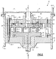
- the numeral 10 generally designates a low side hermetic scroll compressor.
- Compressor 10 has a shell or casing 12 having a main body 12-1 with an upper cover 12-2. Separator plate 14 divides the shell 12 into a suction plenum 16 and a discharge plenum 17.
- a crankcase 20 is welded or otherwise suitably secured within main body 12-1 and supports crankshaft 22 and Oldham coupling 24 in a conventional manner.
- Crankshaft 22 receives hub 26-2 of major or driving scroll 26 in eccentrically located recess 22-1.
- Major or driving scroll 26 is supported by crankcase 20 and coacts with Oldham coupling 24 in a conventional manner.
- Crankshaft 22 drives major or driving scroll 26 at a fixed radius.
- Major or driving scroll 26 has a wrap 26-1 which coacts with wrap 28-1 of minor or driven scroll 28.
- Major scroll 26, minor scroll 28 and Oldham coupling 24 are held in place between crankcase 20 and seal plate 30.
- pilot ring 32 surrounds scrolls 26 and 28 and is accurately secured to seal plate 30 by precision dowels 34 so that seal plate 30 and pilot ring 32 are, effectively, an integral structure.
- pilot ring 32 is accurately secured to crankcase 20 by precision dowels 21.
- pilot ring 32 and seal plate 30 can be parts of the same member thereby eliminating the need for dowels 34 and their associated bores.
- Minor scroll 28 has a base 28-2 having a plurality of circular recesses 28-3 formed therein. Preferably, there are three recesses 28-3 spaced 120° apart.
- Inner and outer annular recesses 28-4 and 28-5, respectively, are formed in the surface of base 28-2 and receive O-rings or other suitable seals 36 and 37, respectively.
- One or more restricted fluid passages 28-6 extend through base 28-2 from a point located between seals 36 and 37 and a point located between adjacent turns of wrap 28-1.
- a plurality of axially extending pins 40 corresponding in number and spacing to the centers of recesses 28-3 are located in bores 30-1 of seal plate 30.
- wrap 28-1 of scroll 28 is placed in engagement with wrap 26-1 of scroll 26. Seals 36 and 37 are put in place.
- pilot ring 32 is accurately located with respect to crankcase 20 by precision dowels 21.
- the seal plate 30 is set in place such that pins 40 are received in corresponding recesses 28-3 and is doweled to pilot ring 32 such that bores defined by bores 30-2, 32-2 and 20-1 are aligned to form a continuous bore and bolts 42 are threaded into the continuous bores.
- Discharge tube 44 is located and sealed in bore 30-3 and separator plate 14 is secured to discharge tube 44 and main body 12-1. Cover 12-2 is then sealed in place.
- major scroll 26 is capable of orbital movement in a circle having a radius equal to the distance between A-A the axis crankshaft 22 and B-B the axis of hub 26-2.
- Scroll 28 is capable of orbital movement through a circle having a diameter equal to the difference in diameters of recess 28-3 and pin 40 and a diameter equal to the difference in diameter between the base 28-2 and the corresponding portion of pilot ring 32 defined by annular surface 32-1.
- a motor (not illustrated) drives crankshaft 22 causing it to rotate about its axis A-A carrying eccentrically located hub 26-2 of major scroll 26.
- major scroll 26 coacts with Oldham coupling 24
- major scroll 26 is held to an orbiting motion when driven by crankshaft 22 with the radius of the orbit being equal to the distance between axes A-A and B-B.
- Wrap 26-1 of major scroll 26 coacts with wrap 28-1 of minor scroll 28 to trap volumes of gas from suction plenum 16 and compress the gas with the resultant compressed gas passing serially through discharge port 28-7, bore 30-3 and discharge tube 44 into discharge plenum 17 from which the compressed gas passes to the refrigeration system via an outlet (not illustrated).
- major scroll 26 is driven in a fixed orbiting motion. Responsive to the fluid pressure of the compression process, base 28-2 of minor scroll is forced into engagement with surface 32-1 of pilot ring 32 and maintains engagement while being held to a minor orbiting motion by pins 40. Minor scroll 28 is held in axial engagement with major scroll 26 by fluid pressure in chamber 50.
- seal plate 30 and pilot ring 32 can be portions of a single member thereby eliminating the need for dowels 34.
- seal plate 30 and pilot ring 32 can be portions of a single member thereby eliminating the need for dowels 34.
- major and minor scrolls have been used, their orbits can be the same or the "minor" orbit may be larger than the "major” orbit.
- chambers 50 can be located in seal plate 30 and pins 40 carried by scroll 28. It is therefore intended that the scope of the present invention is to be limited only by the scope of the appended claims.
Landscapes
- Engineering & Computer Science (AREA)
- Mechanical Engineering (AREA)
- General Engineering & Computer Science (AREA)
- Rotary Pumps (AREA)
Claims (6)
- Spiralmaschine mit:einem ersten Spiralteil (26), das eine Windung (26-1) hat;einer Einrichtung (24) zum Beschränken des ersten Spiralteils (26) auf eine Umlaufbewegung auf einer Umlaufbahn, die einen ersten Durchmesser hat;einem zweiten Spiralteil (28), das eine Windung (28-1) und eine Basis (28-2) hat und mit dem ersten Spiralteil (26) operativ in Berührung ist;einer radialen Bewegungsbegrenzungseinrichtung, die mit der Basis (28-2) zusammenwirkt, um die Radialbewegung der Basis (28-2) und dadurch des zweiten Spiralteils (28) zu begrenzen; undeiner axialen Nachgiebigkeitseinrichtung (28-6, 50), um das erste und zweite Spiralteil (24, 28) in Berührung zu halten, wodurch die radiale Bewegungsbegrenzungseinrichtung und die axiale Nachgiebigkeitseinrichtung (28-6) zusammenwirken, um das zweite Spiralteil (28) in axialer und radialer Berührung mit dem ersten Spiralteil (26) zu halten,dadurch gekennzeichnet, daß die radiale Bewegungsbegrenzungseinrichtung eine Steuerringeinrichtung (32) aufweist, die die Basis (28-2) mit einem radialen Spiel umgibt, um die radiale Bewegung der Basis (28-2) und dadurch des zweiten Spiralteils (28) auf eine vorbestimmte Distanz zu begrenzen, und eine Einrichtung (28-3, 40) zum Beschränken des zweiten Spiralteils (28) auf eine Umlaufbewegung auf einer Umlaufbahn, die einen zweiten Durchmesser hat, welcher gleich der vorbestimmten Distanz ist.
- Spiralmaschine nach Anspruch 1, dadurch gekennzeichnet, daß die Einrichtung zum Beschränken des zweiten Spiralteils (28) auf eine Umlaufbewegung mehrere Stifte (40) aufweist, die durch eine der Basis (28-2) überlagerte Dichtplatteneinrichtung (30) gehalten und in entsprechenden Ausnehmungen (28-3) in der Basis (28-2) aufgenommen sind, wobei die Stifte (40) und die Ausnehmungen (28-3) eine Differenz in den Durchmessern haben, die gleich dem radialen Spiel ist.
- Spiralmaschine nach Anspruch 2, dadurch gekennzeichnet, daß die axiale Nachgiebigkeitseinrichtung eine Fluiddruckkammer (50) aufweist, die zwischen der Dichtplatteneinrichtung (30) und der Basis (28-2) gebildet ist, und eine Fluidwegeinrichtung (28-6), welche die Fluiddruckkammer (50) mit einem Druckeinschlußraum verbindet, der zwischen den Windungen (26-1, 28-1) des ersten und zweiten Spiralteils (26, 28) gebildet ist.
- Spiralmaschine nach Anspruch 3, dadurch gekennzeichnet, daß die Einrichtung (28-3, 40) zum Beschränken des zweiten Spiralteils (28) auf eine Umlaufbewegung in der Fluiddruckkammer (50) angeordnet ist.
- Spiralmaschine nach Anspruch 2, 3 oder 4, gekennzeichnet weiter durch eine Kurbelwelleneinrichtung (22), welche das erste Spiralteil (26) antreibt und durch eine Kurbelgehäuseeinrichtung (20) gelagert ist, und durch eine Einrichtung (42), welche die Dichtplatteneinrichtung (30), die Steuerringeinrichtung (32) und die Kurbelgehäuseeinrichtung (20) als eine Einheit zusammenhält, welche das erste und zweite Spiralteil (26, 28) und die Einrichtungen (24; 28-3, 40) zum Beschränken des ersten und zweiten Spiralteils (26, 28) auf eine Umlaufbewegung enthält.
- Hermetische Niederdruckspiralkompressoreinrichtung, die eine Manteleinrichtung (12) und eine Spiralmaschine nach Anspruch 5 hat, wobei die Kurbelgehäuseeinrichtung (20) an der Manteleinrichtung (12) fest angebracht ist.
Applications Claiming Priority (2)
| Application Number | Priority Date | Filing Date | Title |
|---|---|---|---|
| US07/808,821 US5178526A (en) | 1991-12-17 | 1991-12-17 | Coupling mechanism for co-orbiting scroll members |
| US808821 | 1991-12-17 |
Publications (2)
| Publication Number | Publication Date |
|---|---|
| EP0548002A1 EP0548002A1 (de) | 1993-06-23 |
| EP0548002B1 true EP0548002B1 (de) | 1996-01-31 |
Family
ID=25199840
Family Applications (1)
| Application Number | Title | Priority Date | Filing Date |
|---|---|---|---|
| EP92630109A Expired - Lifetime EP0548002B1 (de) | 1991-12-17 | 1992-12-10 | Kupplungsmechanismus für eine Spiralmaschine |
Country Status (9)
| Country | Link |
|---|---|
| US (1) | US5178526A (de) |
| EP (1) | EP0548002B1 (de) |
| JP (1) | JP2703703B2 (de) |
| KR (1) | KR960009863B1 (de) |
| CN (1) | CN1031524C (de) |
| AU (1) | AU651509B2 (de) |
| CA (1) | CA2083526C (de) |
| DE (1) | DE69208065T2 (de) |
| TW (1) | TW223675B (de) |
Families Citing this family (27)
| Publication number | Priority date | Publication date | Assignee | Title |
|---|---|---|---|---|
| US5281114A (en) * | 1991-12-17 | 1994-01-25 | Carrier Corporation | Dynamically balanced co-orbiting scrolls |
| CN1042969C (zh) * | 1993-11-05 | 1999-04-14 | 三菱电机株式会社 | 涡旋压缩机 |
| JP3134656B2 (ja) * | 1994-03-18 | 2001-02-13 | 株式会社日立製作所 | スクロール圧縮機及びその組立て方法 |
| DE19528071A1 (de) * | 1995-07-31 | 1997-02-06 | Knorr Bremse Systeme | Spiralverdichter |
| EP0842363B1 (de) * | 1995-07-31 | 2002-12-04 | Knorr-Bremse Systeme für Schienenfahrzeuge GmbH | Spiralverdichter, insbesondere zum einsatz bei der drucklufterzeugung für schienenfahrzeuge |
| US5897306A (en) * | 1997-04-17 | 1999-04-27 | Copeland Corporation | Partition and pilot ring for scroll machine |
| US6095778A (en) * | 1998-06-01 | 2000-08-01 | Ford Motor Company | Scroll thrust bearing/coupling apparatus |
| US6142754A (en) * | 1998-06-29 | 2000-11-07 | Industrial Technology Research Institute | Mounting mechanism for a scroll machine |
| US20050260092A1 (en) * | 2003-10-29 | 2005-11-24 | Bolger Stephen R | Turbostatic compressor, pump, turbine and hydraulic motor and method of its operation |
| US7314357B2 (en) * | 2005-05-02 | 2008-01-01 | Tecumseh Products Company | Seal member for scroll compressors |
| ITRN20090011A1 (it) * | 2009-03-06 | 2010-09-07 | Leonardo Battistelli | Spirale rotante |
| US9080446B2 (en) * | 2012-03-23 | 2015-07-14 | Bitzer Kuehlmaschinenbau Gmbh | Scroll compressor with captured thrust washer |
| US9057269B2 (en) * | 2012-03-23 | 2015-06-16 | Bitzer Kuehlmaschinenbau Gmbh | Piloted scroll compressor |
| US9404491B2 (en) * | 2013-03-13 | 2016-08-02 | Agilent Technologies, Inc. | Scroll pump having bellows providing angular synchronization and back-up system for bellows |
| US9328730B2 (en) | 2013-04-05 | 2016-05-03 | Agilent Technologies, Inc. | Angular synchronization of stationary and orbiting plate scroll blades in a scroll pump using a metallic bellows |
| US9366255B2 (en) | 2013-12-02 | 2016-06-14 | Agilent Technologies, Inc. | Scroll vacuum pump having external axial adjustment mechanism |
| US9856874B2 (en) | 2014-09-26 | 2018-01-02 | Bitzer Kuehlmaschinenbau Gmbh | Holding plate for piloted scroll compressor |
| CN105822545A (zh) * | 2014-12-31 | 2016-08-03 | 丹佛斯(天津)有限公司 | 涡旋压缩机 |
| US11306717B2 (en) * | 2017-01-17 | 2022-04-19 | ECOLE POLYTECHNIQUE FéDéRALE DE LAUSANNE | Co-rotational scroll machine |
| US10995754B2 (en) | 2017-02-06 | 2021-05-04 | Emerson Climate Technologies, Inc. | Co-rotating compressor |
| US11111921B2 (en) | 2017-02-06 | 2021-09-07 | Emerson Climate Technologies, Inc. | Co-rotating compressor |
| CN112654787B (zh) * | 2018-09-05 | 2022-11-25 | 日立江森自控空调有限公司 | 共同旋转的涡旋压缩机的径向顺应性 |
| US11136977B2 (en) | 2018-12-31 | 2021-10-05 | Emerson Climate Technologies, Inc. | Compressor having Oldham keys |
| CN114729637B (zh) | 2019-11-15 | 2024-07-02 | 谷轮有限合伙公司 | 共旋转的涡旋式压缩机 |
| US11732713B2 (en) | 2021-11-05 | 2023-08-22 | Emerson Climate Technologies, Inc. | Co-rotating scroll compressor having synchronization mechanism |
| US12104594B2 (en) | 2021-11-05 | 2024-10-01 | Copeland Lp | Co-rotating compressor |
| US11624366B1 (en) | 2021-11-05 | 2023-04-11 | Emerson Climate Technologies, Inc. | Co-rotating scroll compressor having first and second Oldham couplings |
Family Cites Families (11)
| Publication number | Priority date | Publication date | Assignee | Title |
|---|---|---|---|---|
| US801182A (en) * | 1905-06-26 | 1905-10-03 | Leon Creux | Rotary engine. |
| US3874827A (en) * | 1973-10-23 | 1975-04-01 | Niels O Young | Positive displacement scroll apparatus with axially radially compliant scroll member |
| DE2831179A1 (de) * | 1978-07-15 | 1980-01-24 | Leybold Heraeus Gmbh & Co Kg | Verdraengermaschine nach dem spiralprinzip |
| JPS5540220A (en) * | 1978-09-14 | 1980-03-21 | Hitachi Ltd | Scroll fluid machinary |
| JPS58167893A (ja) * | 1982-03-29 | 1983-10-04 | Toyoda Autom Loom Works Ltd | 容積式流体圧縮装置 |
| JPS59115487A (ja) * | 1982-12-22 | 1984-07-03 | Mitsubishi Heavy Ind Ltd | 回転式流体機械 |
| JPS601395A (ja) * | 1983-06-17 | 1985-01-07 | Hitachi Ltd | スクロール圧縮機 |
| JPS623101A (ja) * | 1985-06-28 | 1987-01-09 | Shin Meiwa Ind Co Ltd | スクロ−ル形流体機械 |
| DE3604235C2 (de) * | 1986-02-11 | 1993-11-25 | Bosch Gmbh Robert | Spiralverdichter |
| DE3729319C2 (de) * | 1987-09-02 | 1995-11-16 | Bock Gmbh & Co Kaeltemaschinen | Spiralverdichter |
| JPH02161191A (ja) * | 1988-12-13 | 1990-06-21 | Sanden Corp | 密閉形スクロール型圧縮機 |
-
1991
- 1991-12-17 US US07/808,821 patent/US5178526A/en not_active Expired - Lifetime
-
1992
- 1992-11-16 TW TW081109140A patent/TW223675B/zh active
- 1992-11-23 CA CA002083526A patent/CA2083526C/en not_active Expired - Fee Related
- 1992-11-27 KR KR1019920022558A patent/KR960009863B1/ko not_active IP Right Cessation
- 1992-12-04 JP JP4325252A patent/JP2703703B2/ja not_active Expired - Fee Related
- 1992-12-10 EP EP92630109A patent/EP0548002B1/de not_active Expired - Lifetime
- 1992-12-10 DE DE69208065T patent/DE69208065T2/de not_active Expired - Fee Related
- 1992-12-16 CN CN92114894A patent/CN1031524C/zh not_active Expired - Fee Related
- 1992-12-16 AU AU30156/92A patent/AU651509B2/en not_active Ceased
Also Published As
| Publication number | Publication date |
|---|---|
| DE69208065T2 (de) | 1996-06-20 |
| AU651509B2 (en) | 1994-07-21 |
| CA2083526A1 (en) | 1993-06-18 |
| CN1074513A (zh) | 1993-07-21 |
| CN1031524C (zh) | 1996-04-10 |
| EP0548002A1 (de) | 1993-06-23 |
| JP2703703B2 (ja) | 1998-01-26 |
| US5178526A (en) | 1993-01-12 |
| JPH05248367A (ja) | 1993-09-24 |
| CA2083526C (en) | 1996-01-02 |
| KR960009863B1 (ko) | 1996-07-24 |
| DE69208065D1 (de) | 1996-03-14 |
| AU3015692A (en) | 1993-06-24 |
| TW223675B (de) | 1994-05-11 |
Similar Documents
| Publication | Publication Date | Title |
|---|---|---|
| EP0548002B1 (de) | Kupplungsmechanismus für eine Spiralmaschine | |
| EP0548003B1 (de) | Oldham's Kupplung für Spiralverdichter | |
| EP0107409B1 (de) | Kompressor der Spiralbauart mit Schmiersystem | |
| US4753582A (en) | Scroll compressor with control of distance between driving and driven scroll axes | |
| EP0009350B1 (de) | Kompressoren des Exzenterspiraltyps | |
| EP0211672B1 (de) | Spiralverdichter mit Einrichtung zur Verdrängungsregelung | |
| US8226387B2 (en) | Scroll compressor including lubrication features | |
| EP0105684B1 (de) | Kühlkompressor der Spiralbauart mit Spiralbauteil | |
| EP0584036B1 (de) | Dynamisch ausgeglichene Verdrängermaschine nach dem Spiralprinzip | |
| US4900238A (en) | Scroll type compressor with releasably secured hermetic housing | |
| EP0012616A1 (de) | Kompressor mit ineinandergreifenden Spiralelementen | |
| EP0099740B1 (de) | Fluidumverdrängungsmaschine mit Exzenterspiralelementen und Montageverfahren | |
| EP0548001B1 (de) | Verfahren zum Auswuchten einer Oldham's Kupplung für Spiralverdichter | |
| US4548555A (en) | Scroll type fluid displacement apparatus with nonuniform scroll height | |
| US4477239A (en) | Scroll type fluid displacement apparatus with offset wraps for reduced housing diameter | |
| EP0069531A2 (de) | Kompressor vom Spiraltyp mit verbessertem Auslassmechismus | |
| EP0012614A1 (de) | Verbesserungen an Fluidumkompressoren mit ineinandergreifenden Spiralvorsprüngen | |
| CA1305688C (en) | Scroll type compressor | |
| EP0558167B1 (de) | Verdrängermaschine nach dem Spiralprinzip | |
| EP0240739A1 (de) | Spiralverdichterschmiersystem | |
| KR19990055247A (ko) | 스크롤형 유체기계 |
Legal Events
| Date | Code | Title | Description |
|---|---|---|---|
| PUAI | Public reference made under article 153(3) epc to a published international application that has entered the european phase |
Free format text: ORIGINAL CODE: 0009012 |
|
| AK | Designated contracting states |
Kind code of ref document: A1 Designated state(s): CH DE FR GB IT LI SE |
|
| 17P | Request for examination filed |
Effective date: 19930819 |
|
| 17Q | First examination report despatched |
Effective date: 19941013 |
|
| GRAA | (expected) grant |
Free format text: ORIGINAL CODE: 0009210 |
|
| AK | Designated contracting states |
Kind code of ref document: B1 Designated state(s): CH DE FR GB IT LI SE |
|
| PG25 | Lapsed in a contracting state [announced via postgrant information from national office to epo] |
Ref country code: IT Free format text: LAPSE BECAUSE OF FAILURE TO SUBMIT A TRANSLATION OF THE DESCRIPTION OR TO PAY THE FEE WITHIN THE PRESCRIBED TIME-LIMIT;WARNING: LAPSES OF ITALIAN PATENTS WITH EFFECTIVE DATE BEFORE 2007 MAY HAVE OCCURRED AT ANY TIME BEFORE 2007. THE CORRECT EFFECTIVE DATE MAY BE DIFFERENT FROM THE ONE RECORDED. Effective date: 19960131 |
|
| ET | Fr: translation filed | ||
| REF | Corresponds to: |
Ref document number: 69208065 Country of ref document: DE Date of ref document: 19960314 |
|
| PG25 | Lapsed in a contracting state [announced via postgrant information from national office to epo] |
Ref country code: SE Effective date: 19960430 |
|
| PLBE | No opposition filed within time limit |
Free format text: ORIGINAL CODE: 0009261 |
|
| STAA | Information on the status of an ep patent application or granted ep patent |
Free format text: STATUS: NO OPPOSITION FILED WITHIN TIME LIMIT |
|
| PG25 | Lapsed in a contracting state [announced via postgrant information from national office to epo] |
Ref country code: GB Effective date: 19961210 |
|
| PG25 | Lapsed in a contracting state [announced via postgrant information from national office to epo] |
Ref country code: LI Effective date: 19961231 Ref country code: CH Effective date: 19961231 |
|
| 26N | No opposition filed | ||
| GBPC | Gb: european patent ceased through non-payment of renewal fee |
Effective date: 19961210 |
|
| REG | Reference to a national code |
Ref country code: CH Ref legal event code: PL |
|
| PGFP | Annual fee paid to national office [announced via postgrant information from national office to epo] |
Ref country code: DE Payment date: 19991210 Year of fee payment: 8 |
|
| PG25 | Lapsed in a contracting state [announced via postgrant information from national office to epo] |
Ref country code: FR Free format text: LAPSE BECAUSE OF NON-PAYMENT OF DUE FEES Effective date: 20010831 |
|
| REG | Reference to a national code |
Ref country code: FR Ref legal event code: ST |
|
| PG25 | Lapsed in a contracting state [announced via postgrant information from national office to epo] |
Ref country code: DE Free format text: LAPSE BECAUSE OF NON-PAYMENT OF DUE FEES Effective date: 20011002 |
|
| PGFP | Annual fee paid to national office [announced via postgrant information from national office to epo] |
Ref country code: FR Payment date: 20011130 Year of fee payment: 10 |