EP0547407A1 - Druckluft-Bremsanlage, insbesondere für Nutzfahrzeuge - Google Patents
Druckluft-Bremsanlage, insbesondere für Nutzfahrzeuge Download PDFInfo
- Publication number
- EP0547407A1 EP0547407A1 EP92119947A EP92119947A EP0547407A1 EP 0547407 A1 EP0547407 A1 EP 0547407A1 EP 92119947 A EP92119947 A EP 92119947A EP 92119947 A EP92119947 A EP 92119947A EP 0547407 A1 EP0547407 A1 EP 0547407A1
- Authority
- EP
- European Patent Office
- Prior art keywords
- valve
- control
- brake
- line
- compressed air
- Prior art date
- Legal status (The legal status is an assumption and is not a legal conclusion. Google has not performed a legal analysis and makes no representation as to the accuracy of the status listed.)
- Granted
Links
Images

Classifications
-
- B—PERFORMING OPERATIONS; TRANSPORTING
- B60—VEHICLES IN GENERAL
- B60T—VEHICLE BRAKE CONTROL SYSTEMS OR PARTS THEREOF; BRAKE CONTROL SYSTEMS OR PARTS THEREOF, IN GENERAL; ARRANGEMENT OF BRAKING ELEMENTS ON VEHICLES IN GENERAL; PORTABLE DEVICES FOR PREVENTING UNWANTED MOVEMENT OF VEHICLES; VEHICLE MODIFICATIONS TO FACILITATE COOLING OF BRAKES
- B60T13/00—Transmitting braking action from initiating means to ultimate brake actuator with power assistance or drive; Brake systems incorporating such transmitting means, e.g. air-pressure brake systems
- B60T13/10—Transmitting braking action from initiating means to ultimate brake actuator with power assistance or drive; Brake systems incorporating such transmitting means, e.g. air-pressure brake systems with fluid assistance, drive, or release
- B60T13/66—Electrical control in fluid-pressure brake systems
- B60T13/68—Electrical control in fluid-pressure brake systems by electrically-controlled valves
- B60T13/683—Electrical control in fluid-pressure brake systems by electrically-controlled valves in pneumatic systems or parts thereof
-
- B—PERFORMING OPERATIONS; TRANSPORTING
- B60—VEHICLES IN GENERAL
- B60T—VEHICLE BRAKE CONTROL SYSTEMS OR PARTS THEREOF; BRAKE CONTROL SYSTEMS OR PARTS THEREOF, IN GENERAL; ARRANGEMENT OF BRAKING ELEMENTS ON VEHICLES IN GENERAL; PORTABLE DEVICES FOR PREVENTING UNWANTED MOVEMENT OF VEHICLES; VEHICLE MODIFICATIONS TO FACILITATE COOLING OF BRAKES
- B60T8/00—Arrangements for adjusting wheel-braking force to meet varying vehicular or ground-surface conditions, e.g. limiting or varying distribution of braking force
- B60T8/32—Arrangements for adjusting wheel-braking force to meet varying vehicular or ground-surface conditions, e.g. limiting or varying distribution of braking force responsive to a speed condition, e.g. acceleration or deceleration
- B60T8/321—Arrangements for adjusting wheel-braking force to meet varying vehicular or ground-surface conditions, e.g. limiting or varying distribution of braking force responsive to a speed condition, e.g. acceleration or deceleration deceleration
- B60T8/3255—Systems in which the braking action is dependent on brake pedal data
- B60T8/327—Pneumatic systems
-
- B—PERFORMING OPERATIONS; TRANSPORTING
- B60—VEHICLES IN GENERAL
- B60T—VEHICLE BRAKE CONTROL SYSTEMS OR PARTS THEREOF; BRAKE CONTROL SYSTEMS OR PARTS THEREOF, IN GENERAL; ARRANGEMENT OF BRAKING ELEMENTS ON VEHICLES IN GENERAL; PORTABLE DEVICES FOR PREVENTING UNWANTED MOVEMENT OF VEHICLES; VEHICLE MODIFICATIONS TO FACILITATE COOLING OF BRAKES
- B60T8/00—Arrangements for adjusting wheel-braking force to meet varying vehicular or ground-surface conditions, e.g. limiting or varying distribution of braking force
- B60T8/32—Arrangements for adjusting wheel-braking force to meet varying vehicular or ground-surface conditions, e.g. limiting or varying distribution of braking force responsive to a speed condition, e.g. acceleration or deceleration
- B60T8/34—Arrangements for adjusting wheel-braking force to meet varying vehicular or ground-surface conditions, e.g. limiting or varying distribution of braking force responsive to a speed condition, e.g. acceleration or deceleration having a fluid pressure regulator responsive to a speed condition
- B60T8/36—Arrangements for adjusting wheel-braking force to meet varying vehicular or ground-surface conditions, e.g. limiting or varying distribution of braking force responsive to a speed condition, e.g. acceleration or deceleration having a fluid pressure regulator responsive to a speed condition including a pilot valve responding to an electromagnetic force
- B60T8/361—Arrangements for adjusting wheel-braking force to meet varying vehicular or ground-surface conditions, e.g. limiting or varying distribution of braking force responsive to a speed condition, e.g. acceleration or deceleration having a fluid pressure regulator responsive to a speed condition including a pilot valve responding to an electromagnetic force wherein the pilot valve is mounted in a circuit controlling an auxiliary fluid system
-
- B—PERFORMING OPERATIONS; TRANSPORTING
- B60—VEHICLES IN GENERAL
- B60T—VEHICLE BRAKE CONTROL SYSTEMS OR PARTS THEREOF; BRAKE CONTROL SYSTEMS OR PARTS THEREOF, IN GENERAL; ARRANGEMENT OF BRAKING ELEMENTS ON VEHICLES IN GENERAL; PORTABLE DEVICES FOR PREVENTING UNWANTED MOVEMENT OF VEHICLES; VEHICLE MODIFICATIONS TO FACILITATE COOLING OF BRAKES
- B60T8/00—Arrangements for adjusting wheel-braking force to meet varying vehicular or ground-surface conditions, e.g. limiting or varying distribution of braking force
- B60T8/32—Arrangements for adjusting wheel-braking force to meet varying vehicular or ground-surface conditions, e.g. limiting or varying distribution of braking force responsive to a speed condition, e.g. acceleration or deceleration
- B60T8/34—Arrangements for adjusting wheel-braking force to meet varying vehicular or ground-surface conditions, e.g. limiting or varying distribution of braking force responsive to a speed condition, e.g. acceleration or deceleration having a fluid pressure regulator responsive to a speed condition
- B60T8/48—Arrangements for adjusting wheel-braking force to meet varying vehicular or ground-surface conditions, e.g. limiting or varying distribution of braking force responsive to a speed condition, e.g. acceleration or deceleration having a fluid pressure regulator responsive to a speed condition connecting the brake actuator to an alternative or additional source of fluid pressure, e.g. traction control systems
- B60T8/4809—Traction control, stability control, using both the wheel brakes and other automatic braking systems
- B60T8/4818—Traction control, stability control, using both the wheel brakes and other automatic braking systems in pneumatic brake systems
Definitions
- the invention relates to a compressed air brake system according to the preamble of the main claim.
- Such a brake system is already known from DE 32 19 140 A1, in which the electrical part of the brake value transmitter is used to control an electrical primary control circuit of the brake system, while the pneumatic part of the brake value transmitter is assigned to a pneumatic secondary control circuit.
- the primary control circuit is characterized by fast electropneumatic brake pressure control and, with appropriately trained control electronics, allows anti-lock and traction control operations.
- the secondary control circuit on the other hand, primarily serves to ensure the failure safety of the brake system.
- a relay valve is provided in a brake line to control compressed air in one or more brake cylinders of the brake system.
- a control chamber of the relay valve can be controlled both via the primary control circuit and the secondary control circuit, specifically via a solenoid valve of a control line of the secondary control circuit which is designed as a shut-off valve.
- This solenoid valve assumes its spring-operated open position for brake pressure build-up.
- For Brake pressure maintenance and reduction can be switched into its magnetically operated blocking position by the control electronics.
- the solenoid valve can hold back the control pressure in the control chamber of the relay valve for several seconds in the pressure reduction and hold phase under unfavorable conditions.
- the compressed air brake system according to the invention with the characterizing features of the main claim has the advantage that, with effective electro-pneumatic brake actuation, the control air is fed into the control chamber of the relay valve over a short distance, which is conducive to the instantaneous build-up of brake pressure. If the brake signal generated by the electrical part of the brake value transmitter disappears during an anti-lock control system, an immediate release of the brake is also advantageously achieved. Overall, the dynamics of the brake system are improved.
- valve arrangements disclosed in the two subclaims 2 and 3 are particularly advantageous because the same magnetic actuations for brake pressure maintenance and reduction are always controlled during the anti-lock control operation, regardless of whether this control operation is performed when the brake is actuated by the electrical or the pneumatic part of the brake value transmitter he follows. It is advantageous in the embodiment according to claim 3 that the activation of a maximum of one magnet actuation is required.
- the measure specified in claim 4 is advantageous because it closes the control circuit during the electro-pneumatic brake actuation.
- the embodiment characterized in claim 5 fulfills the same purpose in the case of an anti-lock and traction control system.
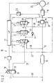
- FIG. 1 shows a section of a functional diagram of an electropneumatically or pneumatically actuated compressed air brake system with a relay valve that can be controlled by solenoid valves
- FIG. 2 shows a corresponding illustration with solenoid valves that differ from FIG.
- the first exemplary embodiment of a compressed air brake system 10 for commercial vehicles shown in FIG. 1 represents the activation of only one brake cylinder 11 in a brake line 12.
- the brake system 10 is of course used to actuate further brake cylinders, not shown, of the commercial vehicle.
- a compressed air reservoir 13 In the brake line 12 there is a compressed air reservoir 13.
- a relay valve 14 For monitoring the brake line 12, a relay valve 14, not shown in detail, is located between the reservoir 13 and the brake cylinder 11 for example of the type known from DE 32 40 274 C2.
- the brake system 10 has a pedal-operated, two-circuit brake value transmitter 17 with an electrical part 18 and a pneumatic part 19.
- Control unit 20 and control electronics 21 of an electrical primary control circuit for electropneumatic brake actuation, anti-lock and traction control operation are connected on the electrical part 18 of the brake value transmitter 17
- the control electronics 21 are used to actuate the solenoid valves described later in a pressure control unit 22 with a dash-dotted line in the drawing.
- a pressure sensor 23 which detects the brake pressure in the brake cylinder 11 and a rotational speed sensor 25 monitoring the rotational behavior of a vehicle wheel 24 braked by the brake cylinder 11 are connected to the control electronics 21.
- the pneumatic part 19 of the brake value transmitter 17 lies in a control line 28 of a pneumatic secondary control circuit of the brake system 10, branched off from the brake line 12 and supplied from the compressed air reservoir 13.
- the control line 28 leads to a control chamber 29 of the relay valve 14 integrated in the pressure control unit 22
- the pneumatic part 19 of the brake value transmitter 17, which has a pressure relief point 30, and the control chamber 29 of the relay valve 14, a changeover valve 31 are arranged in the control line 28 and a shutoff valve 32 is arranged downstream thereof.
- the switching valve 31 is designed as a 3/2-way valve. It has a spring-operated basic position 0, in which the control line 28 is switched through. In contrast, in a solenoid-operated working position I of the changeover valve 31, a supply line 35, which branches off from the brake line 12 between the compressed air supply container 13 and the relay valve 14, is connected to the downstream part of the control line 28. In the basic position 0 of the changeover valve 31, the supply line 35 is shut off; the upstream part of the control line 28 is also blocked in the working position I of the changeover valve 31.
- the shut-off valve 32 has the design of a 2/2-way valve. In its spring-operated open position 0, it switches through the control line 28; in the solenoid-operated blocking position I, however, the control line 28 is interrupted.
- a ventilation line 38 branches off from the control line 28, which leads to a pressure relief point 39 of the relay valve 14.
- An outlet valve 40 of the pressure control unit 22 is arranged in the vent line 38.
- the outlet valve 40 is designed as a 2/2-way valve: in its spring-operated blocking position 0, it interrupts the ventilation line 28, in the solenoid-operated opening position I the ventilation line 38 is switched on.
- a bypass line 43 is integrated in the pressure control unit 22. This bridges the shut-off valve 32 in the control line 28, i.e. the bypass line 43 is connected on the one hand between the changeover valve 31 and the shutoff valve 32 and on the other hand between the shutoff valve 32 and the control chamber 29 of the relay valve 14 to the control line 28.
- a check valve 44 is arranged in the bypass line 43 and opens in the flow direction from the control chamber 29 of the relay valve 14 to the changeover valve 31.
- the pressure controlled by the shut-off valve 32 and the outlet valve 40 in accordance with the electrical brake signal loads in the relay valve 14 a control piston for the actuation of a double seat valve, which monitors the connection between the compressed air reservoir 13 and the brake cylinder 11 or between the latter and the pressure relief point 39 on both sides of a closed position .
- the brake pressure controlled by the relay valve 14 is in turn monitored by the pressure sensor 23 and corrected in the event of deviations from the control electronics 21 by corresponding switching signals to the shut-off valve 32 and the outlet valve 40.
- control electronics 21 switches the shut-off valve 32 and the outlet valve 40 according to predetermined control algorithms for generating phases for brake pressure reduction, pressure maintenance and pressure build-up in the brake cylinder 11 in order to stabilize the vehicle wheel 24.
- control electronics 21 If impermissibly large drive slip occurs on the vehicle wheel 24 when the commercial vehicle starts up and accelerates, this is also recognized by the control electronics 21 on the basis of the signals from the speed sensor 25.
- the control electronics 21 then switch the changeover valve 31 to the working position I in order to supply the control line 28 with compressed air.
- the shut-off valve 32 and the outlet valve 40 are switched to generate phases for brake pressure build-up, pressure maintenance and pressure reduction in the brake cylinder 11.
- the pressure control unit 22 can be used in the braking system of a towing vehicle (as shown) and / or on a trailer vehicle. Activation of the relay valve 14 is also possible when there is no electrical brake signal, be it that the towing vehicle does not provide an electrical signal for the pressure control unit 22 located on the trailer vehicle or that the transmission of the electrical signal is not possible is what is recognized by the control unit 20 and / or the control electronics 21.
- the control electronics 21 therefore do not control the changeover valve 31, i.e. this remains in the basic position 0 just like the valves 32 and 40. Nevertheless, the braking ability of the compressed air brake system 10 is given, specifically via the pneumatic secondary control circuit also referred to as a retention circuit.
- the pneumatic brake signal which is actuated by the pneumatic part 19 when the brake value transmitter 17 is actuated, is fed through the control line 28 into the control chamber 29 of the relay valve 14 and the brake cylinder 11 is acted upon by the relay valve 14 with brake pressure.
- This can relate to pressure reduction the following
- the pressure hold phase, in which the shut-off valve 32 takes its locking position I and the exhaust valve 40 takes its locking position 0, can last for several seconds if an extremely low coefficient of friction on the road surface and a relatively large moment of inertia of the vehicle wheel 24 decelerates its acceleration.
- the second exemplary embodiment of the compressed air brake system 10 shown in FIG. 2 differs from the first one essentially in that a pressure control unit 22 'is equipped with a second changeover valve 47 which is arranged downstream of the shut-off valve 32 in the control line 28 and which functions as the outlet valve 40 of the with the first embodiment.
- the second switch valve 47 is a 3/2-way valve. In its spring-operated basic position 0, it switches through the control line 28 to the control chamber 29 of the relay valve 14. In its solenoid-operated working position I, the part of the control line 28 on the control chamber side is connected to the vent line 38 leading to the pressure relief point 39 of the relay valve 14.
- the connection of the vent line 38 is released, in the working position I the connection of the control line 28 is interrupted.
- the bypass line 43 bridges both the shut-off valve 32 and the second changeover valve 47 in the control line 28.
- shut-off valve 32 and the second switching valve 47 11 phases for pressure build-up, pressure maintenance and pressure reduction are in the brake cylinder switchable. No electrical control of the shut-off valve 32 and the second changeover valve 47 is required for brake pressure build-up. For pressure maintenance, only the shut-off valve 32 is to be switched to the solenoid-operated blocking position I. To lower the pressure, it is only necessary to switch the second changeover valve 47 into the solenoid-operated working position I.
- electropneumatic or purely pneumatic brake actuation and anti-lock and traction control operation are possible in a corresponding manner in the first exemplary embodiment.
Landscapes
- Engineering & Computer Science (AREA)
- Physics & Mathematics (AREA)
- Transportation (AREA)
- Mechanical Engineering (AREA)
- Fluid Mechanics (AREA)
- Electromagnetism (AREA)
- Braking Systems And Boosters (AREA)
- Regulating Braking Force (AREA)
Abstract
Description
- Die Erfindung geht aus von einer Druckluft-Bremsanlage nach der Gattung des Hauptanspruchs.
- Es ist schon eine solche Bremsanlage aus DE 32 19 140 A1 bekannt, bei welcher der elektrische Teil des Bremswertgebers der Ansteuerung eines elektrischen Primärsteuerkreises der Bremsanlage dient, während der pneumatische Teil des Bremswertgebers einem pneumatischen Sekundärsteuerkreis zugeordnet ist. Der Primärsteuerkreis zeichnet sich durch eine schnelle elektropneumatische Bremsdruckregelung aus und gestattet mit entsprechend ausgebildeter Regelelektronik Blockierschutz- und Antriebsschlupf-Regelbetrieb. Der Sekundärsteuerkreis dient dagegen in erster Linie der Ausfallsicherheit der Bremsanlage.
- Zur Einsteuerung von Druckluft in einen oder mehrere Bremszylinder der Bremsanlage ist ein Relaisventil in einer Bremsleitung vorgesehen. Eine Steuerkammer des Relaisventils ist sowohl über den Primärsteuerkreis als auch den Sekundärsteuerkreis ansteuerbar, und zwar über ein als Absperrventil ausgebildetes Magnetventil einer Steuerleitung des Sekundärsteuerkreises. Dieses Magnetventil nimmt für Bremsdruckaufbau seine federbetätigte Durchlaßstellung ein. Für Bremsdruckhalten und -abbau ist es von der Regelelektronik in seine magnetbetätigte Sperrstellung schaltbar. Bei einer Blockierschutzregelung kann das Magnetventil unter ungünstigen Bedingungen den Steuerdruck in der Steuerkammer des Relaisventils in der Druckabbau- und -haltephase mehrere Sekunden lang zurückhalten. Trotz eines Abbrechens des Bremsvorganges durch den Fahrzeugführer kann es daher zu einem verzögerten Lösen der Bremsen kommen, nämlich erst dann, wenn die Regelelektronik eine Druckaufbauphase schaltet und sich die Steuerkammer des Relaisventils über die Steuerleitung und die Entlastungsstelle des Bremswertgebers entlüften kann.
- Die erfindungsgemäße Druckluft-Bremsanlage mit den kennzeichnenden Merkmalen des Hauptanspruchs hat demgegenüber den Vorteil, daß bei wirksamer elektropneumatischer Bremsbetätigung die Steuerluft auf kurzem Wege in die Steuerkammer des Relaisventils eingesteuert wird, was für den unverzögerten Bremsdruckaufbau förderlich ist. Beim Fortfall des vom elektrischen Teil des Bremswertgebers erzeugten Bremssignals während einer Blockierschutzregelung wird vorteilhafterweise außerdem ein sofortiges Lösen der Bremse erzielt. Insgesamt wird die Dynamik der Bremsanlage verbessert.
- Durch die in den Unteransprüchen aufgeführten Maßnahmen sind vorteilhafte Weiterbildungen und Verbesserungen der im Hauptanspruch angegebenen Druckluft-Bremsanlage möglich.
- Besonders vorteilhaft sind die in den beiden Unteransprüchen 2 und 3 offenbarten Ventilanordnungen, weil stets die gleichen Magnetbetätigungen für Bremsdruckhalten und -abbau während des Blockierschutz-Regelbetriebes angesteuert werden, unabhängig davon, ob dieser Regelvorgang bei einer Bremsbetätigung durch den elektrischen oder den pneumatischen Teil des Bremswertgebers erfolgt. Dabei ist bei der Ausgestaltung gemäß Anspruch 3 von Vorteil, daß die Ansteuerung maximal einer Magnetbetätigung erforderlich ist.
- Desweiteren ist die im Anspruch 4 angegebene Maßnahme vorteilhaft, weil hierdurch bei der elektropneumatischen Bremsbetätigung der Regelkreis geschlossen wird.
- Den gleichen Zweck erfüllt die im Anspruch 5 gekennzeichnete Ausgestaltung bei einer Blockierschutz- und Antriebsschlupfregelung.
- Zwei Ausführungsbeispiele der Erfindung sind in der Zeichnung vereinfacht dargestellt und in der nachfolgenden Beschreibung näher erläutert. Es zeigen Figur 1 einen Ausschnitt eines Funktionsschemas einer elektropneumatisch oder pneumatisch betätigbaren Druckluft-Bremsanlage mit einem durch Magnetventile ansteuerbarem Relaisventil und Figur 2 eine entsprechende Darstellung mit von Figur 1 abweichend ausgewählten Magnetventilen.
- Das in Figur 1 dargestellte erste Ausführungsbeispiel einer Druckluft-Bremsanlage 10 für Nutzfahrzeuge gibt die Ansteuerung lediglich eines Bremszylinders 11 in einer Bremsleitung 12 wieder. (Die Bremsanlage 10 dient selbstverständlich der Betätigung weiterer, nicht dargestellter Bremszylinder des Nutzfahrzeugs.) In der Bremsleitung 12 befindet sich ein Druckluft-Vorratsbehälter 13. Für die Überwachung der Bremsleitung 12 ist zwischen dem Vorratsbehälter 13 und dem Bremszylinder 11 ein nicht detailliert dargestellten Relaisventil 14 beispielsweise der aus DE 32 40 274 C2 bekannten Art angeordnet.
- Die Bremsanlage 10 besitzt einen pedalbetätigbaren, zweikreisigen Bremswertgeber 17 mit einem elektrischen Teil 18 und einem pneumatischen Teil 19. An den elektrischen Teil 18 des Bremswertgebers 17 sind ein Steuergerät 20 und eine Regelelektronik 21 eines elektrischen Primärsteuerkreises für elektropneumatische Bremsbetätigung, Blockierschutz- und Antriebsschlupf-Regelbetrieb angeschlossen. Die Regelelektronik 21 dient der Ansteuerung später beschriebenen Magnetventile einer in der Zeichnung strichpunktiert umrandeten Drucksteuereinheit 22. Außerdem sind an die Regelelektronik 21 ein den Bremsdruck im Bremszylinder 11 erfassender Drucksensor 23 sowie ein das Drehverhalten eines vom Bremszylinder 11 abgebremsten Fahrzeugrades 24 überwachender Drehzahlsensor 25 angeschlossen.
- Der pneumatische Teil 19 des Bremswertgebers 17 liegt in einer von der Bremsleitung 12 abgezweigten, aus den Druckluft-Vorratsbehälter 13 versorgten Steuerleitung 28 eines pneumatischen Sekundärsteuerkreises der Bremsanlage 10. Die Steuerleitung 28 führt zu einer Steuerkammer 29 des in die Drucksteuereinheit 22 integrierten Relaisventils 14. Zwischen dem eine Druckentlastungsstelle 30 aufweisenden pneumatischen Teil 19 des Bremswertgebers 17 und der Steuerkammer 29 des Relaisventils 14 sind in der Steuerleitung 28 ein Umschaltventil 31 und stromabwärts von diesem ein Absperrventil 32 angeordnet.
- Das Umschaltventil 31 ist als 3/2-Wegeventil ausgebildet. Es besitzt eine federbetätigte Grundstellung 0, in welcher die Steuerleitung 28 durchgeschaltet ist. In einer magnetbetätigten Arbeitsstellung I des Umschaltventils 31 ist dagegen eine Vorratsleitung 35, welche zwischen dem Druckluft-Vorratsbehälter 13 und dem Relaisventil 14 von der Bremsleitung 12 abzweigt, mit dem stromabwärtigen Teil der Steuerleitung 28 verbunden. In der Grundstellung 0 des Umschaltventils 31 ist die Vorratsleitung 35 abgesperrt; gleichfalls abgesperrt ist der stromaufwärtige Teil der Steuerleitung 28 in der Arbeitsstellung I des Umschaltventils 31.
- Das Absperrventil 32 besitzt die Bauform eines 2/2-Wegeventils. In seiner federbetätigten Durchlaßstellung 0 schaltet es die Steuerleitung 28 durch; in der magnetbetätigten Sperrstellung I ist die Steuerleitung 28 dagegen unterbrochen.
- Zwischen dem Absperrventil 32 und dem Relaisventil 14 zweigt von der Steuerleitung 28 eine Entlüftungsleitung 38 ab, welche zu einer Druckentlastungsstelle 39 des Relaisventils 14 führt. In der Entlüftungsleitung 38 ist ein Auslaßventil 40 der Drucksteuereinheit 22 angeordnet. Das Auslaßventil 40 ist als 2/2-Wegeventil ausgebildet: In seiner federbetätigten Sperrstellung 0 unterbricht es die Entlüftungsleitung 28, in der magnetbetätigten Durchlaßstellung I ist die Entlüftungsleitung 38 durchgeschaltet.
- Außerdem ist in der Drucksteuereinheit 22 eine Bypassleitung 43 integriert. Diese überbrückt das Absperrventil 32 in der Steuerleitung 28, d.h. die Bypassleitung 43 ist einerseits zwischen dem Umschaltventil 31 und dem Absperrventil 32 und andererseits zwischen dem Absperrventil 32 und der Steuerkammer 29 des Relaisventils 14 an die Steuerleitung 28 angeschlossen. In der Bypassleitung 43 ist ein Rückschlagventil 44 angeordnet, welches in Strömungsrichtung von der Steuerkammer 29 des Relaisventils 14 zum Umschaltventil 31 öffnet.
- Bei einer Betätigung des Bremswertgebers 17 werden im elektrischen Teil 18 ein elektrisches Bremssignal, im pneumatischen Teil 19 ein pneumatisches Bremssignal erzeugt. Das schnellere elektrische Signal wird im Steuergerät 20 und in der Regelelektronik 21 verarbeitet, welche das Umschaltventil 31 in die Arbeitsstellung I schaltet. Unter Umgehung des pneumatischen Teils 19 des Bremswertgebers 17 wird nun dem Vorratsbehälter 13 Druckluft entnommen und durch die Vorratsleitung 35 in den auf das Umschaltventil 31 folgenden, stromabwärtigen Teil der Steuerleitung 28 eingesteuert. Die Regelelektronik 21 bemißt den in die Steuerkammer 29 des Relaisventils 14 einzusteuernden Druck entsprechend dem Signal des elektrischen Teils 18 des Bremswertgebers 17 durch entsprechendes Schalten des Absperrventils 32 in der Steuerleitung 28 und des Auslaßventils 40 in der Entlüftungsleitung 38. Dabei nehmen für Bremsdruckaufbau das Absperrventil 32 seine Durchlaßstellung 0 und das Auslaßventil 40 seine Sperrstellung 0 ein. Für Druckhalten wird das Absperrventil 32 in seine Sperrstellung I geschaltet, während das Auslaßventil 40 in der Sperrstellung 0 verbleibt. Für Druckabbau werden das Absperrventil 32 in die Sperrstellung I und das Auslaßventil 40 in die Durchlaßstellung I geschaltet.
- Der vom Absperrventil 32 und vom Auslaßventil 40 entsprechend dem elektrischen Bremssignal ausgesteuerte Druck belastet im Relaisventil 14 einen Steuerkolben für die Betätigung eines Doppelsitzventils, welches beiderseits einer Abschlußstellung die Verbindung zwischen dem Druckluft-Vorratsbehälter 13 und dem Bremszylinder 11 oder zwischen diesem und der Druckentlastungsstelle 39 überwacht. Der vom Relaisventil 14 ausgesteuerte Bremsdruck wiederum wird vom Drucksensor 23 überwacht und bei Abweichungen von der Regelelektronik 21 durch entsprechende Schaltsignale an das Absperrventil 32 und das Auslaßventil 40 korrigiert.
- Droht bei einer Bremsung das Fahrzeugrad 24 zu blockieren, so wird dieses von der Regelelektronik 21 aufgrund der Signale des Drehzahlsensors 25 erkannt. Die Regelelektronik 21 schaltet das Absperrventil 32 und das Auslaßventil 40 entsprechend vorgegebenen Regelalgorythmen zur Erzeugung von Phasen für Bremsdruckabbau, Druckhalten und Druckaufbau im Bremszylinder 11, um das Fahrzeugrad 24 zu stabilisieren.
- Tritt beim Anfahren und Beschleunigen des Nutzfahrzeugs am Fahrzeugrad 24 unzulässig großer Antriebsschlupf auf, so wird dies von der Regelelektronik 21 ebenfalls aufgrund der Signale des Drehzahlsensors 25 erkannt. Die Regelelektronik 21 schaltet dann das Umschaltventil 31 in die Arbeitsstellung I, um die Steuerleitung 28 mit Druckluft zu versorgen. Außerdem werden, wie vorstehend beschrieben, das Absperrventil 32 und das Auslaßventil 40 geschaltet, um im Bremszylinder 11 Phasen für Bremsdruckaufbau, Druckhalten und Druckabbau zu erzeugen.
- Die Drucksteuereinheit 22 kann Verwendung finden in der Bremsanlage eines Zugfahrzeugs (wie dargestellt) und/oder auf einem Anhängefahrzeug. Dabei ist eine Ansteuerung des Relaisventils 14 auch dann möglich, wenn kein elektrisches Bremssignal vorliegt, sei es, daß das Zugfahrzeug für die auf dem Anhängefahrzeug befindliche Drucksteuereinheit 22 kein elektrisches Signal zur Verfügung stellt, oder sei es, daß die Übertragung des elektrischen Signals nicht möglich ist, was vom Steuergerät 20 und/oder der Regelelektronik 21 erkannt wird. Die Regelelektronik 21 steuert daher das Umschaltventil 31 nicht an, d.h. dieses verbleibt in der Grundstellung 0 ebenso wie die Ventile 32 und 40. Trotzdem ist die Bremsfähigkeit der Druckluft-Bremsanlage 10 gegeben, und zwar über den auch als Rückhaltkreis bezeichneten pneumatischen Sekundärsteuerkreis. Das bei einer Betätigung des Bremswertgebers 17 vom pneumatischen Teil 19 ausgesteuerte, pneumatische Bremssignal wird durch die Steuerleitung 28 in die Steuerkammer 29 des Relaisventils 14 eingesteuert und der Bremszylinder 11 vom Relaisventil 14 mit Bremsdruck beaufschlagt.
- Tritt bei einer derartig gesteuerten Bremsung Blockiergefahr am Fahrzeugrad 24 auf, so schaltet die Regelelektronik 21, wie weiter oben beschrieben, das Absperrventil 32 und das Auslaßventil 40 zur Erzeugung von Phasen für Bremsdruckabbau, Druckhalten und Druckaufbau im Bremszylinder 11. Dabei kann sich eine auf Druckabbau folgende Phase für Druckhalten, in welcher das Absperrventil 32 seine Sperrstellung I und das Auslaßventil 40 seine Sperrstellung 0 einnehmen, über mehrere Sekunden Dauer erstrecken, wenn ein extrem niedriger Reibwert der Straßenoberfläche und ein relativ großes Trägheitsmoment des Fahrzeugrades 24 dessen Beschleunigung verzögert. Wird während einer solchen Druckhaltephase die Bremsung abgebrochen, so ist dennoch ein unerzügliches Lösen der Bremse möglich, weil die Steuerluft aus der Steuerkammer 29 des Relaisventils 14 durch die Bypassleitung 43 unter Überwindung des Rückschlagventils 44, durch das seine Grundstellung 0 einnehmende Umschaltventil 31 und die Steuerleitung 28 zur Druckentlastungsstelle 30 des pneumatischen Bremswertgeberteils 19 abströmen kann.
- Das in Figur 2 dargestellte zweite Ausführungsbeispiel der Druckluft-Bremsanlage 10 unterscheidet sich vom ersten im wesentlichen dadurch, daß eine Drucksteuereinheit 22' mit einem stromabwärts des Absperrventils 32 in der Steuerleitung 28 angeordneten, zweiten Umschaltventil 47 ausgestattet ist, welches die Funktion des Auslaßventils 40 des ersten Ausführungsbeispiels mit übernimmt. Das zweite Umschaltventil 47 ist ein 3/2-Wegeventil. In seiner federbetätigten Grundstellung 0 schaltet es die Steuerleitung 28 zur Steuerkammer 29 des Relaisventils 14 durch. In seiner magnetbetätigten Arbeitsstellung I ist der steuerkammerseitige Teil der Steuerleitung 28 mit der zur Druckentlastungsstelle 39 des Relaisventils 14 führenden Entlüftungsleitung 38 verbunden. In der Grundstellung 0 des zweiten Umschaltventils 47 ist die Verbindung der Entlüftungsleitung 38 gelöst, in der Arbeitsstellung I ist die Verbindung der Steuerleitung 28 unterbrochen. Außerdem überbrückt bei diesem Ausführungsbeispiel die Bypassleitung 43 sowohl das Absperrventil 32 als auch das zweite Umschaltventil 47 in der Steuerleitung 28.
- Mit dem Absperrventil 32 und dem zweiten Umschaltventil 47 sind im Bremszylinder 11 Phasen für Druckaufbau, Druckhalten und Druckabbau schaltbar. Für Bremsdruckaufbau ist keine elektrische Ansteuerung des Absperrventils 32 und des zweiten Umschaltventils 47 erforderlich. Für Druckhalten ist lediglich das Absperrventil 32 in die magnetbetätigte Sperrstellung I zu schalten. Für Druckabsenken bedarf es nur des Schaltens des zweiten Umschaltventils 47 in die magnetbetätigte Arbeitsstellung I.
- Beim zweiten Ausführungsbeispiel ist elektropneumatische oder rein pneumatische Bremsbetätigung sowie Blockierschutz- und Antriebsschlupf-Regelbetrieb in dem ersten Ausführungsbeispiel entsprechender Weise möglich.
Claims (5)
- Druckluft-Bremsanlage (10), insbesondere für Nutzfahrzeuge, mit einem Steuergerät (20) und einer Regelelektronik (21) für Bremsbetätigung, Blockierschutz- und Antriebsschlupf-Regelbetrieb, mit einer durch ein Relaisventil (14) überwachbaren Bremsleitung (12) zwischen einem Druckluft-Vorratsbehälter (13) und einem Bremszylinder (11) für ein zu bremsendes Fahrzeugrad (24), mit wenigstens einem, von der Regelelektronik (21) für Phasen von Bremsdruckaufbau, -halten und -abbau schaltbaren Magnetventil in einer aus dem Druckluft-Vorratsbehälter (13) versorgten und an eine Steuerkammer (29) des Relaisventils (14) angeschlossenen Steuerleitung (28) und mit einem pedalbetätigbaren, zweikreisigen Bremswertgeber (17), dessen einer, elektrischer Teil (18) mit dem Steuergerät (20) und der Regelelektronik (21) zum Schalten des wenigstens einen Magnetventils verbunden ist, während dessen anderer, eine Druckentlastungsstelle (30) aufweisender, pneumatischer Teil (19) in der Steuerleitung (28) zwischen den Druckluftvorratsbehälter (13) und dem wenigstens einen Magnetventil angeordnet ist, dadurch gekennzeichnet, daß in der Steuerleitung (28) zwischen dem Bremswertgeber (17) und dem wenigstens einen Magnetventil (Absperrventil 32) ein an die Regelelektronik (21) angeschlossenes Umschaltventil (31) angeordnet ist, das in einer federbetätigten Grundstellung (0) die Steuerleitung (28) durchschaltet, in einer magnetbetätigten Arbeitsstellung (I) eine aus dem Druckluft-Vorratsbehälter (13) versorgte Vorratsleitung (35) mit dem stromabwärtigen Teil der Steuerleitung (28) verbindet, und daß das wenigstens eine Magnetventil (Absperrventil 32) von einer Bypassleitung (43) mit einem in Strömungsrichtung von der Steuerkammer (29) des Relaisventils (14) zum Umschaltventil (31) öffnenden Rückschlagventil (44) überbrückt ist.
- Druckluft-Bremsanlage nach Anspruch 1, dadurch gekennzeichnet, daß die Bypassleitung (43) ein Absperrventil (32) mit federbetätigter Durchlaßstellung (0) und magnetbetätigter Sperrstellung (I) überbrückt, und daß von der Steuerleitung (28) zwischen dem Absperrventil (32) und der Steuerkammer (29) des Relaisventils (14) eine zu einer Druckentlastungsstelle (39) führende Entlüftungsleitung (38) mit einem Auslaßventil (40) abzweigt, welches eine federbetätigte Sperrstellung (0) und eine magnetbetätigte Durchlaßstellung (I) aufweist.
- Druckluft-Bremsanlage nach Anspruch 1, dadurch gekennzeichnet, daß die Bypassleitung (43) ein Absperrventil (32) mit federbetätigter Durchlaßstellung (0) und magnetbetätigter Sperrstellung und stromabwärts vom Absperrventil (32) ein zweites Umschaltventil (47) überbrückt, mit dem in einer federbetätigten Grundstellung (0) die Steuerleitung (28) durchgeschaltet, in einer magnetbetätigten Arbeitsstellung (I) die Steuerkammer (29) des Relaisventils (14) durch eine Entlüftungsleitung (38) mit einer Druckentlastungsstelle (39) verbunden ist.
- Druckluft-Bremsanlage nach Anspruch 1, dadurch gekennzeichnet daß ein den vom Relaisventil (14) in der Bremsleitung (12) ausgesteuerten Bremsdruck überwachender Drucksensor (23) an die Regelelektronik (21) angeschlossen ist.
- Druckluft-Bremsanlage nach Anspruch 1, dadurch gekennzeichnet, daß ein das Raddrehverhalten des abgebremsten Fahrzeugrades (24) überwachender Drehzahlsensor (25) an die Regelelektronik (21) angeschlossen ist.
Applications Claiming Priority (2)
| Application Number | Priority Date | Filing Date | Title |
|---|---|---|---|
| DE4141995 | 1991-12-19 | ||
| DE4141995A DE4141995A1 (de) | 1991-12-19 | 1991-12-19 | Druckluft-bremsanlage, insbesondere fuer nutzfahrzeuge |
Publications (2)
| Publication Number | Publication Date |
|---|---|
| EP0547407A1 true EP0547407A1 (de) | 1993-06-23 |
| EP0547407B1 EP0547407B1 (de) | 1996-03-06 |
Family
ID=6447509
Family Applications (1)
| Application Number | Title | Priority Date | Filing Date |
|---|---|---|---|
| EP92119947A Expired - Lifetime EP0547407B1 (de) | 1991-12-19 | 1992-11-24 | Druckluft-Bremsanlage, insbesondere für Nutzfahrzeuge |
Country Status (2)
| Country | Link |
|---|---|
| EP (1) | EP0547407B1 (de) |
| DE (2) | DE4141995A1 (de) |
Cited By (17)
| Publication number | Priority date | Publication date | Assignee | Title |
|---|---|---|---|---|
| WO1995011823A2 (en) * | 1993-10-29 | 1995-05-04 | Grau Limited | Vehicle brake system |
| EP0659620A1 (de) * | 1993-12-24 | 1995-06-28 | WABCO GmbH | Ventileinrichtung |
| FR2728849A1 (fr) * | 1994-12-31 | 1996-07-05 | Bosch Gmbh Robert | Procede destine a purger des cylindres de frein dans des installations de freinage pneumatiques a regulation du patinage |
| WO1997032767A1 (de) * | 1996-03-09 | 1997-09-12 | Robert Bosch Gmbh | Anhängersteuerventil für eine druckluftbremsanlage für kraftfahrzeuge |
| EP1028043A2 (de) | 1999-02-11 | 2000-08-16 | WABCO GmbH & CO. OHG | Druckregeleinrichtung |
| EP0994003A3 (de) * | 1998-10-14 | 2001-05-30 | WABCO GmbH & Co. OHG | Ventileinrichtung |
| EP1132274A1 (de) * | 2000-02-26 | 2001-09-12 | WABCO GmbH & CO. OHG | Bremsdruckmodulator für elektronische Bremsanlage |
| WO2004022401A1 (de) * | 2002-08-12 | 2004-03-18 | Knorr-Bremse Systeme Für Nutzfahrzeug Gmbh | Elektronisches bremssystem mit einer abreissfunktion |
| DE10236920B4 (de) * | 2002-08-12 | 2005-09-29 | Knorr-Bremse Systeme für Nutzfahrzeuge GmbH | Elektronisches Bremssystem, insbesondere für Nutzfahrzeuganhänger |
| WO2010112879A1 (en) * | 2009-04-01 | 2010-10-07 | Haldex Brake Products Limited | Braking control system |
| CN102159435B (zh) * | 2008-09-17 | 2014-02-12 | 克诺尔商用车制动系统有限公司 | 在损坏情况下运行驻车制动模块的方法和适于实施该方法的驻车制动模块 |
| EP1847432A3 (de) * | 2006-04-21 | 2016-08-24 | KNORR-BREMSE Systeme für Schienenfahrzeuge GmbH | Direkte Bremsvorrichtung eines Schienenfahrzeugs mit elektronischer Regelung und zusätzlichem elektro-pneumatischen Kreis |
| CN107512259A (zh) * | 2016-06-16 | 2017-12-26 | 南京理工大学 | 一种具有应急制动功能的商用车电子驻车系统 |
| CN108349468A (zh) * | 2015-11-28 | 2018-07-31 | 威伯科有限公司 | 用于车辆的压缩空气制动系统和用于对这种压缩空气制动系统进行控制的方法 |
| WO2019081101A1 (de) * | 2017-10-26 | 2019-05-02 | Wabco Gmbh | Achsventilmodul und relaisventilmodul einer druckluftbremsanlage |
| WO2019192863A1 (de) * | 2018-04-05 | 2019-10-10 | Wabco Gmbh | Elektropneumatisches bremssteuermodul für nutzfahrzeuge mit redundanz-druckanschluss |
| US11691608B2 (en) * | 2017-10-04 | 2023-07-04 | Volvo Lastvagnar Ab | By-pass of air supply protection for electronic parking brake system and vehicle comprising such system |
Families Citing this family (3)
| Publication number | Priority date | Publication date | Assignee | Title |
|---|---|---|---|---|
| DE19536356B4 (de) * | 1995-09-29 | 2004-10-28 | Knorr-Bremse Systeme für Nutzfahrzeuge GmbH | Druckluft-Bremsanlage für Fahrzeuge, insbesondere Nutzfahrzeuge |
| DE19653263B4 (de) * | 1996-12-20 | 2010-04-08 | Knorr-Bremse Systeme für Nutzfahrzeuge GmbH | Elektronisch steuerbares Bremssystem für Fahrzeuge, insbesondere Nutzfahrzeuge |
| DE102013015972A1 (de) * | 2013-09-25 | 2015-03-26 | Wabco Gmbh | Elektronisch-pneumatische Bremsanlage, beispielsweise für einen Lastkraftwagen oder Lastzug |
Citations (4)
| Publication number | Priority date | Publication date | Assignee | Title |
|---|---|---|---|---|
| EP0110119A1 (de) * | 1982-10-30 | 1984-06-13 | Robert Bosch Gmbh | Mehrkreis-Druckmittel-Bremsanlage |
| EP0163774A2 (de) * | 1984-05-07 | 1985-12-11 | Robert Bosch Gmbh | Druckmittel-Fahrzeugbremsanlage |
| EP0307579B1 (de) * | 1987-09-12 | 1991-03-20 | WABCO GmbH | Magnetgesteuerte Ventileinrichtung |
| DE4008095A1 (de) * | 1990-03-14 | 1991-09-19 | Bosch Gmbh Robert | Druckluftbremsanlage |
-
1991
- 1991-12-19 DE DE4141995A patent/DE4141995A1/de not_active Withdrawn
-
1992
- 1992-11-24 EP EP92119947A patent/EP0547407B1/de not_active Expired - Lifetime
- 1992-11-24 DE DE59205587T patent/DE59205587D1/de not_active Expired - Fee Related
Patent Citations (4)
| Publication number | Priority date | Publication date | Assignee | Title |
|---|---|---|---|---|
| EP0110119A1 (de) * | 1982-10-30 | 1984-06-13 | Robert Bosch Gmbh | Mehrkreis-Druckmittel-Bremsanlage |
| EP0163774A2 (de) * | 1984-05-07 | 1985-12-11 | Robert Bosch Gmbh | Druckmittel-Fahrzeugbremsanlage |
| EP0307579B1 (de) * | 1987-09-12 | 1991-03-20 | WABCO GmbH | Magnetgesteuerte Ventileinrichtung |
| DE4008095A1 (de) * | 1990-03-14 | 1991-09-19 | Bosch Gmbh Robert | Druckluftbremsanlage |
Cited By (32)
| Publication number | Priority date | Publication date | Assignee | Title |
|---|---|---|---|---|
| WO1995011823A3 (en) * | 1993-10-29 | 1995-06-01 | Grau Ltd | Vehicle brake system |
| WO1995011823A2 (en) * | 1993-10-29 | 1995-05-04 | Grau Limited | Vehicle brake system |
| EP0659620A1 (de) * | 1993-12-24 | 1995-06-28 | WABCO GmbH | Ventileinrichtung |
| FR2728849A1 (fr) * | 1994-12-31 | 1996-07-05 | Bosch Gmbh Robert | Procede destine a purger des cylindres de frein dans des installations de freinage pneumatiques a regulation du patinage |
| US5733018A (en) * | 1994-12-31 | 1998-03-31 | Robert Bosch, Gmbh | System and method for venting brake cylinders in air brake systems subject to slip control |
| US6206481B1 (en) * | 1996-03-09 | 2001-03-27 | Knorr-Bremse | Trailer control valve for a compressed air brake system for motor vehicles |
| WO1997032767A1 (de) * | 1996-03-09 | 1997-09-12 | Robert Bosch Gmbh | Anhängersteuerventil für eine druckluftbremsanlage für kraftfahrzeuge |
| EP0994003A3 (de) * | 1998-10-14 | 2001-05-30 | WABCO GmbH & Co. OHG | Ventileinrichtung |
| US6659129B1 (en) | 1998-10-14 | 2003-12-09 | Wabco Gmbh | Valve arrangement |
| EP1028043A2 (de) | 1999-02-11 | 2000-08-16 | WABCO GmbH & CO. OHG | Druckregeleinrichtung |
| EP1132274A1 (de) * | 2000-02-26 | 2001-09-12 | WABCO GmbH & CO. OHG | Bremsdruckmodulator für elektronische Bremsanlage |
| US6626505B2 (en) | 2000-02-26 | 2003-09-30 | Wabco Gmbh & Co. Ohg | Braking pressure modulator for an electronic braking system |
| WO2004022401A1 (de) * | 2002-08-12 | 2004-03-18 | Knorr-Bremse Systeme Für Nutzfahrzeug Gmbh | Elektronisches bremssystem mit einer abreissfunktion |
| DE10236921B4 (de) * | 2002-08-12 | 2005-09-29 | Knorr-Bremse Systeme für Nutzfahrzeuge GmbH | Elektronisches Bremssystem mit einer Abreissfunktion |
| DE10236920B4 (de) * | 2002-08-12 | 2005-09-29 | Knorr-Bremse Systeme für Nutzfahrzeuge GmbH | Elektronisches Bremssystem, insbesondere für Nutzfahrzeuganhänger |
| EP1847432A3 (de) * | 2006-04-21 | 2016-08-24 | KNORR-BREMSE Systeme für Schienenfahrzeuge GmbH | Direkte Bremsvorrichtung eines Schienenfahrzeugs mit elektronischer Regelung und zusätzlichem elektro-pneumatischen Kreis |
| CN102159435B (zh) * | 2008-09-17 | 2014-02-12 | 克诺尔商用车制动系统有限公司 | 在损坏情况下运行驻车制动模块的方法和适于实施该方法的驻车制动模块 |
| CN102369125A (zh) * | 2009-04-01 | 2012-03-07 | 霍尔德克斯制动产品有限公司 | 制动控制系统 |
| CN102369125B (zh) * | 2009-04-01 | 2015-07-08 | 霍尔德克斯制动产品有限公司 | 制动控制系统 |
| WO2010112879A1 (en) * | 2009-04-01 | 2010-10-07 | Haldex Brake Products Limited | Braking control system |
| US8777332B2 (en) | 2009-04-01 | 2014-07-15 | Haldex Brake Products Limited | Braking control system |
| US10843673B2 (en) | 2015-11-28 | 2020-11-24 | Wabco Gmbh | Compressed air brake system for a vehicle and a method for controlling a compressed air brake system of this type |
| CN108349468A (zh) * | 2015-11-28 | 2018-07-31 | 威伯科有限公司 | 用于车辆的压缩空气制动系统和用于对这种压缩空气制动系统进行控制的方法 |
| CN108349468B (zh) * | 2015-11-28 | 2021-09-24 | 威伯科有限公司 | 用于车辆的压缩空气制动系统和用于对这种压缩空气制动系统进行控制的方法 |
| CN107512259A (zh) * | 2016-06-16 | 2017-12-26 | 南京理工大学 | 一种具有应急制动功能的商用车电子驻车系统 |
| US11691608B2 (en) * | 2017-10-04 | 2023-07-04 | Volvo Lastvagnar Ab | By-pass of air supply protection for electronic parking brake system and vehicle comprising such system |
| CN111247044A (zh) * | 2017-10-26 | 2020-06-05 | 威伯科有限公司 | 压缩空气制动设施的车轴阀模块和继动阀模块 |
| WO2019081101A1 (de) * | 2017-10-26 | 2019-05-02 | Wabco Gmbh | Achsventilmodul und relaisventilmodul einer druckluftbremsanlage |
| CN111247044B (zh) * | 2017-10-26 | 2022-06-03 | 威伯科有限公司 | 压缩空气制动设施的车轴阀模块和继动阀模块 |
| US11511719B2 (en) | 2017-10-26 | 2022-11-29 | Wabco Gmbh | Axle valve module and relay valve module of a compressed-air brake system |
| WO2019192863A1 (de) * | 2018-04-05 | 2019-10-10 | Wabco Gmbh | Elektropneumatisches bremssteuermodul für nutzfahrzeuge mit redundanz-druckanschluss |
| US11440521B2 (en) | 2018-04-05 | 2022-09-13 | Wabco Gmbh | Electropneumatic brake control module for utility vehicles with redundancy pressure connector |
Also Published As
| Publication number | Publication date |
|---|---|
| DE4141995A1 (de) | 1993-06-24 |
| EP0547407B1 (de) | 1996-03-06 |
| DE59205587D1 (de) | 1996-04-11 |
Similar Documents
| Publication | Publication Date | Title |
|---|---|---|
| EP0547407B1 (de) | Druckluft-Bremsanlage, insbesondere für Nutzfahrzeuge | |
| DE102017118529B4 (de) | Elektronisch gesteuerte Anhänger-Bremssteuereinheit und Anhänger-Bremsanlage | |
| EP0883538B1 (de) | Anhängersteuerventil für eine druckluftbremsanlage für kraftfahrzeuge | |
| EP2059427B1 (de) | Ventileinheit, elektropneumatische bremssteuerungseinrichtung mit einer derartigen ventileinheit zur steuerung einer feststellbremse, fahrzeugbremsanlage mit einer derartigen bremssteuerungseinrichtung und fahrzeug mit einer derartigen bremsanlage | |
| DE102016013054A1 (de) | Verfahren zum Einstellen von Bremsdrücken eines Fahrzeugs, Bremsanlage zur Durchführung des Verfahrens sowie Fahrzeug | |
| DE10336611A1 (de) | Druckmittelbetriebene Bremsanlage für ein Fahrzeug | |
| EP3129264A1 (de) | Elektropneumatische parkbremssteuereinrichtung | |
| WO2019158351A1 (de) | Elektropneumatische ausrüstung eines fahrzeugs | |
| EP1307373A1 (de) | Elektronisch gesteuerte feststellbremse für ein fahrzeug | |
| DE19653264A1 (de) | Elektronisch steuerbares Bremssystem für Fahrzeuge, insbesondere Nutzfahrzeuge | |
| DE102011012270A1 (de) | Antriebsschlupfgeregelte Bremsanlage eines Haltestellen anfahrenden Kraftfahrzeugs | |
| EP0478953B1 (de) | Elektropneumatische Bremsanlage | |
| DE10038046B4 (de) | Stabilisierungseinrichtung für Kraftfahrzeuge mit druckluftbetriebenen Bremseinrichtungen | |
| WO2019081101A1 (de) | Achsventilmodul und relaisventilmodul einer druckluftbremsanlage | |
| DE2914165C2 (de) | Anordnung zum Verhindern des Durchdrehens einer oder mehrerer angetriebener Räder eines Fahrzeugs | |
| DE4004270A1 (de) | Bremsanlage | |
| EP0345203B1 (de) | Elektronisch geregelte Druckmittel-Bremseinrichtung | |
| DE19942533A1 (de) | Bremsvorrichtung für Fahrzeuge, insbesondere für druckluftgebremste Nutzfahrzeuge | |
| WO2001000470A1 (de) | Druckmittelbetätigte fahrzeugbremsanlage | |
| DE3545021A1 (de) | Elektro-pneumatische bremsanlage | |
| EP0442050B1 (de) | Elektronisch geregelte Druckmittel-Bremseinrichtung | |
| DE10042215C5 (de) | Druckmittelbetätigte Fahrzeugbremsanlage mit redundanter Ansteuerung wenigstens eines Bremszylinders | |
| DE3439067A1 (de) | Anordnung zum feststellen einer druckmittelbetaetigten radbremse | |
| DE3606085A1 (de) | Elektropneumatische bremseinrichtung fuer fahrzeuge | |
| DE4027793A1 (de) | Anordnung zum halten eines fahrzeugs auf einer geneigten fahrbahn |
Legal Events
| Date | Code | Title | Description |
|---|---|---|---|
| PUAI | Public reference made under article 153(3) epc to a published international application that has entered the european phase |
Free format text: ORIGINAL CODE: 0009012 |
|
| AK | Designated contracting states |
Kind code of ref document: A1 Designated state(s): DE FR GB SE |
|
| 17P | Request for examination filed |
Effective date: 19931125 |
|
| 17Q | First examination report despatched |
Effective date: 19941121 |
|
| GRAH | Despatch of communication of intention to grant a patent |
Free format text: ORIGINAL CODE: EPIDOS IGRA |
|
| GRAA | (expected) grant |
Free format text: ORIGINAL CODE: 0009210 |
|
| AK | Designated contracting states |
Kind code of ref document: B1 Designated state(s): DE FR GB SE |
|
| ET | Fr: translation filed | ||
| REF | Corresponds to: |
Ref document number: 59205587 Country of ref document: DE Date of ref document: 19960411 |
|
| GBT | Gb: translation of ep patent filed (gb section 77(6)(a)/1977) |
Effective date: 19960514 |
|
| PLBE | No opposition filed within time limit |
Free format text: ORIGINAL CODE: 0009261 |
|
| STAA | Information on the status of an ep patent application or granted ep patent |
Free format text: STATUS: NO OPPOSITION FILED WITHIN TIME LIMIT |
|
| 26N | No opposition filed | ||
| REG | Reference to a national code |
Ref country code: FR Ref legal event code: TP |
|
| REG | Reference to a national code |
Ref country code: GB Ref legal event code: 732E |
|
| REG | Reference to a national code |
Ref country code: GB Ref legal event code: IF02 |
|
| PGFP | Annual fee paid to national office [announced via postgrant information from national office to epo] |
Ref country code: SE Payment date: 20041105 Year of fee payment: 13 |
|
| PGFP | Annual fee paid to national office [announced via postgrant information from national office to epo] |
Ref country code: FR Payment date: 20041109 Year of fee payment: 13 |
|
| PGFP | Annual fee paid to national office [announced via postgrant information from national office to epo] |
Ref country code: DE Payment date: 20041118 Year of fee payment: 13 |
|
| PGFP | Annual fee paid to national office [announced via postgrant information from national office to epo] |
Ref country code: GB Payment date: 20041124 Year of fee payment: 13 |
|
| PG25 | Lapsed in a contracting state [announced via postgrant information from national office to epo] |
Ref country code: GB Free format text: LAPSE BECAUSE OF NON-PAYMENT OF DUE FEES Effective date: 20051124 |
|
| PG25 | Lapsed in a contracting state [announced via postgrant information from national office to epo] |
Ref country code: SE Free format text: LAPSE BECAUSE OF NON-PAYMENT OF DUE FEES Effective date: 20051125 |
|
| PG25 | Lapsed in a contracting state [announced via postgrant information from national office to epo] |
Ref country code: DE Free format text: LAPSE BECAUSE OF NON-PAYMENT OF DUE FEES Effective date: 20060601 |
|
| EUG | Se: european patent has lapsed | ||
| GBPC | Gb: european patent ceased through non-payment of renewal fee |
Effective date: 20051124 |
|
| PG25 | Lapsed in a contracting state [announced via postgrant information from national office to epo] |
Ref country code: FR Free format text: LAPSE BECAUSE OF NON-PAYMENT OF DUE FEES Effective date: 20060731 |
|
| REG | Reference to a national code |
Ref country code: FR Ref legal event code: ST Effective date: 20060731 |