EP0544312A1 - Dispositif pour envelopper des objets annulaires - Google Patents
Dispositif pour envelopper des objets annulaires Download PDFInfo
- Publication number
- EP0544312A1 EP0544312A1 EP92120239A EP92120239A EP0544312A1 EP 0544312 A1 EP0544312 A1 EP 0544312A1 EP 92120239 A EP92120239 A EP 92120239A EP 92120239 A EP92120239 A EP 92120239A EP 0544312 A1 EP0544312 A1 EP 0544312A1
- Authority
- EP
- European Patent Office
- Prior art keywords
- shuttle
- wrapping apparatus
- track
- wrapping
- loop structure
- Prior art date
- Legal status (The legal status is an assumption and is not a legal conclusion. Google has not performed a legal analysis and makes no representation as to the accuracy of the status listed.)
- Granted
Links
- 239000002184 metal Substances 0.000 abstract description 5
- 239000004020 conductor Substances 0.000 description 5
- 229910000831 Steel Inorganic materials 0.000 description 3
- 238000004806 packaging method and process Methods 0.000 description 3
- 239000010959 steel Substances 0.000 description 3
- 239000000356 contaminant Substances 0.000 description 2
- 239000007788 liquid Substances 0.000 description 2
- 239000004033 plastic Substances 0.000 description 2
- 229920003023 plastic Polymers 0.000 description 2
- 230000015572 biosynthetic process Effects 0.000 description 1
- 230000001143 conditioned effect Effects 0.000 description 1
- 238000010276 construction Methods 0.000 description 1
- 230000007797 corrosion Effects 0.000 description 1
- 238000005260 corrosion Methods 0.000 description 1
- 230000000694 effects Effects 0.000 description 1
- 230000003028 elevating effect Effects 0.000 description 1
- 238000005755 formation reaction Methods 0.000 description 1
- 239000000463 material Substances 0.000 description 1
- 239000002991 molded plastic Substances 0.000 description 1
- 230000001681 protective effect Effects 0.000 description 1
- 230000001105 regulatory effect Effects 0.000 description 1
- 238000005096 rolling process Methods 0.000 description 1
- 238000007493 shaping process Methods 0.000 description 1
- 239000007787 solid Substances 0.000 description 1
- XLYOFNOQVPJJNP-UHFFFAOYSA-N water Substances O XLYOFNOQVPJJNP-UHFFFAOYSA-N 0.000 description 1
Images
Classifications
-
- B—PERFORMING OPERATIONS; TRANSPORTING
- B65—CONVEYING; PACKING; STORING; HANDLING THIN OR FILAMENTARY MATERIAL
- B65B—MACHINES, APPARATUS OR DEVICES FOR, OR METHODS OF, PACKAGING ARTICLES OR MATERIALS; UNPACKING
- B65B11/00—Wrapping, e.g. partially or wholly enclosing, articles or quantities of material, in strips, sheets or blanks, of flexible material
- B65B11/04—Wrapping, e.g. partially or wholly enclosing, articles or quantities of material, in strips, sheets or blanks, of flexible material the articles being rotated
-
- B—PERFORMING OPERATIONS; TRANSPORTING
- B65—CONVEYING; PACKING; STORING; HANDLING THIN OR FILAMENTARY MATERIAL
- B65B—MACHINES, APPARATUS OR DEVICES FOR, OR METHODS OF, PACKAGING ARTICLES OR MATERIALS; UNPACKING
- B65B25/00—Packaging other articles presenting special problems
- B65B25/24—Packaging annular articles, e.g. tyres
Definitions
- This invention relates to the packaging of goods, being an article or a bundle of articles, for their protection against corrosion or soiling by liquid or particulate contaminants during handling, transporting and storage operations.
- the invention was developed for the protective packaging of coils of steel strip and is described primarily with regard to that application hereinafter. It will be appreciated however that it is generally applicable to wrapping other goods in the nature of relatively large solid items.
- One class of known apparatus for applying a pliable wrapping medium has comprised a turntable or the like on which the article is placed and a draw-off spool holder rotatably supporting a spool of the wrapping medium.
- the spool holder includes tension regulating devices to maintain a suitable tension in the drawn-off medium and, in the case of stretch wrap film, to stretch it as it leaves the spool.
- the spool-holder (or the turntable) may be moved in the axial direction of the spool to cause successive turns of the wrapping medium applied to the article to overlap and so provide an uninterrupted coverage.
- the article has to be reoriented on the turntable at least once during the wrapping to obtain full coverage. Alternatively, if the shape of the article permits, it may be continuously reoriented on the turntable as wrapping proceeds.
- Another class of known apparatus which alleviates the last mentioned disadvantage provides a rotatable frame which supports the spool holder so that it may orbit about the article being wrapped.
- the article may be stationary except for such intermittent or continuous reorientation as may be needed for full coverage.
- a cylindrical article may be supported on two spaced apart parallel rollers with their axes horizontal. At least one of those support rollers may be driven to cause the article to turn slowly about its own, also horizontal, axis.
- the spool holder may be set to orbit the article in a generally horizontal plane, but which may be raised or lowered, with the spool axis vertical.
- the drawn-off medium will cover the whole of the article or will leave uncovered a central circular area of greater or lesser diameter of each end face of the article.
- the cylindrical article is also annular, for example a coil of metal strip, those uncovered areas may be adjusted to substantially coincide with the ends of the bore of the coil.
- Another class of known wrapping apparatus particularly suited to wrapping elongate articles comprises a circular structure which carries a spool holder. That structure is caused to rotate about its own axis, which is horizontal, to produce orbital movement of the spool holder about that axis. The article to be wrapped is passed by appropriate conveyors through the structure along that axis.
- the known art is quite well adapted for the external wrapping of reasonably compact or elongated articles, but is less well able to wrap oddly shaped articles.
- it does not permit the wrapping of large annular cylindrical articles, such as coils of metal strip, in a manner which covers not only the external surfaces but also the internal or bore surface, and an object of the present invention is to provide apparatus which may do that if desired.
- the invention achieves that object by providing a wrapping apparatus wherein the spool holder is mounted on a shuttle able to ride around an endless, stationary track on a loop structure having a gate portion which may be opened, that is to say temporarily swung aside or detached from the remainder of the loop structure, to permit an annular article to be linked with the track.
- the invention consists in a wrapping apparatus comprising a loop structure defining an endless track, a shuttle able to ride around said track, dispensing means on said shuttle able to hold a coil of a pliable wrapping medium and enabling medium to be drawn from the coil, and work piece support means able to support an article to be wrapped with at least a part of the article surrounded by said track; said loop structure including a gate portion that may be opened to produce a gap in said track and then closed.
- an annular article may be linked with said track.
- a coil of wrapping medium is loaded into the dispensing means.
- An article is positioned on the support means so that it, or at least that part of it that is to be wrapped, as the case may be, is within the ambit of the track. If need be the gate portion is opened to allow the article to be put in place, and then reclosed. An end of the wrapping medium may then be secured to the article and the shuttle set in motion so that it orbits the article or the relevant part thereof. In this way the wrapping medium is drawn from the shuttle and applied to the article.
- the article is positioned so that the path of the dispensing means extends through the opening in the article.
- a problem inherent in apparatus according to the invention which is not usually present in prior known apparatus wherein relative rotation between the article and the roll about a fixed axis is relied upon to draw wrapping medium from the roll, is the difficulty of maintaining a tight wrap if there is a "mismatch" between the shape of the article being wrapped and the path of the shuttle. Such a mismatch occurs if more wrapping medium is drawn from the shuttle during a part of its travel than is taken up by the article during an immediately following part of its travel.
- This problem may be met or alleviated by appropriate shaping of the shuttle path if the article to be wrapped does not change, but is likely to arise during the operation of general purpose apparatus intended to be used for wrapping a variety of articles.
- preferred embodiments of the invention further comprise take-up accumulator means on the shuttle, which means are able to accommodate, and maintain tension in, a variable quantity of drawn off medium prior to its application to the article.
- the take-up accumulator means comprise a plurality of fixedly positioned training rollers, a plurality of yieldably positioned training rollers and loading means resiliently loading the yieldably positioned rollers away from the fixedly positioned rollers, so as to maintain tension in a variable length of wrapping media extending in a tortuous path about the respective rollers.
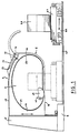
- Figure 1 is a side elevation of a wrapping apparatus according to the invention.
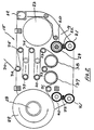
- Figure 2 is a diagrammatic longitudinal section through a shuttle, being a component of the apparatus of figure 1.
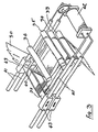
- Figure 3 is a diagrammatic perspective view of take-up accumulator means, being components of the shuttle of figure 2.
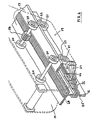
- Figure 4 is a diagrammatic perspective view of some internal parts of the shuttle of figure 2, showing more particularly its track wheels and electrical pick-up arrangements.
- the illustrated embodiment of the invention comprises a free standing support structure comprising a fabricated or cast metal column 5 extending rigidly upwardly from a floor mounting base 6. It supports a rigid loop structure comprising two spaced apart, co-directed cantilever beams 7 and 8 projecting from the column 5 and positioned one above the other in a common vertical plane and a gate portion 9 hinged at 10 one end to the free end of the upper beam 7 and extending, in its closed position, to the free end of the lower beam 8.
- the beams 7 and 8 and the gate portion 9 are preferably fabricated from steel plate and may comprise webs 16, inner edge flanges 17 and, in the case of beam 7, an outer edge flange 18.
- the loop structure as a whole may be raised or lowered as needed, by any conventional elevating mechanism associated with the column 5.
- it may be slideably mounted on the column and engaged by motor driven nuts threaded upon a screwed post within the column.
- the nuts may be fixed and the post rotatable, or an hydraulic or other thrustor may act directly on the loop structure.
- the gate portion 9 is a smoothly curved C shaped body and the junction between the bottom surface of the upper beam 7 and the upper surface of the lower beam 8 adjacent the column 5 is similarly smoothly curved.
- the beams 7 and 8 and the gate portion 9, when in the closed position, constitute an elongated rigid loop structure projecting from the column. That loop structure lies in a vertical plane with its long dimension substantially horizontal, it is spaced above the floor, preferably to an adjustable extent, and the opening 11 defined by it has a straight lower side and a smoothly curved upper side and ends.
- the axis of the gate portion hinge 10 extends transversely of the loop structure so that the gate portion 9 may be swung upwardly from a closed position (shown in full line in figure 1), wherein its two ends respectively register with the free ends of the beams 7 and 8, to an open position (shown in broken line), wherein it is substantially clear of the beams.
- the ends of the gate portion 9 and the free ends of the beam 7 and 8 may be furnished with tapered inter-engaging formations or the like to ensure an accurate register therebetween.
- a shuttle 15 is provided which may ride around the inner periphery of the loop structure on a guide track.
- the guide track may be seen as a T-sectioned rail formed by the inner flanges 17 and the adjacent margin of the webs 16 of the beams 7 and 8 and the gate portion 9.
- the shuttle 15 comprises two rigidly spaced apart side plates 19 on and between which are rotatably mounted two pairs of inner track wheels 20, two pairs of outer track wheels 21 and two pairs of side track wheels 22.
- Those wheels may be moulded plastics wheels mounted for free rolling, in the case of the inner and outer wheels, on axles extending from one side plate 19 to the other and, in the case of the side track wheels, on brackets attached to the respective side plates. It will be clear to the skilled reader that the track wheels as a whole retain the shuttle to the head flange of the T-sectioned guide track while permitting it to ride therealong.
- the motor 23 may be energised by way of wiper contacts on the shuttle contacting rigid electric supply conductors mounted on, and extending for the full lengths of, the inner margins of the webs 16.
- wiper contacts and conductors are conventional items that are commercially available. They comprise conductor rails housed deep within insulating channels 25 and coacting sets of shoes 26 adapted to enter the mouths of the channels to make sliding contact with the rails.
- the shoes 26 are resiliently mounted on insulated conducting arms 27 rigidly mounted on a shuttle side plate 19. Two sets of shoes 26 are provided in respect of each rail to maintain continuity of supply as the shuttle travels across the junctions between the gate portion 9 and the beams 7 and 8.
- the supply to the conductor rails on the gate portion 9 may be maintained by contact at the beam ends when the gate portion is in the closed position, but for preference the supply is maintained by flexible conductors spanning the hinge.
- the shuttle 15 further comprises a mandrel or other spool holder 28 for a roll 29 of pliable wrapping medium, for example stretch plastic wrapping film, from which film 30 may be drawn, six fixedly positioned training rollers 31 to 36 respectively, two pre-stretch rollers 37 and 38 respectively, and two yieldably positioned training rollers 39 and 40 respectively.
- pliable wrapping medium for example stretch plastic wrapping film
- pre-stretch rollers 37 and 38 cooperate with the training rolls 31, 32 and 33 to effect initial stretching of the film 5 as it leaves the roll 29. Their curved surfaces are conditioned in known manner to provide a considerable degree of friction between those surfaces and the film 30. Furthermore pre-stretch roller 38 runs at a higher speed than roller 37, so that the film 30 is necessarily stretched as it passes around the rollers. They also provide a brake on the film enabling it to be kept in tension by the article being wrapped.
- the rollers 39 and 40 are resiliently loaded away from the rollers 33, 34 and 35 by loading means comprising, in this instance, so called rodless pneumatic cylinders 41 that are each vented at one end and connected at the other end to a pressurised air reservoir 42.
- the cylinders 41 are also conventional proprietary items. Essentially each comprises an elongate cylinder with an internal piston and an external saddle 43, both of which are slidable longitudinally of the cylinder. The piston and saddle are kept in register by strong interacting permanent magnets respectively fixedly associated with them. This enables the rollers 39 and 40 to move to and fro with the saddles 43, as indicated by the arrows in figure 3, while maintaining a substantially constant tension in the variable quantity of the film 30 trained around them and the rollers 33, 34 and 35.
- the volume of the reservoir 42 is sufficient to ensure that the air pressure within the cylinders 41 does not vary greatly as the pistons therein move to and fro.
- the numbers and spacing of the rollers of the accumulator means may be different from that illustrated and the loading means may take other convenient forms, for example springs or a capstan drum driven through a constant torque, slipping clutch.
- a work piece support means is provided at a lower level than the loop structure. That support means may be fixed in position but preferably it is in the nature of a trolley 44 able to run on floor rails 45 to enable it to be loaded with the work piece, for example a coil 46 of steel strip, elsewhere, and then brought into position below the loop structure (as indicated in broken line in figure 1). If the support means are fixed in position, it is desirable for the loop structure to be movable horizontally. Thus, in the instance of apparatus along the lines of that illustrated, the column base 6 would be designed to run on rails corresponding to the rails 45.
- the work piece support means preferably have two power driven, spaced apart, horizontal rollers 47 for the support of the work piece 46.
- the gate portion 9 is moved to the open position, the coil 46 of metal strip or other annular article to be wrapped is then positioned on the work piece support rollers 47, and those means moved along the rails 45 so that the lower beam 8 extends through the bore of the coil 46, the gate portion 9 is then closed so that the shuttle track is linked with the work piece 46, that is to say a part of the endless track extends through the bore of the work piece 46.
- An end of film 30 may then be drawn from the shuttle 15 and taped or otherwise fixed to the work piece 46.
- the shuttle 15 is then set in motion to wrap a turn of film around the upper part of the work piece and the work piece support means rollers 47 are set going until successive overlapping turns of film cover the entire surface of the coil 46, including its inner bore surface.
- the invention may wrap annular articles as described above it is not limited to such use.
- the provision of a shuttle mounted spool holder travelling around an endless, gated track permits the ready positioning of many articles so that they are surrounded by the shuttle path and therefore able to be wrapped by the shuttle following that path.
- the work piece support means may be adapted for the support of non-annular work pieces.
- elongated articles may be passed continuously through the track loop by appropriate conveyors of known kind.
- the gate portion is not necessarily hingedly moved or swung between its open and closed position. It may be moved translationally or bodily from one position to the other. Such translational movement may be in the plane of the remainder of the loop structure or transversely thereof.
- the gate portion is effectively the top part of a more upright loop structure than that illustrated. It is opened by being lifted from the lower part of the structure and closed by being lowered onto the lower part.
- a loop structure similar to that illustrated is provided, except that only the top part of the structure is raised and lowered by elevator means associated with a column corresponding to column 5.
- the work piece support means may comprise a circular array of axially radiating conical rollers for the support of a work piece such as coil 46 lying on one end and its rotation about its then vertical axis.
Landscapes
- Engineering & Computer Science (AREA)
- Mechanical Engineering (AREA)
- Basic Packing Technique (AREA)
- Packaging Of Special Articles (AREA)
- Auxiliary Devices For And Details Of Packaging Control (AREA)
- Load-Engaging Elements For Cranes (AREA)
- Packages (AREA)
- Control And Other Processes For Unpacking Of Materials (AREA)
Applications Claiming Priority (4)
| Application Number | Priority Date | Filing Date | Title |
|---|---|---|---|
| AU9726/91 | 1991-11-27 | ||
| AUPK972691 | 1991-11-27 | ||
| AU1886/92 | 1992-04-13 | ||
| AUPL188692 | 1992-04-13 |
Publications (2)
| Publication Number | Publication Date |
|---|---|
| EP0544312A1 true EP0544312A1 (fr) | 1993-06-02 |
| EP0544312B1 EP0544312B1 (fr) | 1996-03-06 |
Family
ID=25644164
Family Applications (1)
| Application Number | Title | Priority Date | Filing Date |
|---|---|---|---|
| EP92120239A Expired - Lifetime EP0544312B1 (fr) | 1991-11-27 | 1992-11-26 | Dispositif pour envelopper des objets annulaires |
Country Status (15)
| Country | Link |
|---|---|
| US (1) | US5282347A (fr) |
| EP (1) | EP0544312B1 (fr) |
| JP (1) | JP2753671B2 (fr) |
| KR (1) | KR100238987B1 (fr) |
| CN (1) | CN1039109C (fr) |
| AT (1) | ATE134954T1 (fr) |
| BR (1) | BR9204578A (fr) |
| CA (1) | CA2083905C (fr) |
| DE (1) | DE69208828T2 (fr) |
| ES (1) | ES2084912T3 (fr) |
| IN (1) | IN179999B (fr) |
| MX (1) | MX9206873A (fr) |
| MY (1) | MY108281A (fr) |
| NZ (1) | NZ245225A (fr) |
| PH (1) | PH30322A (fr) |
Cited By (12)
| Publication number | Priority date | Publication date | Assignee | Title |
|---|---|---|---|---|
| WO1995012525A1 (fr) * | 1993-11-05 | 1995-05-11 | Bhp Steel (Awi) Pty. Ltd. | Dispositif et procede de ligature sur bobine |
| WO1996036535A1 (fr) * | 1995-04-28 | 1996-11-21 | Companhia Siderúrgica Nacional | Amelioration d'une emballeuse pour l'emballage de feuilles et de bobines d'aciers a course horizontale |
| EP0936141A1 (fr) | 1998-02-11 | 1999-08-18 | Oy M. Haloila Ab | Machine pour envelopper |
| EP1008522A1 (fr) * | 1998-12-11 | 2000-06-14 | Oy M. Haloila Ab | Dispositif d'enveloppement |
| WO2001042085A1 (fr) * | 1999-12-06 | 2001-06-14 | Luiz Henrique Araujo | Machine d'emballage de bobines |
| EP1172298A1 (fr) * | 1999-01-29 | 2002-01-16 | Kohan Kogyo Co. Ltd. | Dispositif d'emballage |
| US6446418B1 (en) | 1998-02-10 | 2002-09-10 | Illinois Tool Works, Inc. | Packaging device |
| EP1253083A1 (fr) * | 2001-04-19 | 2002-10-30 | ITW Limited | Dispositif pour régler la tension d' une bande |
| WO2003093111A1 (fr) * | 2002-04-30 | 2003-11-13 | Pesmel Oy | Enveloppeuse a piste circulaire et dispositif d'alimentation en film |
| EP1464579A2 (fr) * | 2003-02-25 | 2004-10-06 | Octomeca Oy | Machine à banderoler |
| WO2008085702A1 (fr) * | 2007-01-12 | 2008-07-17 | Illinois Tool Works Inc. | Système de changement de navette et procédé pour changer une navette |
| NL2012215C2 (nl) * | 2014-02-06 | 2015-08-10 | Bandall Benelux B V | Inrichting voor het rond een product aanbrengen van een band flexibel materiaal. |
Families Citing this family (37)
| Publication number | Priority date | Publication date | Assignee | Title |
|---|---|---|---|---|
| JP3807510B2 (ja) * | 1993-08-31 | 2006-08-09 | Jfeスチール株式会社 | 昇降機構付き往復走行台車を使用したコイル梱包ライン |
| AUPM388194A0 (en) * | 1994-02-14 | 1994-03-10 | John Lysaght (Australia) Limited | Wrapping apparatus with shuttle change |
| AU676117B1 (en) * | 1995-09-22 | 1997-02-27 | Itw Limited | Film stretching mechanism |
| US5775515A (en) * | 1996-05-06 | 1998-07-07 | Chadwick Engineering Limited | Method and apparatus for wrapping coils, and the wrapped product |
| FI101281B1 (fi) * | 1996-08-23 | 1998-05-29 | Haloila M Oy Ab | Laite käärintäkalvon kietomiseksi pakattavan tavaran ympärille |
| US5850726A (en) * | 1996-11-12 | 1998-12-22 | Lantech, Inc. | Wrapping apparatus and method |
| US6032436A (en) * | 1998-01-29 | 2000-03-07 | Herr-Voss Corporation | Wrapping apparatus and method |
| US6324820B1 (en) | 2000-03-23 | 2001-12-04 | Intergrated Industrial Systems, Inc. | Spool transfer coil wrapping machine |
| JP4546618B2 (ja) * | 2000-06-22 | 2010-09-15 | 新日本製鐵株式会社 | 梱包装置の運転方法 |
| US6729106B2 (en) | 2001-06-15 | 2004-05-04 | Robert B. Wiley | Orbital pallet wrapping machine and method |
| FI114307B (fi) * | 2002-04-30 | 2004-09-30 | Pesmel Oy | Kalvonjakelulaitteisto ja automaattinen käärintälaitteisto |
| US6688076B1 (en) * | 2002-05-30 | 2004-02-10 | Victor M. Rivera, Jr. | Apparatus for wrapping articles in film material |
| US6966163B2 (en) * | 2002-10-11 | 2005-11-22 | Chs Acquisition Corp. | Method for banding product and apparatus therefor |
| DE102004023532A1 (de) * | 2004-03-15 | 2005-10-06 | H. Böhl GmbH | Verfahren zum Umwickeln eines lang- oder Rundteils, beispielsweise eines Stahlteils |
| FI20060457A0 (fi) * | 2006-05-10 | 2006-05-10 | Juha-Matti Laensikallio | Käärintälaite |
| US8334045B2 (en) * | 2008-04-29 | 2012-12-18 | Newfrey Llc | Wrapping tape for a cable harness |
| US8210483B2 (en) * | 2008-04-29 | 2012-07-03 | Newfrey Llc | Fastening element for a cable harness |
| US8146491B2 (en) * | 2008-04-29 | 2012-04-03 | Newfrey Llc | Apparatus and method for automatically, circumferentially wrapping a cable harness |
| US8650836B2 (en) * | 2009-04-14 | 2014-02-18 | Illinois Tool Works Inc. | Film-tail sealing system and method for wrapping apparatus |
| CN101804872A (zh) * | 2010-03-09 | 2010-08-18 | 鞍山市弘鑫包装材料有限公司 | 钢卷包装用自动薄膜缠绕机 |
| US20130055678A1 (en) * | 2010-03-15 | 2013-03-07 | Kna Corporation Oy | Coil Packaging System |
| CA2764476A1 (fr) * | 2011-01-14 | 2012-07-14 | Groupe Anderson Inc. | Machine d'emballage et enveloppeuse en ligne ainsi equipee |
| ES2583783T3 (es) * | 2011-08-16 | 2016-09-22 | Aetna Group S.P.A. | Sistema para mover unidades operativas de una máquina envolvedora y máquina envolvedora |
| CN102367076B (zh) | 2011-10-02 | 2013-11-06 | 上海宏曲电子科技有限公司 | 管状材料包装的挂式并推型排队装置 |
| EP2876068B1 (fr) * | 2013-11-26 | 2017-10-18 | KNA Corporation OY | Appareil, procédé et système permettant d'emballer un matériau d'emballage, dispositif d'emballage et unité de commande |
| EP3481729B1 (fr) * | 2016-07-05 | 2021-04-14 | Taylor-Winfield Technologies, Inc. | Machine de cerclage robotise et procede |
| CN106945860A (zh) * | 2017-05-19 | 2017-07-14 | 上海景林包装机械有限公司 | 一种用于环状物体包装的小车行走轨道装置 |
| US10854035B2 (en) * | 2018-03-07 | 2020-12-01 | The Hillman Group, Inc. | Automated packaging system for a self-service custom-fabrication kiosk |
| USD869527S1 (en) * | 2018-06-11 | 2019-12-10 | Baron Buehring | Side panel for high capacity dispensing unit |
| USD868859S1 (en) * | 2018-06-11 | 2019-12-03 | Baron Buehring | Side panel for high capacity dispensing unit |
| USD868858S1 (en) * | 2018-06-11 | 2019-12-03 | Baron Buehring | Side panel for high capacity dispensing unit |
| USD873317S1 (en) * | 2018-06-11 | 2020-01-21 | Baron Buehring | Side panel for high capacity dispensing unit |
| USD868860S1 (en) * | 2018-06-11 | 2019-12-03 | Baron Buehring | Side panel for high capacity dispensing unit |
| CN110077671A (zh) * | 2019-04-30 | 2019-08-02 | 哈工大机器人智能制造有限公司 | 筒状产品外包装捆扎机构及方法 |
| CN112938068A (zh) * | 2021-03-09 | 2021-06-11 | 北京首钢国际工程技术有限公司 | 一种覆膜机机头 |
| CN114084399B (zh) * | 2021-12-02 | 2023-02-14 | 山东银宝轮胎集团有限公司 | 一种轮胎缠膜机 |
| CN116741531B (zh) * | 2023-08-14 | 2023-11-03 | 浙江炬源物联科技有限公司 | 一种互感器绝缘聚酯薄膜梭子自动缠绕设备及其缠绕工艺 |
Citations (3)
| Publication number | Priority date | Publication date | Assignee | Title |
|---|---|---|---|---|
| DE1244045B (de) * | 1964-04-10 | 1967-07-06 | Hans Boehl Maschinenfabrik | Einwickelmaschine fuer ringfoermige Gueter |
| FR2057524A5 (fr) * | 1969-08-25 | 1971-05-21 | Ural Z Tyazhelogo | |
| DE2256708A1 (de) * | 1972-11-18 | 1974-05-22 | Transporttechnik Gmbh | Umwicklungsmaschine |
Family Cites Families (16)
| Publication number | Priority date | Publication date | Assignee | Title |
|---|---|---|---|---|
| US3116032A (en) * | 1961-06-28 | 1963-12-31 | Package Machinery Co | Web feeding system |
| NL6600102A (fr) * | 1966-01-05 | 1967-07-06 | ||
| US3348787A (en) * | 1966-05-20 | 1967-10-24 | Nu Roll Corp | Drive and drive control for supply rolls |
| JPS4887997A (fr) * | 1972-02-25 | 1973-11-19 | ||
| JPS50150597A (fr) * | 1974-05-27 | 1975-12-03 | ||
| SU761374A1 (ru) * | 1978-07-10 | 1980-09-07 | Od Staleprokatnyj Z Im Dzerzhi | Устройство для упаковки кольцеобразных изделий 1 |
| US4317322A (en) * | 1980-05-20 | 1982-03-02 | Lantech, Inc. | Rotatable film wrapping apparatus with wrap carrying mechanism |
| EP0044627B1 (fr) * | 1980-06-25 | 1986-04-09 | Encomech Product Development Limited | Dispositif pour l'emballage d'un rouleau de tôle ou de bande métallique |
| GB2079730B (en) * | 1980-07-10 | 1984-02-15 | Baker Perkins Holdings Ltd | Tensioning web by clamping side faces of wound web reel |
| AU7496981A (en) * | 1980-09-08 | 1982-03-18 | E.G. Rowe Pty Ltd | Orbital wrapper |
| SU982977A1 (ru) * | 1981-07-22 | 1982-12-23 | Одесское Сталепрокатное Производственное Объединение Им.Дзержинского | Устройство дл упаковки мотков проволоки |
| JPS58183414A (ja) * | 1982-04-20 | 1983-10-26 | ストラパック株式会社 | 梱包装置 |
| US4761934A (en) * | 1987-02-27 | 1988-08-09 | Lantech | Parallel belted clamp |
| SU1465347A1 (ru) * | 1987-04-13 | 1989-03-15 | Магнитогорский Метизно-Металлургический Завод | Устройство дл упаковывани кольцеобразных изделий |
| US4829753A (en) * | 1988-01-15 | 1989-05-16 | Bricmont Francis H | Apparatus for wrapping overlapping laps of strip material over a cylindrical object having an axial opening therein |
| FR2639904B1 (fr) * | 1988-12-01 | 1991-07-05 | Marion Louis | Procede et moyens d'ensachage de plusieurs compresses, ainsi que le sachet obtenu |
-
1992
- 1992-09-09 US US07/942,067 patent/US5282347A/en not_active Expired - Lifetime
- 1992-10-07 MY MYPI92001811A patent/MY108281A/en unknown
- 1992-10-09 PH PH45077A patent/PH30322A/en unknown
- 1992-11-23 NZ NZ245225A patent/NZ245225A/xx not_active IP Right Cessation
- 1992-11-24 IN IN856CA1992D patent/IN179999B/en unknown
- 1992-11-24 JP JP4338015A patent/JP2753671B2/ja not_active Expired - Lifetime
- 1992-11-26 CA CA002083905A patent/CA2083905C/fr not_active Expired - Lifetime
- 1992-11-26 BR BR9204578A patent/BR9204578A/pt not_active IP Right Cessation
- 1992-11-26 ES ES92120239T patent/ES2084912T3/es not_active Expired - Lifetime
- 1992-11-26 DE DE69208828T patent/DE69208828T2/de not_active Expired - Lifetime
- 1992-11-26 AT AT92120239T patent/ATE134954T1/de not_active IP Right Cessation
- 1992-11-26 EP EP92120239A patent/EP0544312B1/fr not_active Expired - Lifetime
- 1992-11-27 KR KR1019920022673A patent/KR100238987B1/ko not_active IP Right Cessation
- 1992-11-27 MX MX9206873A patent/MX9206873A/es unknown
- 1992-11-27 CN CN92112860A patent/CN1039109C/zh not_active Expired - Lifetime
Patent Citations (3)
| Publication number | Priority date | Publication date | Assignee | Title |
|---|---|---|---|---|
| DE1244045B (de) * | 1964-04-10 | 1967-07-06 | Hans Boehl Maschinenfabrik | Einwickelmaschine fuer ringfoermige Gueter |
| FR2057524A5 (fr) * | 1969-08-25 | 1971-05-21 | Ural Z Tyazhelogo | |
| DE2256708A1 (de) * | 1972-11-18 | 1974-05-22 | Transporttechnik Gmbh | Umwicklungsmaschine |
Cited By (26)
| Publication number | Priority date | Publication date | Assignee | Title |
|---|---|---|---|---|
| WO1995012525A1 (fr) * | 1993-11-05 | 1995-05-11 | Bhp Steel (Awi) Pty. Ltd. | Dispositif et procede de ligature sur bobine |
| WO1996036535A1 (fr) * | 1995-04-28 | 1996-11-21 | Companhia Siderúrgica Nacional | Amelioration d'une emballeuse pour l'emballage de feuilles et de bobines d'aciers a course horizontale |
| EP1813532A1 (fr) * | 1998-02-10 | 2007-08-01 | Illinois Tool Works Inc. | Dispositif d'emballage |
| EP1520786A1 (fr) * | 1998-02-10 | 2005-04-06 | Illinois Tool Works Inc. | Moyen d' enveloppement rotatif pour un dispositif d' emballage. |
| US6446418B1 (en) | 1998-02-10 | 2002-09-10 | Illinois Tool Works, Inc. | Packaging device |
| CN1106982C (zh) * | 1998-02-11 | 2003-04-30 | 厄于·M·哈洛拉Ab有限公司 | 打包机 |
| EP0936141A1 (fr) | 1998-02-11 | 1999-08-18 | Oy M. Haloila Ab | Machine pour envelopper |
| US6305145B2 (en) | 1998-02-11 | 2001-10-23 | Oy M. Haloila Ab | Wrapping apparatus |
| EP1008522A1 (fr) * | 1998-12-11 | 2000-06-14 | Oy M. Haloila Ab | Dispositif d'enveloppement |
| CN1106979C (zh) * | 1998-12-11 | 2003-04-30 | 厄于·M·哈洛拉Ab有限公司 | 包扎机 |
| EP1172298A4 (fr) * | 1999-01-29 | 2003-09-17 | Kohan Kogyo Co Ltd | Dispositif d'emballage |
| EP1172298A1 (fr) * | 1999-01-29 | 2002-01-16 | Kohan Kogyo Co. Ltd. | Dispositif d'emballage |
| WO2001042085A1 (fr) * | 1999-12-06 | 2001-06-14 | Luiz Henrique Araujo | Machine d'emballage de bobines |
| US6520445B2 (en) | 1999-12-06 | 2003-02-18 | Luiz Henrique Araujo | Coil wrapping machine |
| EP1253083A1 (fr) * | 2001-04-19 | 2002-10-30 | ITW Limited | Dispositif pour régler la tension d' une bande |
| US6775961B2 (en) | 2001-04-19 | 2004-08-17 | Itw Ltd | Web tensioning device |
| CN1328116C (zh) * | 2002-04-30 | 2007-07-25 | 佩斯梅尔有限公司 | 具有圆形轨道装置和薄膜输送装置的包装装置 |
| WO2003093111A1 (fr) * | 2002-04-30 | 2003-11-13 | Pesmel Oy | Enveloppeuse a piste circulaire et dispositif d'alimentation en film |
| EP1464579A3 (fr) * | 2003-02-25 | 2005-06-15 | Octomeca Oy | Machine à banderoler |
| EP1464579A2 (fr) * | 2003-02-25 | 2004-10-06 | Octomeca Oy | Machine à banderoler |
| WO2008085702A1 (fr) * | 2007-01-12 | 2008-07-17 | Illinois Tool Works Inc. | Système de changement de navette et procédé pour changer une navette |
| CN101553402B (zh) * | 2007-01-12 | 2011-05-18 | 伊利诺斯工具制品有限公司 | 用于更换梭子的梭子更换系统和方法 |
| US8037661B2 (en) | 2007-01-12 | 2011-10-18 | Illinois Tool Works Inc. | Shuttle change system and method for wrapping apparatus |
| KR101531962B1 (ko) * | 2007-01-12 | 2015-06-26 | 시그노드 인터내셔널 아이피 홀딩스 엘엘씨 | 셔틀을 교환하기 위한 셔틀 교환 시스템 및 방법 |
| NL2012215C2 (nl) * | 2014-02-06 | 2015-08-10 | Bandall Benelux B V | Inrichting voor het rond een product aanbrengen van een band flexibel materiaal. |
| WO2015119499A1 (fr) * | 2014-02-06 | 2015-08-13 | Bandall Benelux B.V. | Appareil pour fournir une bande de matériau souple autour d'un produit |
Also Published As
| Publication number | Publication date |
|---|---|
| CA2083905A1 (fr) | 1993-05-28 |
| NZ245225A (en) | 1994-08-26 |
| JPH05294314A (ja) | 1993-11-09 |
| DE69208828D1 (de) | 1996-04-11 |
| BR9204578A (pt) | 1993-06-01 |
| CN1078701A (zh) | 1993-11-24 |
| DE69208828T2 (de) | 1996-10-02 |
| CN1039109C (zh) | 1998-07-15 |
| US5282347A (en) | 1994-02-01 |
| ATE134954T1 (de) | 1996-03-15 |
| MY108281A (en) | 1996-09-30 |
| ES2084912T3 (es) | 1996-05-16 |
| JP2753671B2 (ja) | 1998-05-20 |
| CA2083905C (fr) | 2003-04-15 |
| IN179999B (fr) | 1998-01-03 |
| EP0544312B1 (fr) | 1996-03-06 |
| KR100238987B1 (ko) | 2000-03-02 |
| KR930009864A (ko) | 1993-06-21 |
| MX9206873A (es) | 1993-05-01 |
| PH30322A (en) | 1997-03-06 |
Similar Documents
| Publication | Publication Date | Title |
|---|---|---|
| EP0544312B1 (fr) | Dispositif pour envelopper des objets annulaires | |
| US5203139A (en) | Apparatus and method for winding and wrapping rolls of web material | |
| US20090211200A1 (en) | Apparatus and method for stretch wrapping of a plurality of tubes | |
| US4102512A (en) | System for forming sheet material into spiral rolls | |
| JPS63235249A (ja) | 平らな形成物を連続的に巻き取って巻取物とし、または巻取物からこれを連続的に繰出す装置 | |
| US3599851A (en) | Hydrodynamic turnover mechanisms | |
| US4285630A (en) | Method of automatically transferring a plurality of objects between two different supporting surfaces | |
| AU653255B2 (en) | Wrapping apparatus | |
| US3515327A (en) | Apparatus for storing a variable length of strip | |
| MXPA02003864A (es) | Dispositivo para aplicar tension a una membrana. | |
| JPH04371441A (ja) | 帯状部材の巻取装置 | |
| CN117466040A (zh) | 一种应用卧式储料装置的涂布机及其工作方式 | |
| US4409777A (en) | Web threading apparatus | |
| US5186408A (en) | Machine for winding elongated strips on an axle mounted core | |
| US6343763B1 (en) | Transferring winding from a filled cylindrical package of an elongate material to an empty core | |
| FI90504C (fi) | Nauhanohjain kelauslaitteita varten | |
| JPS598572B2 (ja) | 車両用の積卸装置 | |
| US5899657A (en) | Automated mechanical storage facility | |
| FR2757141B1 (fr) | Machine d'enroulement d'un element plat continu pour former des bobines | |
| US4410121A (en) | Spiral coil strip accumulator and method | |
| CN211281582U (zh) | 一种钢卷绕膜机 | |
| US3064918A (en) | Loose coiling installation | |
| JP2002166906A (ja) | 包装装置およびこれに用いるハンドリング装置 | |
| US4456189A (en) | Controlled expansion strip accumulator | |
| JPH0368808B2 (fr) |
Legal Events
| Date | Code | Title | Description |
|---|---|---|---|
| PUAI | Public reference made under article 153(3) epc to a published international application that has entered the european phase |
Free format text: ORIGINAL CODE: 0009012 |
|
| AK | Designated contracting states |
Kind code of ref document: A1 Designated state(s): AT BE CH DE DK ES FR GB GR IE IT LI LU MC NL PT SE |
|
| 17P | Request for examination filed |
Effective date: 19931014 |
|
| 17Q | First examination report despatched |
Effective date: 19940808 |
|
| RAP1 | Party data changed (applicant data changed or rights of an application transferred) |
Owner name: BHP STEEL (JLA) PTY LTD Owner name: K.C. METAL PRODUCTS PROPRIETARY LIMITED |
|
| GRAH | Despatch of communication of intention to grant a patent |
Free format text: ORIGINAL CODE: EPIDOS IGRA |
|
| GRAA | (expected) grant |
Free format text: ORIGINAL CODE: 0009210 |
|
| AK | Designated contracting states |
Kind code of ref document: B1 Designated state(s): AT BE CH DE DK ES FR GB GR IE IT LI LU MC NL PT SE |
|
| PG25 | Lapsed in a contracting state [announced via postgrant information from national office to epo] |
Ref country code: GR Free format text: LAPSE BECAUSE OF FAILURE TO SUBMIT A TRANSLATION OF THE DESCRIPTION OR TO PAY THE FEE WITHIN THE PRESCRIBED TIME-LIMIT Effective date: 19960306 Ref country code: AT Effective date: 19960306 Ref country code: DK Effective date: 19960306 |
|
| REF | Corresponds to: |
Ref document number: 134954 Country of ref document: AT Date of ref document: 19960315 Kind code of ref document: T |
|
| REG | Reference to a national code |
Ref country code: IE Ref legal event code: FG4D Free format text: 67461 |
|
| REF | Corresponds to: |
Ref document number: 69208828 Country of ref document: DE Date of ref document: 19960411 |
|
| REG | Reference to a national code |
Ref country code: ES Ref legal event code: FG2A Ref document number: 2084912 Country of ref document: ES Kind code of ref document: T3 |
|
| ITF | It: translation for a ep patent filed | ||
| PG25 | Lapsed in a contracting state [announced via postgrant information from national office to epo] |
Ref country code: PT Effective date: 19960607 |
|
| ET | Fr: translation filed | ||
| PG25 | Lapsed in a contracting state [announced via postgrant information from national office to epo] |
Ref country code: LU Free format text: LAPSE BECAUSE OF NON-PAYMENT OF DUE FEES Effective date: 19961130 |
|
| PLBQ | Unpublished change to opponent data |
Free format text: ORIGINAL CODE: EPIDOS OPPO |
|
| PLBI | Opposition filed |
Free format text: ORIGINAL CODE: 0009260 |
|
| PLBF | Reply of patent proprietor to notice(s) of opposition |
Free format text: ORIGINAL CODE: EPIDOS OBSO |
|
| 26 | Opposition filed |
Opponent name: ILLINOIS TOOL WORKS, INC. Effective date: 19961205 |
|
| NLR1 | Nl: opposition has been filed with the epo |
Opponent name: ILLINOIS TOOL WORKS, INC. |
|
| PLBF | Reply of patent proprietor to notice(s) of opposition |
Free format text: ORIGINAL CODE: EPIDOS OBSO |
|
| PG25 | Lapsed in a contracting state [announced via postgrant information from national office to epo] |
Ref country code: MC Effective date: 19970531 |
|
| PLBF | Reply of patent proprietor to notice(s) of opposition |
Free format text: ORIGINAL CODE: EPIDOS OBSO |
|
| PLBL | Opposition procedure terminated |
Free format text: ORIGINAL CODE: EPIDOS OPPC |
|
| PLBM | Termination of opposition procedure: date of legal effect published |
Free format text: ORIGINAL CODE: 0009276 |
|
| STAA | Information on the status of an ep patent application or granted ep patent |
Free format text: STATUS: OPPOSITION PROCEDURE CLOSED |
|
| 27C | Opposition proceedings terminated |
Effective date: 19971121 |
|
| NLR2 | Nl: decision of opposition | ||
| REG | Reference to a national code |
Ref country code: CH Ref legal event code: PUE Owner name: BHP STEEL (JLA) PTY LTD;K.C. METAL PRODUCTS PROPRI Ref country code: CH Ref legal event code: NV Representative=s name: E. BLUM & CO. PATENTANWAELTE |
|
| REG | Reference to a national code |
Ref country code: GB Ref legal event code: 732E |
|
| REG | Reference to a national code |
Ref country code: ES Ref legal event code: PC2A |
|
| NLS | Nl: assignments of ep-patents |
Owner name: K.C. METAL PRODUCTS PROPRIETARY LIMITED |
|
| BECA | Be: change of holder's address |
Free format text: 20010612 *K.C. METAL PRODUCTS PROPRIETARYLTD:24 COLLINS ROAD,DROMANA VICTORIA 3936 |
|
| REG | Reference to a national code |
Ref country code: GB Ref legal event code: IF02 |
|
| REG | Reference to a national code |
Ref country code: FR Ref legal event code: TP |
|
| BECA | Be: change of holder's address |
Owner name: *ITW LTDADMIRAL HOUSE, ST. LEONARDS ROAD, WINDSOR, Effective date: 20031127 |
|
| REG | Reference to a national code |
Ref country code: CH Ref legal event code: PUE Owner name: ITW LIMITED Free format text: K.C. METAL PRODUCTS PROPRIETARY LIMITED#24 COLLINS ROAD#DROMANA, VICTORIA 3936 (AU) -TRANSFER TO- ITW LIMITED#ADMIRAL HOUSE, ST. LEONARD'S ROAD#WINDSOR, BERKSHIRE SL4 3BL (GB) |
|
| REG | Reference to a national code |
Ref country code: GB Ref legal event code: 732E |
|
| REG | Reference to a national code |
Ref country code: ES Ref legal event code: PC2A |
|
| NLS | Nl: assignments of ep-patents |
Owner name: ITW LIMITED |
|
| REG | Reference to a national code |
Ref country code: FR Ref legal event code: TP |
|
| PGFP | Annual fee paid to national office [announced via postgrant information from national office to epo] |
Ref country code: NL Payment date: 20041029 Year of fee payment: 13 |
|
| PGFP | Annual fee paid to national office [announced via postgrant information from national office to epo] |
Ref country code: IE Payment date: 20041130 Year of fee payment: 13 |
|
| PGFP | Annual fee paid to national office [announced via postgrant information from national office to epo] |
Ref country code: BE Payment date: 20041216 Year of fee payment: 13 |
|
| PG25 | Lapsed in a contracting state [announced via postgrant information from national office to epo] |
Ref country code: IE Free format text: LAPSE BECAUSE OF NON-PAYMENT OF DUE FEES Effective date: 20051128 |
|
| PG25 | Lapsed in a contracting state [announced via postgrant information from national office to epo] |
Ref country code: BE Free format text: LAPSE BECAUSE OF NON-PAYMENT OF DUE FEES Effective date: 20051130 |
|
| PG25 | Lapsed in a contracting state [announced via postgrant information from national office to epo] |
Ref country code: NL Free format text: LAPSE BECAUSE OF NON-PAYMENT OF DUE FEES Effective date: 20060601 |
|
| NLV4 | Nl: lapsed or anulled due to non-payment of the annual fee |
Effective date: 20060601 |
|
| REG | Reference to a national code |
Ref country code: IE Ref legal event code: MM4A |
|
| REG | Reference to a national code |
Ref country code: CH Ref legal event code: PFA Owner name: ITW LIMITED Free format text: ITW LIMITED#ADMIRAL HOUSE, ST. LEONARD'S ROAD#WINDSOR, BERKSHIRE SL4 3BL (GB) -TRANSFER TO- ITW LIMITED#ADMIRAL HOUSE, ST. LEONARD'S ROAD#WINDSOR, BERKSHIRE SL4 3BL (GB) |
|
| BERE | Be: lapsed |
Owner name: *ITW LTD Effective date: 20051130 |
|
| PGFP | Annual fee paid to national office [announced via postgrant information from national office to epo] |
Ref country code: CH Payment date: 20081229 Year of fee payment: 17 |
|
| PGFP | Annual fee paid to national office [announced via postgrant information from national office to epo] |
Ref country code: ES Payment date: 20081226 Year of fee payment: 17 |
|
| REG | Reference to a national code |
Ref country code: CH Ref legal event code: PL |
|
| PG25 | Lapsed in a contracting state [announced via postgrant information from national office to epo] |
Ref country code: LI Free format text: LAPSE BECAUSE OF NON-PAYMENT OF DUE FEES Effective date: 20091130 Ref country code: CH Free format text: LAPSE BECAUSE OF NON-PAYMENT OF DUE FEES Effective date: 20091130 |
|
| PGFP | Annual fee paid to national office [announced via postgrant information from national office to epo] |
Ref country code: DE Payment date: 20101126 Year of fee payment: 19 |
|
| REG | Reference to a national code |
Ref country code: ES Ref legal event code: FD2A Effective date: 20110310 |
|
| PGFP | Annual fee paid to national office [announced via postgrant information from national office to epo] |
Ref country code: GB Payment date: 20101124 Year of fee payment: 19 Ref country code: IT Payment date: 20101124 Year of fee payment: 19 |
|
| PG25 | Lapsed in a contracting state [announced via postgrant information from national office to epo] |
Ref country code: ES Free format text: LAPSE BECAUSE OF NON-PAYMENT OF DUE FEES Effective date: 20110309 |
|
| PG25 | Lapsed in a contracting state [announced via postgrant information from national office to epo] |
Ref country code: ES Free format text: LAPSE BECAUSE OF NON-PAYMENT OF DUE FEES Effective date: 20091127 |
|
| PGFP | Annual fee paid to national office [announced via postgrant information from national office to epo] |
Ref country code: SE Payment date: 20111125 Year of fee payment: 20 Ref country code: FR Payment date: 20111128 Year of fee payment: 20 |
|
| REG | Reference to a national code |
Ref country code: DE Ref legal event code: R071 Ref document number: 69208828 Country of ref document: DE |
|
| REG | Reference to a national code |
Ref country code: DE Ref legal event code: R071 Ref document number: 69208828 Country of ref document: DE |
|
| REG | Reference to a national code |
Ref country code: GB Ref legal event code: PE20 Expiry date: 20121125 |
|
| REG | Reference to a national code |
Ref country code: SE Ref legal event code: EUG |
|
| PG25 | Lapsed in a contracting state [announced via postgrant information from national office to epo] |
Ref country code: GB Free format text: LAPSE BECAUSE OF EXPIRATION OF PROTECTION Effective date: 20121125 |