EP0543513B2 - Dispositif opto-électronique de lecture d'une échelle graduée - Google Patents
Dispositif opto-électronique de lecture d'une échelle graduée Download PDFInfo
- Publication number
- EP0543513B2 EP0543513B2 EP92309807A EP92309807A EP0543513B2 EP 0543513 B2 EP0543513 B2 EP 0543513B2 EP 92309807 A EP92309807 A EP 92309807A EP 92309807 A EP92309807 A EP 92309807A EP 0543513 B2 EP0543513 B2 EP 0543513B2
- Authority
- EP
- European Patent Office
- Prior art keywords
- elements
- sets
- pitch
- scale
- light pattern
- Prior art date
- Legal status (The legal status is an assumption and is not a legal conclusion. Google has not performed a legal analysis and makes no representation as to the accuracy of the status listed.)
- Expired - Lifetime
Links
- 230000005693 optoelectronics Effects 0.000 title claims description 5
- 230000000737 periodic effect Effects 0.000 claims description 20
- 125000004122 cyclic group Chemical group 0.000 claims 1
- 239000011295 pitch Substances 0.000 description 15
- 238000011109 contamination Methods 0.000 description 6
- 230000003287 optical effect Effects 0.000 description 6
- 230000010363 phase shift Effects 0.000 description 6
- 238000006073 displacement reaction Methods 0.000 description 5
- 239000000758 substrate Substances 0.000 description 5
- 238000003491 array Methods 0.000 description 4
- 239000004065 semiconductor Substances 0.000 description 4
- 238000010586 diagram Methods 0.000 description 3
- 238000000034 method Methods 0.000 description 3
- 238000010276 construction Methods 0.000 description 2
- 239000000463 material Substances 0.000 description 2
- 238000005259 measurement Methods 0.000 description 2
- 238000001465 metallisation Methods 0.000 description 2
- 239000000523 sample Substances 0.000 description 2
- JBRZTFJDHDCESZ-UHFFFAOYSA-N AsGa Chemical compound [As]#[Ga] JBRZTFJDHDCESZ-UHFFFAOYSA-N 0.000 description 1
- 229910001218 Gallium arsenide Inorganic materials 0.000 description 1
- XUIMIQQOPSSXEZ-UHFFFAOYSA-N Silicon Chemical compound [Si] XUIMIQQOPSSXEZ-UHFFFAOYSA-N 0.000 description 1
- 238000001514 detection method Methods 0.000 description 1
- 230000000694 effects Effects 0.000 description 1
- 238000009416 shuttering Methods 0.000 description 1
- 229910052710 silicon Inorganic materials 0.000 description 1
- 239000010703 silicon Substances 0.000 description 1
- 238000006467 substitution reaction Methods 0.000 description 1
Images

Classifications
-
- G—PHYSICS
- G01—MEASURING; TESTING
- G01D—MEASURING NOT SPECIALLY ADAPTED FOR A SPECIFIC VARIABLE; ARRANGEMENTS FOR MEASURING TWO OR MORE VARIABLES NOT COVERED IN A SINGLE OTHER SUBCLASS; TARIFF METERING APPARATUS; MEASURING OR TESTING NOT OTHERWISE PROVIDED FOR
- G01D5/00—Mechanical means for transferring the output of a sensing member; Means for converting the output of a sensing member to another variable where the form or nature of the sensing member does not constrain the means for converting; Transducers not specially adapted for a specific variable
- G01D5/26—Mechanical means for transferring the output of a sensing member; Means for converting the output of a sensing member to another variable where the form or nature of the sensing member does not constrain the means for converting; Transducers not specially adapted for a specific variable characterised by optical transfer means, i.e. using infrared, visible, or ultraviolet light
- G01D5/32—Mechanical means for transferring the output of a sensing member; Means for converting the output of a sensing member to another variable where the form or nature of the sensing member does not constrain the means for converting; Transducers not specially adapted for a specific variable characterised by optical transfer means, i.e. using infrared, visible, or ultraviolet light with attenuation or whole or partial obturation of beams of light
- G01D5/34—Mechanical means for transferring the output of a sensing member; Means for converting the output of a sensing member to another variable where the form or nature of the sensing member does not constrain the means for converting; Transducers not specially adapted for a specific variable characterised by optical transfer means, i.e. using infrared, visible, or ultraviolet light with attenuation or whole or partial obturation of beams of light the beams of light being detected by photocells
- G01D5/347—Mechanical means for transferring the output of a sensing member; Means for converting the output of a sensing member to another variable where the form or nature of the sensing member does not constrain the means for converting; Transducers not specially adapted for a specific variable characterised by optical transfer means, i.e. using infrared, visible, or ultraviolet light with attenuation or whole or partial obturation of beams of light the beams of light being detected by photocells using displacement encoding scales
- G01D5/34707—Scales; Discs, e.g. fixation, fabrication, compensation
- G01D5/34715—Scale reading or illumination devices
Definitions
- the present invention relates to an opto-electronic scale reading apparatus used, for example, to determine the magnitude and direction of movement of one member relative to another.
- Such an apparatus is typically used on coordinate positioning machines such as machine tools or coordinate measuring machines.
- GB Patent No. 1,504,691 It is known from GB Patent No. 1,504,691 to provide a reflective scale which is scanned by a readhead having an index grating and an analyser grating.
- the readhead illuminates the scale via the index grating, and a periodic light pattern in the form interference fringes is formed at the analyser grating as a result.
- the fringes move across the analyser grating creating, at a given point on the analyser, a light intensity modulation.
- the analyser grating may be positioned so that its lines extend fractionally obliquely to the interference fringes; this results in the generation of moiré fringes.
- Four photo-detectors behind the analyser grating are offset with respect to a single moiré fringe so that four phase-shifted cyclically varying electrical signals are produced, from which the magnitude and direction of said relative movement may be determined.
- GB 1,231,029 proposes, in substitution of the analyser grating, a detector array comprising a plurality of photosensitive elements which combine the functions of the analyser grating and the photo-detectors. In order to provide phase-shifted detection signals, two or more of such detector arrays are required.
- the present invention provides opto-electronic scale reading apparatus according to claim 1.
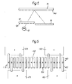
- the mechanism disclosed in EP 207121 may be used to generate the periodic light pattern; alternatively, the mechanism shown in GB 1,504,691 may be used.
- the pitch of the light pattern generated is equal to, or less than (e.g. 1 ⁇ 2 the pitch) the pitch of the scale lines.
- the pitch of the scale lines will be between 20 and 40 microns.
- the light intensity distribution in the image plane is illustrated in a graph in Fig 2a, and has a substantially sinusoidal shape characterised by peaks 18, corresponding to positions upon the analyser at which a high intensity of light is incident, and troughs 20, corresponding to positions on the analyser at which a low intensity of light is incident.
- the period, or pitch of the periodic light pattern is denoted in Fig 2 as the distance P.
- Fig 2b illustrates the analyser 16 (to the same scale as the graph).
- the analyser 16 comprises a semi-conductor substrate 22 having, on its surface, an array of elongate photo-sensitive elements 24 spaced-apart in the x direction.
- Each of the elements 24 is electrically insulated from an adjacent element, by an insulating guard diode 26.
- the elements 24 are divided into three sets A,B,C and are positioned across the array in an interleaved repeating pattern A,B,C, A,B,C; the elements of each set are electrically connected.
- the spacing between elements 24 of the set A from elements 24 of the set B, and the spacing between elements 24 of the set B from elements 24 of the set C is equal to 11 ⁇ 4 pitches P of the periodic light pattern; the spacing between elements 24 of the set A from elements 24 of the set C is equal to 11 ⁇ 2 pitches P of the periodic light pattern.
- Elements 24 of a given set are therefore spaced from adjacent elements 24 of that set by 4 pitches P of the periodic light pattern (i.e. 11 ⁇ 4+11 ⁇ 4+11 ⁇ 2).
- the periodic light pattern moves across the surface of the analyser 16. Because all elements 24 of a given set are spaced from each other by an integer multiple of the pitch P of the periodic light pattern, the same intensity of light will be incident upon all the elements 24 of the given set at any given moment in time. Further, the spacing of 11 ⁇ 4 pitches P between elements 24 of the sets A and B, and elements 24 of the sets B and C corresponds to a phase shift of 360° + 90°. Therefore, as the light pattern moves across the surface of the analyser 16 the electrical outputs of the sets A and B, and B and C will vary cyclically, and have phase shift of 90°, as illustrated in Fig 2c.
- the three outputs of the sets A,B,C may be combined to generate quadrature signals which may then be used to interpolate the magnitude and direction of relative movement of the readhead and the scale.
- a method of combining the three outputs 24A,B,C to generate such quadrature signals is disclosed in our earlier published patent application WO87/07944 .
- each element 24 is spaced from an adjacent element 24 by 1 1 / 3 pitches P.
- the outputs of the sets A,B,C will, in this embodiment be phase-shifted by 120°.
- An analyser array of the above-mentioned type is advantageous over the prior art devices for a number of reasons.
- the principal advantage however is the insensitivity of the apparatus to selective contamination of individual photo-detectors.
- contamination of a particular area of the scale or of an individual photo-detector would thus disrupt the balance between the three outputs and cause the generation of an imperfect quadrature signal (which would in turn result in inaccuracies in the distance values deduced therefrom).
- the photosensitive elements 24 are distributed evenly over the entire photo-sensitive area of the analyser 16. Contamination of any given area of the analyser will thus affect each set of elements A,B,C to approximately the same extent, as will any contamination of a given area of the scale.
- any suitable optical mechanism and configuration of readhead may be used to generate the periodic light pattern.
- the use of an analyser array with a readhead of the type described in GB 1,504,691 has an associated difficulty in that it is difficult to place the index grating and analyser array in mutually coplanar positions.
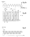
- a scale 110 is read by a readhead 112 provided by an array 114 of photo-emitting elements, and an analyser array 116 (which will not be described further).
- the photo-emitting array 114 effectively combines the functions of a light source and an index grating.
- the photo-emitting array 114 and analyser 116 are provided on the same semiconductor substrate, which is typically of gallium arsenide or some other suitable III/V semiconductor material.
- the photo-emitting array 114 comprises an area 118 which is a light emitting diode (LED) 120.
- LED light emitting diode
- One of the electrodes for the LED is provided by the common ground electrode 122 at the rear of the substrate.
- the other electrode for the LED 120 is a metallisation layer 124 on the front of the substrate.
- the metallisation layer 124 has the form of a grid pattern which defines elongate apertures 126. In an LED, most of the light emitted originates from areas of the semiconductor material which lie adjacent the electrode. Thus, the regions of the LED 120 which lie in register with the apertures 126 will emit light in a manner very similar to the passage of light through an index grating.
- This embodiment of the invention provides automatic coplanarity of the photo-emitting array 114 and analyser array 116, while reducing the expense of the apparatus by obviating the need for one or more optical gratings and detectors.
- This embodiment of the present invention may be particularly useful in an analogue, or scanning probe used, e.g. on a coordinate measuring machine, such as a probe described in WO90/04149 .
- the outputs of the sets A,B,C are combined in a number of possible ways to generate quadrature signals. It may be necessary to adjust the amplitude of the individual outputs A,B,C. In the prior art apparatus this is achieved by electrically amplifying or reducing the amplitude of the outputs from individual photodetectors. This is undesirable since additional electronics are required.
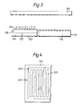
- a third embodiment of the present invention enables the optical equalisation of the output amplitudes of the signals from individual sets of photo-sensitive elements.
- an analyser 160 has a silicon substrate 162 having, on its surface, a plurality of spaced apart photo-sensitive elements 164 each separated from an adjacent element 164 by an insulating guard diode (not shown).
- the elements 64 are divided into 4 sets A,B,C,D and the elements 64 are interleaved in a repeating pattern A,B,C,D, A,B,C,D; elements of a given set are connected in common.
- the array 160 may, for the purposes of illustration, be divided into two portions 170,172.
- Portion 170 of the array includes light sensitive elements 164 wherein the elements 164 of the sets A and B are longitudinally extended in a direction perpendicular to the direction of spacing of the elements with the elements of set A being extended in the opposite direction to the elements of the set B.
- the elements 164 of sets A and B in portion 170 of the array are thus approximately 10-15% longer than the elements 164 of the sets C and D.
- Shutters 174,176 are each movable between a first position, and a second position at which part of the array is obscured; specifically, the part of the array on which the extended parts of the elements 164 of the sets A and B lie.
- Portion 172 includes, as with portion 170, four sets of elements A,B,C,D interleaved in a repeating pattern, and with elements of a given set being connected in common (both with each other and with the elements of the corresponding set in portion 170 of the array).
- elements of the sets C,D are extended longitudinally and shutters 178,180 respectively are provided to enable adjustment of the signal strength output from the sets of elements C,D.
- the present invention also provides optical adjustment of the relative phase.
- an analyser array 200 comprises a series of elongate photo-sensitive elements 202 extending substantially in the Y direction, and spaced apart in the X direction.
- the elements 202 are divided into three sets A,B,C and are interleaved on the array in a repeating pattern; the outputs of elements of a given set are connected in common.
- the elements 202 of the sets A and C extend substantially parallel both to each other and to the Y direction.
- the elements of the set B extend at a small angle ⁇ to the Y direction.
- a phase-shutter 204 is provided over the upper ends of the elements 202 and masks part of the elements 202 from the periodic light pattern.
- the spacing of the elements 202 and the angle at which the elements of set B are slanted relative to the elements of sets A and C is such that when the displacement of the shutter 204 is at the reference displacement R, the centre of area of the exposed portion of the elements 202 of the sets A and B are separated by the same distance in the X direction as the centre of area of the exposed portions of the elements 202 of the sets B and C.
- the spacing of the elements 202 relative to the pitch P of the periodic light pattern is such that, at the reference displacement R of the shutter 204, the centres of areas of the elements 202 of the sets A and B, and the elements 202 of the sets B and C are spaced from each other by a distance equal to 11 ⁇ 4 pitches P of the periodic light pattern, corresponding to a phase-shift of 360° + 90°.
- the spacing between the elements 202 of the sets C and A is equal to 11 ⁇ 2 pitches P, and thus corresponds to a phase-shift of 360° + 180°.
- each of the outputs A,B,C is represented by an arrow whose angular displacement corresponds to the phase of the output, and whose length corresponds to its magnitude (i.e. amplitude).
- the output of the elements 202 of the set A leads the output of the elements 202 of the set B by 90°; similarly the output of the elements 202 of the set B leads the output of the elements 202 of the set C by 90°.
- N.B. In general, in order that the outputs of the elements 5 202 may vary cyclically upon relative movement of the scale and readhead, the width over which each element extends in the X direction-should be a maximum of half the pitch of the light pattern.
- the outputs of the sets A,B,C may be combined according to the combination scheme (A-B), (B-C) to generate two signals having a quadrature relationship. This is only true however provided that the magnitude (i.e. amplitude) of the outputs is equal, and that the phase-shift between the outputs is exactly 90°. Should either the magnitude, or the phase of any one set of elements vary relative to the magnitude or phase of any of the other sets of elements then the resultant signals (A-B), (B-C) will not have a quadrature relationship; errors in the measurement of the position of the readhead relative to the scale will result.
- Amplitude adjustment is provided, as with the previous embodiment, by longitudinally extending elements 102 of the set C (for example), and providing a shutter 206 to adjust the exposed area of these elements.
- the relative phase of the outputs of elements of the set B is adjusted by movement of the shutter 204 in the Y direction. This has no appreciable effect on the relative amplitude of the output signals from the sets A,B,C, since the phase shutter masks substantially equal amounts of each of the elements 102 of all the sets. However, because the elements 202 of the set B extend at a small angle ⁇ relative to the Y direction, the position of the centre of area of these elements in the X direction shifts in accordance with the displacement of the phase shutter 204.
- the centre of area of elements 202 of the set B will shift toward elements 202 of the set A and the phase angle between the output of elements of set B and the outputs of elements of set A will decrease.
- the phase shutter 204 is projected from the reference position R then the centre of area of elements of set B will move toward elements of the set C and the phase angle between the output of these two sets of elements will decrease.
- the angle ⁇ is a small angle of the order of 1°.
- the elements of one set are shaped so that one end is asymmetrically tapered, thus providing a lateral shift of the centre of area of these elements when a phase shutter is displaced appropriately.
Landscapes
- Physics & Mathematics (AREA)
- General Physics & Mathematics (AREA)
- Optical Transform (AREA)
- Details Of Measuring Devices (AREA)
Claims (7)
- Un appareil de lecture à échelle opto-électronique comprenant une échelle définie par une série de lignes espacées et une tête de lecture se déplaçant par rapport à l'échelle dans le sens de l'espacement des lignes afin de générer un signal de sortie permettant de déterminer l'amplitude et la direction du mouvement relatif de l'échelle et de la tête de lecture, la tête de lecture comprenant :des moyens (10,12) d'éclairage de l'échelle et de production, dans un plan image, d'un motif lumineux périodique variant de façon cyclique en intensité dans la direction de l'espacement des lignes de l'échelle, ledit motif lumineux ayant un pas égal ou inférieur à celui des lignes d'échelle ; une variation cyclique correspondante de l'intensité de lumière à un point donné sur ledit plan résultant du mouvement relatif de ladite échelle et de ladite tête de lecture ;un analyseur (16) placé dans le même plan, comprenant un groupe d'éléments allongés (24) ayant une surface photosensible exposée audit motif lumineux périodique, lesdits éléments étant espacés dans la direction d'espacement des lignes de l'échelle et transversalement à leur longueur, lesdits éléments étant groupés en plusieurs jeux (A,B,C), les éléments d'un ensemble donné (24A, 24B, 24C) étant raccordés entre eux, tous lesdits éléments étant intercalés avec des éléments d'un jeu différent suivant un motif répétitif et où les centres des surfaces photosensibles exposées de tous les éléments d'un jeu donné sont espacés d'une distance égale au multiple entier non zéro du pas (P) du motif lumineux ;avec comme caractéristiques :les centres des surfaces photosensibles exposées des éléments adjacents sont espacés de distances égales aux sommes des multiples entiers non zéro du pas du motif lumineux et de fractions non zéro dudit pas correspondant à un angle de phase prédéterminé entre lesdits éléments adjacents par rapport au motif lumineux périodique, lesdites fractions étant toutes ¼ dudit pas ; ou bien lesdites fractions étant toutes 1/3 dudit pas ; ou bien en présence seulement de trois ensembles d'éléments et lesdites fractions étant respectivement ¼, ¼ et ½ dudit pas.
- Un appareil conforme à la revendication 1 dans lequel les éléments (202B) d'un premier desdits jeux forment un petit angle (8) avec les éléments (202A, 202C) des autres jeux, l'appareil comprenant aussi un obturateur de phase rétractif (206) afin de varier l'étendue des surfaces photosensibles desdits éléments exposés audit motif lumineux périodique et ainsi variant l'espacement entre les centres des surfaces photosensibles exposées des éléments (202B) dudit premier jeu et les centres des surfaces photosensibles exposées des éléments desdits autres jeux.
- Appareil conforme à la revendication 1 dans lequel ladite distance entre éléments adjacents est de 11/3 du pas marginal.
- Appareil conforme à la revendication 1 dans lequel ladite distance entre éléments adjacents est de 1¼ du pas marginal.
- Appareil conforme à l'une quelconque des revendications qui précèdent dans lequel ledit analyseur comprend aussi une diode de protection (26) placée entre chaque paire d'éléments adjacents.
- Appareil conforme à la revendication 1 comprenant aussi un obturateur d'amplitude (74;76;78;80) rétractif par rapport à une position à laquelle l'obturateur d'amplitude obscurcit une partie du groupe où un seul desdits jeux (A;B;C;D) d'éléments a des surfaces photosensibles se trouvant sur ladite partie du groupe pouvant être obscurcie par l'obturateur d'amplitude.
- Appareil conforme à la revendication 6 comprenant aussi plusieurs obturateurs d'amplitude, chacun étant prévu pour un seul desdits jeux d'éléments.
Priority Applications (1)
| Application Number | Priority Date | Filing Date | Title |
|---|---|---|---|
| EP98101805A EP0843159A3 (fr) | 1991-11-06 | 1992-10-27 | Dispositif optoélectronique pour lire des échelles |
Applications Claiming Priority (6)
| Application Number | Priority Date | Filing Date | Title |
|---|---|---|---|
| GB919123567A GB9123567D0 (en) | 1991-11-06 | 1991-11-06 | Opto-electronic scale reading apparatus |
| GB9123567 | 1991-11-06 | ||
| GB9206750 | 1992-03-27 | ||
| GB929206750A GB9206750D0 (en) | 1992-03-27 | 1992-03-27 | Opto-electronic scale reading apparatus |
| GB929208898A GB9208898D0 (en) | 1992-04-24 | 1992-04-24 | Opto-electronic scale reading apparatus |
| GB9208898 | 1992-04-24 |
Related Child Applications (1)
| Application Number | Title | Priority Date | Filing Date |
|---|---|---|---|
| EP98101805A Division EP0843159A3 (fr) | 1991-11-06 | 1992-10-27 | Dispositif optoélectronique pour lire des échelles |
Publications (3)
| Publication Number | Publication Date |
|---|---|
| EP0543513A1 EP0543513A1 (fr) | 1993-05-26 |
| EP0543513B1 EP0543513B1 (fr) | 1998-09-16 |
| EP0543513B2 true EP0543513B2 (fr) | 2007-10-24 |
Family
ID=27265916
Family Applications (2)
| Application Number | Title | Priority Date | Filing Date |
|---|---|---|---|
| EP92309807A Expired - Lifetime EP0543513B2 (fr) | 1991-11-06 | 1992-10-27 | Dispositif opto-électronique de lecture d'une échelle graduée |
| EP98101805A Withdrawn EP0843159A3 (fr) | 1991-11-06 | 1992-10-27 | Dispositif optoélectronique pour lire des échelles |
Family Applications After (1)
| Application Number | Title | Priority Date | Filing Date |
|---|---|---|---|
| EP98101805A Withdrawn EP0843159A3 (fr) | 1991-11-06 | 1992-10-27 | Dispositif optoélectronique pour lire des échelles |
Country Status (4)
| Country | Link |
|---|---|
| US (1) | US5302820A (fr) |
| EP (2) | EP0543513B2 (fr) |
| JP (1) | JPH05248895A (fr) |
| DE (1) | DE69227009T3 (fr) |
Families Citing this family (34)
| Publication number | Priority date | Publication date | Assignee | Title |
|---|---|---|---|---|
| GB9424969D0 (en) * | 1994-12-10 | 1995-02-08 | Renishaw Plc | Opto-electronic scale reading apparatus |
| GB9425907D0 (en) * | 1994-12-22 | 1995-02-22 | Renishaw Plc | Opto-electronic scale reading apparatus |
| GB2299726B (en) * | 1995-04-07 | 1999-07-28 | Rank Cintel Ltd | Diffusers for film scanners and the like |
| GB9522491D0 (en) * | 1995-11-02 | 1996-01-03 | Renishaw Plc | Opto-electronic rotary encoder |
| JP3631551B2 (ja) * | 1996-01-23 | 2005-03-23 | 株式会社ミツトヨ | 光学式エンコーダ |
| JPH11281403A (ja) * | 1998-03-27 | 1999-10-15 | Futaba Corp | 光学式リニヤスケール原点信号発生装置 |
| DE19859670A1 (de) * | 1998-12-23 | 2000-06-29 | Heidenhain Gmbh Dr Johannes | Abtastkopf und Verfahren zu dessen Herstellung |
| DE19859669A1 (de) * | 1998-12-23 | 2000-06-29 | Heidenhain Gmbh Dr Johannes | Integrierter optoelektronischer Sensor und Verfahren zu dessen Herstellung |
| DE19917950A1 (de) * | 1999-04-21 | 2000-10-26 | Heidenhain Gmbh Dr Johannes | Integrierter optoelektronischer Dünnschichtsensor und Verfahren zu dessen Herstellung |
| JP4350220B2 (ja) * | 1999-08-06 | 2009-10-21 | 株式会社ミツトヨ | 変位測定装置 |
| DE19944004A1 (de) | 1999-09-14 | 2001-03-15 | Kostal Leopold Gmbh & Co Kg | Optoelektronischer Drehwinkelsensor |
| GB9924331D0 (en) * | 1999-10-15 | 1999-12-15 | Renishaw Plc | Scale reading apparatus |
| GB9924332D0 (en) | 1999-10-15 | 1999-12-15 | Renishaw Plc | Producing a scale for use in opto-electronic scale reading apparatus |
| GB9928483D0 (en) | 1999-12-03 | 2000-02-02 | Renishaw Plc | Opto-electronic scale reading apparatus |
| US6512222B2 (en) * | 2000-02-03 | 2003-01-28 | Mitutoyo Corporation | Displacement measuring apparatus |
| GB0004120D0 (en) | 2000-02-23 | 2000-04-12 | Renishaw Plc | Opto-electronic scale reading apparatus |
| ES2166717B1 (es) * | 2000-06-15 | 2003-04-16 | Fagor S Coop | Disposicion optoelectronica de fotodetectores para la medicion de longitud. |
| GB0023289D0 (en) * | 2000-09-22 | 2000-11-08 | Renishaw Plc | Determination of displacement |
| GB0103582D0 (en) * | 2001-02-14 | 2001-03-28 | Renishaw Plc | Position determination system |
| US6794638B2 (en) | 2001-09-13 | 2004-09-21 | Mitutoyo Corporation | Photoelectric encoder having improved light-emitting and photoreceptive sections |
| US7145126B2 (en) | 2004-03-16 | 2006-12-05 | Wai-Hon Lee | Optical position encoder device using incoherent light source |
| JP4803641B2 (ja) * | 2005-05-12 | 2011-10-26 | オリンパス株式会社 | 光学式エンコーダ |
| EP1722200B1 (fr) * | 2005-05-13 | 2008-02-13 | FAGOR, S.Coop | Dispositif de mesure optoelectronique |
| GB0522651D0 (en) | 2005-11-07 | 2005-12-14 | Renishaw Plc | Scale and readhead system |
| GB0523273D0 (en) | 2005-11-16 | 2005-12-21 | Renishaw Plc | Scale and readhead apparatus and method |
| GB0601174D0 (en) | 2006-01-20 | 2006-03-01 | Renishaw Plc | Multiple readhead apparatus |
| EP1852674B1 (fr) * | 2006-05-05 | 2015-09-09 | Dr. Johannes Heidenhain GmbH | Dispositif de mesure destiné à la détermination du déplacement relatif entre deux composants |
| GB0621487D0 (en) * | 2006-10-28 | 2006-12-06 | Renishaw Plc | Opto-electronic read head |
| JP2010256080A (ja) | 2009-04-22 | 2010-11-11 | Mitsutoyo Corp | 光電式エンコーダ及びその動作制御方法 |
| DE102011075286A1 (de) * | 2011-05-05 | 2012-11-08 | Dr. Johannes Heidenhain Gmbh | Optische Positionsmesseinrichtung |
| US9562793B2 (en) | 2014-11-17 | 2017-02-07 | Mitutoyo Corporation | Illumination portion for an optical encoder |
| US9689715B2 (en) | 2015-05-19 | 2017-06-27 | Mitutoyo Corporation | Light source array used in an illumination portion of an optical encoder |
| US10243668B2 (en) | 2016-04-27 | 2019-03-26 | Industrial Technology Research Institute | Positioning measurement device and the method thereof |
| CN112556734B (zh) * | 2020-11-30 | 2021-09-28 | 中国科学院长春光学精密机械与物理研究所 | 光电编码器莫尔条纹细分方法 |
Family Cites Families (12)
| Publication number | Priority date | Publication date | Assignee | Title |
|---|---|---|---|---|
| GB1231029A (fr) * | 1968-12-13 | 1971-05-05 | ||
| GB1311275A (en) * | 1969-06-04 | 1973-03-28 | Ferranti Ltd | Measuring apparatus employing optical gratings |
| GB1504691A (en) * | 1974-03-15 | 1978-03-22 | Nat Res Dev | Measurement apparatus |
| DD206424A1 (de) * | 1982-04-15 | 1984-01-25 | Franz Klapper | Einrichtung zur messung von verschiebungen und verdrehungen eines koerpers |
| IT1160210B (it) * | 1983-09-30 | 1987-03-04 | Olivetti & Co Spa | Trasduttore ottico per rilevare la posizione di un organo mobile rispetto ad una struttura fissa |
| JPS61178612A (ja) * | 1985-02-04 | 1986-08-11 | Kobe Steel Ltd | 光電式ロ−タリエンコ−ダ |
| US4691101A (en) * | 1985-06-19 | 1987-09-01 | Hewlett-Packard Company | Optical positional encoder comprising immediately adjacent detectors |
| DE3616144A1 (de) * | 1986-05-14 | 1987-11-19 | Heidenhain Gmbh Dr Johannes | Fotoelektrische messeinrichtung |
| JPS63274563A (ja) * | 1987-05-07 | 1988-11-11 | Matsushita Electric Ind Co Ltd | 光プリンタヘッド用モノリシック発光素子アレイ |
| US5017776A (en) * | 1989-03-10 | 1991-05-21 | Hewlett-Packard Company | Apparatus for and methods of optical encoding having spiral shaped light modulator |
| GB9023659D0 (en) * | 1990-10-31 | 1990-12-12 | Renishaw Plc | Opto-electronic scale reading apparatus |
| US5155355A (en) * | 1991-04-25 | 1992-10-13 | Mitutoyo Corporation | Photoelectric encoder having a grating substrate with integral light emitting elements |
-
1992
- 1992-10-27 EP EP92309807A patent/EP0543513B2/fr not_active Expired - Lifetime
- 1992-10-27 DE DE69227009T patent/DE69227009T3/de not_active Expired - Lifetime
- 1992-10-27 EP EP98101805A patent/EP0843159A3/fr not_active Withdrawn
- 1992-11-06 JP JP4297236A patent/JPH05248895A/ja active Pending
-
1993
- 1993-06-07 US US08/072,693 patent/US5302820A/en not_active Expired - Lifetime
Also Published As
| Publication number | Publication date |
|---|---|
| EP0843159A3 (fr) | 1999-06-02 |
| JPH05248895A (ja) | 1993-09-28 |
| EP0543513A1 (fr) | 1993-05-26 |
| EP0843159A2 (fr) | 1998-05-20 |
| DE69227009T2 (de) | 1999-02-18 |
| DE69227009D1 (de) | 1998-10-22 |
| US5302820A (en) | 1994-04-12 |
| EP0543513B1 (fr) | 1998-09-16 |
| DE69227009T3 (de) | 2008-05-29 |
Similar Documents
| Publication | Publication Date | Title |
|---|---|---|
| EP0543513B2 (fr) | Dispositif opto-électronique de lecture d'une échelle graduée | |
| US5889280A (en) | Apparatus for measuring displacement | |
| US6392224B1 (en) | Scanning unit for an optical position measuring device | |
| JP3045452B2 (ja) | 光電測長または測角装置 | |
| JP3644687B2 (ja) | 2つの物体の相対的な変位を測定する光電式距離及び角度測定装置 | |
| US7098446B2 (en) | Photoelectric encoder | |
| JP5974329B2 (ja) | 光電式エンコーダ | |
| US6610975B2 (en) | Optical encoder | |
| JPH0711433B2 (ja) | 光電位置測定装置 | |
| US6906311B2 (en) | Photoelectric encoder | |
| EP0694764B1 (fr) | Rangée de détecteurs destinée aux systèmes de mesure interférométriques | |
| US6965437B2 (en) | Scanning unit for an optical position measuring device | |
| US7268883B2 (en) | Optoelectronic harmonically filtered detector system for a scanning unit | |
| JP2000321097A (ja) | 光学式エンコーダ | |
| US7095011B2 (en) | Photoelectric encoder for precise measurements | |
| JPH09126818A (ja) | 光電測長または測角装置 | |
| JP4401852B2 (ja) | 光学式変位測定装置 | |
| JP4667629B2 (ja) | 光学式エンコーダ | |
| JP2001272252A (ja) | 光学式エンコーダ装置 | |
| JPH0235308A (ja) | 位置検出方法 | |
| JPH02143113A (ja) | 光学式エンコーダ |
Legal Events
| Date | Code | Title | Description |
|---|---|---|---|
| PUAI | Public reference made under article 153(3) epc to a published international application that has entered the european phase |
Free format text: ORIGINAL CODE: 0009012 |
|
| AK | Designated contracting states |
Kind code of ref document: A1 Designated state(s): CH DE ES FR GB IT LI |
|
| 17P | Request for examination filed |
Effective date: 19931106 |
|
| 17Q | First examination report despatched |
Effective date: 19941110 |
|
| GRAG | Despatch of communication of intention to grant |
Free format text: ORIGINAL CODE: EPIDOS AGRA |
|
| GRAG | Despatch of communication of intention to grant |
Free format text: ORIGINAL CODE: EPIDOS AGRA |
|
| GRAH | Despatch of communication of intention to grant a patent |
Free format text: ORIGINAL CODE: EPIDOS IGRA |
|
| GRAH | Despatch of communication of intention to grant a patent |
Free format text: ORIGINAL CODE: EPIDOS IGRA |
|
| GRAA | (expected) grant |
Free format text: ORIGINAL CODE: 0009210 |
|
| ITF | It: translation for a ep patent filed |
Owner name: BARZANO' E ZANARDO MILANO S.P.A. |
|
| AK | Designated contracting states |
Kind code of ref document: B1 Designated state(s): CH DE ES FR GB IT LI |
|
| PG25 | Lapsed in a contracting state [announced via postgrant information from national office to epo] |
Ref country code: LI Free format text: LAPSE BECAUSE OF FAILURE TO SUBMIT A TRANSLATION OF THE DESCRIPTION OR TO PAY THE FEE WITHIN THE PRESCRIBED TIME-LIMIT Effective date: 19980916 Ref country code: FR Free format text: LAPSE BECAUSE OF FAILURE TO SUBMIT A TRANSLATION OF THE DESCRIPTION OR TO PAY THE FEE WITHIN THE PRESCRIBED TIME-LIMIT Effective date: 19980916 Ref country code: CH Free format text: LAPSE BECAUSE OF FAILURE TO SUBMIT A TRANSLATION OF THE DESCRIPTION OR TO PAY THE FEE WITHIN THE PRESCRIBED TIME-LIMIT Effective date: 19980916 |
|
| REG | Reference to a national code |
Ref country code: CH Ref legal event code: EP |
|
| REF | Corresponds to: |
Ref document number: 69227009 Country of ref document: DE Date of ref document: 19981022 |
|
| EN | Fr: translation not filed | ||
| PG25 | Lapsed in a contracting state [announced via postgrant information from national office to epo] |
Ref country code: ES Free format text: LAPSE BECAUSE OF FAILURE TO SUBMIT A TRANSLATION OF THE DESCRIPTION OR TO PAY THE FEE WITHIN THE PRESCRIBED TIME-LIMIT Effective date: 19990318 |
|
| REG | Reference to a national code |
Ref country code: CH Ref legal event code: PL |
|
| PLBI | Opposition filed |
Free format text: ORIGINAL CODE: 0009260 |
|
| PLBF | Reply of patent proprietor to notice(s) of opposition |
Free format text: ORIGINAL CODE: EPIDOS OBSO |
|
| 26 | Opposition filed |
Opponent name: DR. JOHANNES HEIDENHAIN GMBH Effective date: 19990611 |
|
| PLBF | Reply of patent proprietor to notice(s) of opposition |
Free format text: ORIGINAL CODE: EPIDOS OBSO |
|
| PLBF | Reply of patent proprietor to notice(s) of opposition |
Free format text: ORIGINAL CODE: EPIDOS OBSO |
|
| PLBF | Reply of patent proprietor to notice(s) of opposition |
Free format text: ORIGINAL CODE: EPIDOS OBSO |
|
| RDAH | Patent revoked |
Free format text: ORIGINAL CODE: EPIDOS REVO |
|
| APAC | Appeal dossier modified |
Free format text: ORIGINAL CODE: EPIDOS NOAPO |
|
| APAE | Appeal reference modified |
Free format text: ORIGINAL CODE: EPIDOS REFNO |
|
| APAC | Appeal dossier modified |
Free format text: ORIGINAL CODE: EPIDOS NOAPO |
|
| REG | Reference to a national code |
Ref country code: GB Ref legal event code: IF02 |
|
| APBU | Appeal procedure closed |
Free format text: ORIGINAL CODE: EPIDOSNNOA9O |
|
| PLAY | Examination report in opposition despatched + time limit |
Free format text: ORIGINAL CODE: EPIDOSNORE2 |
|
| PLAH | Information related to despatch of examination report in opposition + time limit modified |
Free format text: ORIGINAL CODE: EPIDOSCORE2 |
|
| PLBC | Reply to examination report in opposition received |
Free format text: ORIGINAL CODE: EPIDOSNORE3 |
|
| APAH | Appeal reference modified |
Free format text: ORIGINAL CODE: EPIDOSCREFNO |
|
| APBP | Date of receipt of notice of appeal recorded |
Free format text: ORIGINAL CODE: EPIDOSNNOA2O |
|
| APAH | Appeal reference modified |
Free format text: ORIGINAL CODE: EPIDOSCREFNO |
|
| APBU | Appeal procedure closed |
Free format text: ORIGINAL CODE: EPIDOSNNOA9O |
|
| PUAH | Patent maintained in amended form |
Free format text: ORIGINAL CODE: 0009272 |
|
| STAA | Information on the status of an ep patent application or granted ep patent |
Free format text: STATUS: PATENT MAINTAINED AS AMENDED |
|
| 27A | Patent maintained in amended form |
Effective date: 20071024 |
|
| AK | Designated contracting states |
Kind code of ref document: B2 Designated state(s): CH DE ES FR GB IT LI |
|
| REG | Reference to a national code |
Ref country code: GB Ref legal event code: 732E |
|
| REG | Reference to a national code |
Ref country code: ES Ref legal event code: FD2A Effective date: 19981028 |
|
| EN | Fr: translation not filed | ||
| PGFP | Annual fee paid to national office [announced via postgrant information from national office to epo] |
Ref country code: DE Payment date: 20101022 Year of fee payment: 19 |
|
| PGFP | Annual fee paid to national office [announced via postgrant information from national office to epo] |
Ref country code: IT Payment date: 20101027 Year of fee payment: 19 Ref country code: GB Payment date: 20101021 Year of fee payment: 19 |
|
| REG | Reference to a national code |
Ref country code: DE Ref legal event code: R071 Ref document number: 69227009 Country of ref document: DE |
|
| REG | Reference to a national code |
Ref country code: DE Ref legal event code: R071 Ref document number: 69227009 Country of ref document: DE |
|
| REG | Reference to a national code |
Ref country code: GB Ref legal event code: PE20 Expiry date: 20121026 |
|
| PG25 | Lapsed in a contracting state [announced via postgrant information from national office to epo] |
Ref country code: GB Free format text: LAPSE BECAUSE OF EXPIRATION OF PROTECTION Effective date: 20121026 |