EP0542954B1 - Elektrolytische Beschichtungszelle - Google Patents
Elektrolytische Beschichtungszelle Download PDFInfo
- Publication number
- EP0542954B1 EP0542954B1 EP92910718A EP92910718A EP0542954B1 EP 0542954 B1 EP0542954 B1 EP 0542954B1 EP 92910718 A EP92910718 A EP 92910718A EP 92910718 A EP92910718 A EP 92910718A EP 0542954 B1 EP0542954 B1 EP 0542954B1
- Authority
- EP
- European Patent Office
- Prior art keywords
- series
- ducts
- prismatic body
- electrolyte
- source
- Prior art date
- Legal status (The legal status is an assumption and is not a legal conclusion. Google has not performed a legal analysis and makes no representation as to the accuracy of the status listed.)
- Expired - Lifetime
Links
- 238000000576 coating method Methods 0.000 title claims description 17
- 239000011248 coating agent Substances 0.000 title claims description 16
- 239000003792 electrolyte Substances 0.000 claims abstract description 33
- 238000007747 plating Methods 0.000 claims abstract description 19
- 239000002184 metal Substances 0.000 claims description 18
- 229910052751 metal Inorganic materials 0.000 claims description 18
- 239000000758 substrate Substances 0.000 claims description 11
- 239000000463 material Substances 0.000 claims description 9
- 230000002745 absorbent Effects 0.000 claims 6
- 239000002250 absorbent Substances 0.000 claims 6
- 238000005253 cladding Methods 0.000 description 5
- 239000011148 porous material Substances 0.000 description 4
- PCHJSUWPFVWCPO-UHFFFAOYSA-N gold Chemical compound [Au] PCHJSUWPFVWCPO-UHFFFAOYSA-N 0.000 description 3
- 229910052737 gold Inorganic materials 0.000 description 3
- 239000010931 gold Substances 0.000 description 3
- 239000007788 liquid Substances 0.000 description 3
- 239000000243 solution Substances 0.000 description 3
- KDLHZDBZIXYQEI-UHFFFAOYSA-N Palladium Chemical compound [Pd] KDLHZDBZIXYQEI-UHFFFAOYSA-N 0.000 description 2
- 230000000295 complement effect Effects 0.000 description 2
- 238000001816 cooling Methods 0.000 description 2
- 230000008021 deposition Effects 0.000 description 2
- 239000008151 electrolyte solution Substances 0.000 description 2
- 229910021645 metal ion Inorganic materials 0.000 description 2
- 150000002739 metals Chemical class 0.000 description 2
- 229920002635 polyurethane Polymers 0.000 description 2
- 239000004814 polyurethane Substances 0.000 description 2
- 239000010970 precious metal Substances 0.000 description 2
- 229910017398 Au—Ni Inorganic materials 0.000 description 1
- 239000004952 Polyamide Substances 0.000 description 1
- 239000004743 Polypropylene Substances 0.000 description 1
- BQCADISMDOOEFD-UHFFFAOYSA-N Silver Chemical compound [Ag] BQCADISMDOOEFD-UHFFFAOYSA-N 0.000 description 1
- RTAQQCXQSZGOHL-UHFFFAOYSA-N Titanium Chemical compound [Ti] RTAQQCXQSZGOHL-UHFFFAOYSA-N 0.000 description 1
- NIXOWILDQLNWCW-UHFFFAOYSA-N acrylic acid group Chemical group C(C=C)(=O)O NIXOWILDQLNWCW-UHFFFAOYSA-N 0.000 description 1
- 230000032683 aging Effects 0.000 description 1
- 239000000956 alloy Substances 0.000 description 1
- 229910045601 alloy Inorganic materials 0.000 description 1
- 238000010276 construction Methods 0.000 description 1
- 238000005260 corrosion Methods 0.000 description 1
- 230000007797 corrosion Effects 0.000 description 1
- 238000010586 diagram Methods 0.000 description 1
- 238000009792 diffusion process Methods 0.000 description 1
- 238000006073 displacement reaction Methods 0.000 description 1
- 230000000694 effects Effects 0.000 description 1
- 238000005868 electrolysis reaction Methods 0.000 description 1
- 238000009713 electroplating Methods 0.000 description 1
- 239000006260 foam Substances 0.000 description 1
- MSNOMDLPLDYDME-UHFFFAOYSA-N gold nickel Chemical compound [Ni].[Au] MSNOMDLPLDYDME-UHFFFAOYSA-N 0.000 description 1
- 239000000203 mixture Substances 0.000 description 1
- 229910052763 palladium Inorganic materials 0.000 description 1
- 239000012466 permeate Substances 0.000 description 1
- UUWCBFKLGFQDME-UHFFFAOYSA-N platinum titanium Chemical compound [Ti].[Pt] UUWCBFKLGFQDME-UHFFFAOYSA-N 0.000 description 1
- 229920002647 polyamide Polymers 0.000 description 1
- 229920000728 polyester Polymers 0.000 description 1
- 229920000642 polymer Polymers 0.000 description 1
- -1 polypropylene Polymers 0.000 description 1
- 229920001155 polypropylene Polymers 0.000 description 1
- 229920000915 polyvinyl chloride Polymers 0.000 description 1
- 239000004800 polyvinyl chloride Substances 0.000 description 1
- 230000002028 premature Effects 0.000 description 1
- 238000003825 pressing Methods 0.000 description 1
- 238000005086 pumping Methods 0.000 description 1
- 238000011084 recovery Methods 0.000 description 1
- 229910052709 silver Inorganic materials 0.000 description 1
- 239000004332 silver Substances 0.000 description 1
- 230000003068 static effect Effects 0.000 description 1
- 229920002994 synthetic fiber Polymers 0.000 description 1
- 229920003002 synthetic resin Polymers 0.000 description 1
- 239000000057 synthetic resin Substances 0.000 description 1
- 239000004758 synthetic textile Substances 0.000 description 1
- 239000010936 titanium Substances 0.000 description 1
- 229910052719 titanium Inorganic materials 0.000 description 1
Images

Classifications
-
- C—CHEMISTRY; METALLURGY
- C25—ELECTROLYTIC OR ELECTROPHORETIC PROCESSES; APPARATUS THEREFOR
- C25D—PROCESSES FOR THE ELECTROLYTIC OR ELECTROPHORETIC PRODUCTION OF COATINGS; ELECTROFORMING; APPARATUS THEREFOR
- C25D5/00—Electroplating characterised by the process; Pretreatment or after-treatment of workpieces
- C25D5/04—Electroplating with moving electrodes
- C25D5/06—Brush or pad plating
Definitions
- the present invention relates to an electrolytic coating cell for forming a coating in the form of a longitudinal track on a metallic strip substrate intended to be connected to the negative pole of a current source, comprising a plating head having the form of an elongated prismatic body, at least one longitudinal portion of this prismatic body being formed of a metal profile intended to be connected to the positive pole of the current source, the external surface of this metal profile being coated with a layer of a material impregnable, a series of conduits distributed along the prismatic body and opening near the layer of wettable material, an electrolyte supply source, an electrolyte supply circuit, a supply circuit for said series of conduits, a pump for circulating the electrolyte from the source under pressure in the supply circuit, means for r bringing said metal substrate into contact with a longitudinal portion of the layer of wettable material covering said metal profile and means for producing a longitudinal displacement between said head and said substrate in order to form said longitudinal track.
- Such electrolytic plating cells are known for coating with a galvanic deposit a predetermined area of a plurality of metal parts arranged side by side in the form of an electrically continuous strip.
- a galvanic deposit a predetermined area of a plurality of metal parts arranged side by side in the form of an electrically continuous strip.
- Such a strip can be produced for example by stamping and cutting a metal strip so as to constitute a succession of separate lamellar pieces transverse to the strip, in particular electrical connectors, attached to a marginal zone of the strip intended to then be eliminated in order to separate separate rooms.
- plating cells in which a metallic substrate is continuously circulated in the form of a strip, this being connected to the negative potential of a current source to form the cathode, by putting a portion of the surface of the substrate. in contact with the surface of a flexible porous material impregnated with an electrolytic solution in contact with an anode. During this passage, the portion of the substrate in contact with the electrolytic solution is covered with a galvanic deposit, the thickness of which depends on the contact time and the electrolysis parameters, in particular the composition of the coating solution and the conditions plating (temperature, current density, etc.).
- Such a cell is described for example in document EP-A-195,781 (ROBBINS & CRAIG) in which a strip of vertically oriented connectors circulates horizontally and comes to rub against a belt of flexible porous material, for example a synthetic resin foam, in particular polyurethane, this belt itself being in circulation so that the active galvanic solution which permeates it is continuously renewed.
- a strip of vertically oriented connectors circulates horizontally and comes to rub against a belt of flexible porous material, for example a synthetic resin foam, in particular polyurethane, this belt itself being in circulation so that the active galvanic solution which permeates it is continuously renewed.
- a cladding head consisting of an elongated prismatic block slipped into a sleeve of porous material impregnated with galvanic solution.
- the parts to be plated are brought longitudinally into contact with an edge of the prismatic block, the angle of the latter, determining the width of the portion of porous sheet in contact with the parts and, thus, the extent of the area. plated with these.
- An illustration of such an embodiment is found in FIGS. 9, 10 and 11 of document EP-A 222 232 cited for reference.
- Figure 1 is a perspective view with partial section of a detail of a plating cell according to the prior art.
- Figure 2 is a perspective view of an embodiment of a plating head fitted to a cell according to the invention.
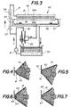
- FIG. 3 is a diagram of the electrolyte supply circuit of the plating head illustrated in FIG. 2.
- FIGS. 4 to 7 are partial section views of various variants of the front end of the veneer head of FIG. 2.
- FIG. 1 there is shown schematically some essential elements of a plating cell of connector strips for electronics; such cells are commercially available.
- a strip 1 of connector contacts joined by their base 1a and comprising a curved portion 1b, the convex part of which is coated with a layer of precious metal.
- This strip 1 is guided by a cathode contact rail 3 against a shoulder 3a from which the base 1a of the strip slides, held and driven by a roller 4, in the direction of the arrow 2.
- a flap slide 5 makes it so that maintain the area 1b of the contacts against an elongated portion of a cladding head 6.
- This cladding head 6 is formed of a prismatic body 7 made of platinum titanium covered with a static felt 8 of wettable material, for example a sleeve of synthetic textile or of woven or expanded polymer, in particular of polypropylene, polyurethane, PVC, polyamide. , polyester, polyacrylic or other.
- the front of the prismatic body 7 is in the form of a triangular prism 7b.
- the connectors to be pressed are pressed by the slide 5 against an edge 7a of this triangular prism 7b, so that the area of the contacts 1b to be pressed against these connectors is applied against the felt 8 covering the edge 7a.
- the prismatic body 7 comprises an electrolyte supply channel 9 connected, step by step, to lateral conduits 10 for irrigating the felt 8.
- the electrolyte reaches the latter through openings 11, through a buffer of porous material 11a intended to regulate its flow.
- the prismatic body 7 is connected to an anode supply terminal, the electrolyte passing through the conduits 9 and 10 thus being activated and allowing the metal dissolved in it to be galvanically deposited on the zone of the contacts 1b.
- the strip 1 is made to pass by pressing it against the edge 7a of the triangular prism 7b and the felt 8 is supplied under pressure with electrolyte, through the channels 9 and 10, via pumping elements not shown.
- Such a construction has certain limitations due mainly to the flow rate of the electrolyte in the felt.
- the electrolyte flow must remain low so as not to clog the felt and not to cause a runoff of liquid on the parts to be plated.
- a low electrolyte flow corresponds to a rapid depletion of its concentration of metal ions in the plating zone and to its premature cooling by lack of renewal of the liquid, resulting in a slow and not very economical plating.
- the cell of the present invention illustrated in Figure 2, overcomes the aforementioned drawbacks.
- This plating head comprises a prismatic body 20 formed of two acrylic parts 20a, 20b assembled by screws 28.
- the front of this body 20 is formed of a triangular prism 21, while the rear, of rectangular section, is fitted into a U-shaped profile 23.
- a felt sleeve 25 surrounds the prismatic body 20 and the profile 23.
- a spring 24 interposed between the rear face of the prismatic body 20 and the bottom of the profile 23 tends to separate these two parts from one another and thus serves to keep the felt sleeve 25 under tension.
- the two parts 20a, 20b forming the prismatic body 20 are shaped to form between them two longitudinal channels, one of semi-cylindrical shape to receive a perforated titanium tube 31 and intended to be connected to a source of electrolyte supply as will be seen below, the other channel 37 serving to bring the excess electrolyte back to the power source.
- a seal 27 is used to separate these two channels.
- These two parts 20a, 20b are also shaped to fix an added longitudinal profile 22 forming the dihedral of the front end of the triangular prism 21.
- This longitudinal profile has a plurality of grooves 34a, 34b extending in pairs transversely on the two faces of the dihedral, the pairs being spaced longitudinally from each other.
- Each groove 34a communicates with one end of a conduit 30, the other end of which communicates with the perforated tube 31 by means of a diffusion grid 32.
- Each groove 34b communicates with one end of a conduit 36, the another end opens into channel 37.
- This profile 22 is intended to be connected to the + pole of the current source and thus serves as an anode in the electrolytic coating process.
- the added longitudinal profile 22 has two faces adjacent to the conduits 30 respectively 36, a narrowed part 22a ending in a fixing element 22b of wider section than the narrowed part 22a.
- the parts 20a and 20b being shaped in this area in a manner complementary to the parts 22a and 22b of the attached longitudinal section 22, the latter is therefore secured to the prismatic body 20 following the assembly and fixing of the two parts 20a, 20b by the screws 28.
- the prismatic body 20 is seen seen from a plane containing the bisector of the dihedral angle of the triangular prism 21.
- This circuit further comprises a heated tank 50 to contain the electrolyte, a pump 51 intended to constantly put the electrolyte in circulation to maintain its homogeneous temperature, and a venturi 52 connected on the one hand to the outlet of the pump 51 by a bypass 31a and, on the other hand to the evacuation channel 37.
- the supply conduit 31 is also connected to the outlet of the pump 51 via an adjustment valve 53.
- a flow meter 54 placed downstream of the adjustment valve 53 makes it possible to read the flow of electrolyte sent through the prismatic body 20.
- a recovery tank 38 is used to recover possible electrolyte losses, in particular when adjusting the plating cell.
- a depression is created in the evacuation channel 37, by the electrolyte circulated by the pump 51.
- This depression acts at the outlet of the conduits 36 in the bottom of the grooves 34b, so that the the excess electrolyte is sucked into the conduits 36 and brought back to the tank 50 by the evacuation channel 37. Thanks to this suction of the excess electrolyte, it is therefore possible to fix a supply flow rate of the grooves 34a by the conduits 30 communicating with the perforated tube 31, sufficient to maintain the electrolyte in the felt 25 at an appropriate temperature and to constantly bring metal ions into the plating area in order to increase the speed of deposition, to improve its quality and control the thickness of the coating.
- the front end of the longitudinal section 22 is formed by the edge of the dihedral of the triangular prism 21.
- this edge can be truncated as illustrated by FIGS. 4 to 7.
- the profile 60 of FIGS. 4 and 5 is cut by a plane 61 inclined relative to the bisector of the angle formed by the extension of the faces of the triangular prism 21.
- This profile 60 can be used as illustrated by FIG. 4, that is to say on an edge, which amounts to obtaining the same effect as with the head of FIG. 2 or as illustrated by FIG. 5 where it is the plane 61 which is in contact with the surface to be plated 62.
- FIG. 7 illustrates a profile 66 the front of which is truncated by a surface 67 perpendicular to the bisector of the angle formed by the extension of the surfaces of the prism 21.
- the dimensions of the main members of the cladding head according to the invention are as follows:
- the quality of the deposit (resistance to wear) and the precision of the control of the coated surface were considered excellent.
Landscapes
- Chemical & Material Sciences (AREA)
- Engineering & Computer Science (AREA)
- Chemical Kinetics & Catalysis (AREA)
- Electrochemistry (AREA)
- Materials Engineering (AREA)
- Metallurgy (AREA)
- Organic Chemistry (AREA)
- Electroplating Methods And Accessories (AREA)
- Primary Cells (AREA)
- Electrolytic Production Of Metals (AREA)
Claims (7)
- Zelle zur elektrolytischen Abscheidung, um einen Überzug in Gestalt einer Längsbahn auf einem leistenförmigen Substrat (1) zu erzeugen, das dazu bestimmt ist, mit dem Minuspol einer Stromquelle verbunden zu werden, die Zelle bestehendaus einem Plattierkopf in der Gestalt eines gestreckten prismatischen Körpers (20),wobei wenigstens ein Längsabschnitt dieses prismatischen Körpers (20) durch ein Metallprofil (22) gebildet wird, das dazu bestimmt ist, mit dem Pluspol der Stromquelle verbunden zu werden,die Aussenflächen dieses Metallprofils (22) mit einer Schicht (25) aus einem tränkbaren Material überzogen sind undeine Reihe von Leitungen (30) entlang des prismatischen Körpers (20) verteilt ist und nahe der Schicht (25) aus tränkbarem Material mündet,aus einer Elektrolytversorgungseinheit (50),aus einem Kreis (31) zur Speisung der benannten Reihe von Leitungen (30),aus einer Pumpe (51), um den Elektrolyten von der Elektrolytversorgungseinheit (50) unter Druck im Speisekreis (31) in Umlauf zu bringen,aus Organen (5), um das benannte Metallsubstrat (1) mit einem Längsabschnitt der Schicht (25) aus tränkbarem Material, die das benannte Metallprofil bedeckt, in Berührung zu bringen, undaus Organen, um eine Längsverschiebung des benannten Kopfes gegen das benannte Substrat zustandezubringen, um die benannte Längsbahn zu erzeugen, dadurch gekennzeichnet, dassder benannte Plattierkopf eine zweite Reihe von längs verteilten Leitungen umfasst, die nahe der tränkbaren Schicht münden, unddass eine Ansaugeinheit (52) an diese zweite Reihe von Leitungen (36) angeschlossen ist.
- Abscheidezelle gemäss Anspruch 1, dadurch gekennzeichnet, dass von den beiden Reihen der entlang des benannten prismatischen Körpers verteilten Leitungen (30, 36) die eine sich auf der einen, die andere sich auf der anderen Seite des Längsabschnitts der Schicht aus tränkbarem Material befindet, mit der das benannte Metallsubstrat in Berührung gebracht wird, und eine Folge von Querkanälen (34a, 34b) jedes Paar aus jeweils einer Leitung der Reihe von Leitungen (30) und einer Leitung der Reihe von Leitungen (36) miteinander verbindet.
- Abscheidezelle gemäss Anspruch 1, dadurch gekennzeichnet, dass die beiden Reihen von Leitungen übereinander angeordnet sind, wobei die Reihe, deren Leitungen (30) an die Elektrolytversorgungseinheit (50) angeschlossen sind, sich über der Reihe befindet, deren Leitungen (36) an die Ansaugeinheit (52) angeschlossen sind.
- Abscheidezelle gemäss Anspruch 1, dadurch gekennzeichnet, dass der benannte prismatische Körper in zwei Längspartien (20a, 20b) unterteilt ist, die sich zu beiden Seiten des durch das benannte Metallprofil gebildeten Längsabschnitts erstrecken und so gestaltet sind, dass sie zwischen sich zwei Längskanäle (31, 37) freilassen, deren einer einerseits mit der ersten Reihe von Leitungen (30) und andererseits mit der benannten Elektrolyteinheit (50) in Verbindung steht, deren anderer einerseits mit der zweiten Reihe von Leitungen (36) und andererseits mit der benannten Ansaugeinheit (52) in Verbindung steht, und wobei sich je eine der benannten beiden Reihen von Leitungen auf den beiden Seiten des benannten Profilelements (22) erstreckt.
- Abscheidezelle gemäss Anspruch 1 oder Anspruch 4, dadurch gekennzeichnet, dass die Aussenflächen (22, 60, 63, 66) des benannten Profils in Abhängigkeit von der zu überziehenden Substratoberfläche gestaltet sind und dass dieses Profil austauschbar auf dem benannten prismatischen Körper angebracht ist.
- Abscheidezelle gemäss Anspruch 1, dadurch gekennzeichnet, dass die benannte Ansaugeinheit aus einem Venturirohr (52) besteht, das mit der benannten Pumpe über eine Zweigleitung (31a) verbunden ist, die dazu bestimmt ist, den Elektrolyten durch die Verengung des Venturirohres zu drücken, in die ein Überlaufkanal (37) mündet, der die benannte zweite Reihe von Leitungen (36) mit der Unterdruckzone des Venturirohres (52) verbindet.
- Abscheidezelle gemäss Anspruch 1, dadurch gekennzeichnet, dass die Schicht aus tränkbarem Material aus einem geschlossenen elastischen Band (25) besteht, das den prismatischen Körper (20) längs bedeckt, wobei das hintere Ende dieses Körpers in ein U-Profil (23) eingefügt ist und eine zwischen dem Boden des U-Profils (23) und dem hinteren Ende des prismatischen Körpers (20) angeordnete Feder (24) diese beiden Bauteile auseinanderdrückt und dadurch das Band (25) gespannt hält.
Applications Claiming Priority (3)
| Application Number | Priority Date | Filing Date | Title |
|---|---|---|---|
| CH1734/91 | 1991-06-11 | ||
| CH1734/91A CH684840A5 (fr) | 1991-06-11 | 1991-06-11 | Cellule pour plaquer par voie électrolytique sélectivement des zones choisies de pièces métalliques disposées en bande. |
| PCT/CH1992/000109 WO1992022685A1 (fr) | 1991-06-11 | 1992-06-09 | Cellule de revetement electrolytique |
Publications (2)
| Publication Number | Publication Date |
|---|---|
| EP0542954A1 EP0542954A1 (de) | 1993-05-26 |
| EP0542954B1 true EP0542954B1 (de) | 1996-04-17 |
Family
ID=4217345
Family Applications (1)
| Application Number | Title | Priority Date | Filing Date |
|---|---|---|---|
| EP92910718A Expired - Lifetime EP0542954B1 (de) | 1991-06-11 | 1992-06-09 | Elektrolytische Beschichtungszelle |
Country Status (8)
| Country | Link |
|---|---|
| US (1) | US5382343A (de) |
| EP (1) | EP0542954B1 (de) |
| JP (1) | JP2937480B2 (de) |
| AT (1) | ATE136951T1 (de) |
| CH (1) | CH684840A5 (de) |
| DE (1) | DE69209973T2 (de) |
| ES (1) | ES2089529T3 (de) |
| WO (1) | WO1992022685A1 (de) |
Families Citing this family (6)
| Publication number | Priority date | Publication date | Assignee | Title |
|---|---|---|---|---|
| FR2714080B1 (fr) * | 1993-12-16 | 1996-03-01 | Dalic | Dispositif pour le traitement électrochimique, notamment localisé, d'un substrat conducteur. |
| GB9400855D0 (en) * | 1994-01-18 | 1994-03-16 | Univ Warwick | Electrochemical deposition device and apparatus and method of electrochemical deposition using the same |
| US5830334A (en) * | 1996-11-07 | 1998-11-03 | Kobayashi; Hideyuki | Nozzle for fast plating with plating solution jetting and suctioning functions |
| FR2881146B1 (fr) * | 2005-01-27 | 2007-10-19 | Snecma Moteurs Sa | Procede de reparation d'une surface de frottement d'une aube a calage variable de turbomachine |
| NL2019743B1 (nl) | 2017-10-17 | 2019-04-24 | Meco Equipment Eng B V | Werkwijze voor het aanbrengen van een laag op een deel van het oppervlak van een substraat |
| US11352710B2 (en) * | 2019-09-30 | 2022-06-07 | Abdurrahman Ildeniz | Leak free brush electroplating system |
Family Cites Families (7)
| Publication number | Priority date | Publication date | Assignee | Title |
|---|---|---|---|---|
| JPS56102590A (en) * | 1979-08-09 | 1981-08-17 | Koichi Shimamura | Method and device for plating of microarea |
| DE3507927A1 (de) * | 1985-03-06 | 1986-09-11 | Dr.Ing.H.C. F. Porsche Ag, 7000 Stuttgart | Verfahren und handgeraet zum halbmechanischen verzinken von blechoberflaechen |
| JPS62139895A (ja) * | 1985-12-16 | 1987-06-23 | Electroplating Eng Of Japan Co | 部分メツキ装置 |
| JPS62211396A (ja) * | 1985-11-11 | 1987-09-17 | Electroplating Eng Of Japan Co | コネクタ−端子の微小部分のメツキ装置 |
| DE3839223C2 (de) * | 1988-11-19 | 1994-10-20 | Degussa | Vorrichtung zur selektiven galvanischen Beschichtung |
| US5116480A (en) * | 1990-03-26 | 1992-05-26 | The Carolinch Company | Method and apparatus for electrolytic plating |
| US5223110A (en) * | 1991-12-11 | 1993-06-29 | Microelectronics And Computer Technology Corporation | Apparatus for electroplating electrical contacts |
-
1991
- 1991-06-11 CH CH1734/91A patent/CH684840A5/fr not_active IP Right Cessation
-
1992
- 1992-06-09 ES ES92910718T patent/ES2089529T3/es not_active Expired - Lifetime
- 1992-06-09 WO PCT/CH1992/000109 patent/WO1992022685A1/fr not_active Ceased
- 1992-06-09 DE DE69209973T patent/DE69209973T2/de not_active Expired - Fee Related
- 1992-06-09 JP JP50974692A patent/JP2937480B2/ja not_active Expired - Fee Related
- 1992-06-09 EP EP92910718A patent/EP0542954B1/de not_active Expired - Lifetime
- 1992-06-09 AT AT92910718T patent/ATE136951T1/de not_active IP Right Cessation
-
1993
- 1993-02-08 US US07/983,554 patent/US5382343A/en not_active Expired - Lifetime
Also Published As
| Publication number | Publication date |
|---|---|
| DE69209973D1 (de) | 1996-05-23 |
| JP2937480B2 (ja) | 1999-08-23 |
| EP0542954A1 (de) | 1993-05-26 |
| CH684840A5 (fr) | 1995-01-13 |
| WO1992022685A1 (fr) | 1992-12-23 |
| ATE136951T1 (de) | 1996-05-15 |
| DE69209973T2 (de) | 1996-12-12 |
| US5382343A (en) | 1995-01-17 |
| ES2089529T3 (es) | 1996-10-01 |
| JPH06500364A (ja) | 1994-01-13 |
Similar Documents
| Publication | Publication Date | Title |
|---|---|---|
| WO1992022685A1 (fr) | Cellule de revetement electrolytique | |
| EP1567097A1 (de) | Zwischenwirbelkäfig mit mittigem verankerungsblatt | |
| EP0091147A2 (de) | Vorrichtung zum Aufstreichen einer Substanz auf ein bandförmiges Material | |
| EP3370821B1 (de) | Vorrichtung zum auftragen eines produktes zur verteilung auf der haut eines benutzers durch iontophorese | |
| FR2627407A1 (fr) | Chaine coupante pour scies a moteur a chaine | |
| FR2474371A1 (fr) | Dispositif de guidage de fil electrode pour machine d'usinage electrique | |
| FR2686624A1 (fr) | Structure d'electrode insoluble comportant des elements d'electrode amovibles et une plaque de base. | |
| EP0580730B2 (de) | Elektrode für eine elektrolytische zelle, deren gebrauch und verfahren | |
| FR2554833A1 (fr) | Dispositif pour le depot d'une couche d'un metal de recouvrement sur une bande metallique | |
| FR2889891A1 (fr) | Traversee de boitier et son procede de fabrication | |
| LU88492A1 (fr) | Procédé de fabrication d'une feuille métallique et dispositif de formation de films anodisés dans ce procéd' | |
| US4786389A (en) | Electroplating apparatus | |
| EP0792178B1 (de) | Ionophoretische vorrichtung zur transdermalen verabreichung von medikamenten undentsprechende wegwerfeinheit | |
| US4220504A (en) | Selective electroplating | |
| FR2720411A1 (fr) | Structure d'électrode à matériau électroconducteur élastique. | |
| FR2643499A2 (fr) | Potentiometre commandable par une contrainte mecanique reduite | |
| EP0246175B1 (de) | Gegenstrom-Elektrolyt-Einspritzer | |
| NL8520203A (nl) | Continu werkzame contactplateringswerkwijze en -inrichting. | |
| EP0002627A1 (de) | Schleifbürste für Stromabnehmer | |
| EP0254703A1 (de) | Verfahren und Vorrichtung zum elektrolytischen Verzinken von Stahlband | |
| FR2502189A1 (fr) | Dispositif de depot galvanique d'un revetement metallique unilateral sur un feuillard metallique, en particulier, un feuillard d'acier | |
| EP0798614A1 (de) | Boden für Uhrengehäuse, mit diesem Boden ausgerüstete Uhr und Schmuckstück | |
| EP2729983B1 (de) | Gasverteiler- und kompressionsstruktur für brennstoffzellenmodul und brennstoffzellensystem | |
| FR3149795A1 (fr) | Dispositif de traitement de la peau | |
| EP0294358B1 (de) | Electrode für eine Elektrolysezelle |
Legal Events
| Date | Code | Title | Description |
|---|---|---|---|
| PUAI | Public reference made under article 153(3) epc to a published international application that has entered the european phase |
Free format text: ORIGINAL CODE: 0009012 |
|
| 17P | Request for examination filed |
Effective date: 19930205 |
|
| AK | Designated contracting states |
Kind code of ref document: A1 Designated state(s): AT BE CH DE DK ES FR GB IT LI LU NL SE |
|
| 17Q | First examination report despatched |
Effective date: 19950509 |
|
| GRAH | Despatch of communication of intention to grant a patent |
Free format text: ORIGINAL CODE: EPIDOS IGRA |
|
| GRAA | (expected) grant |
Free format text: ORIGINAL CODE: 0009210 |
|
| ITPR | It: changes in ownership of a european patent |
Owner name: C.NE EPO REG. 20;SUNTEC TRADING. AG |
|
| AK | Designated contracting states |
Kind code of ref document: B1 Designated state(s): AT BE CH DE DK ES FR GB IT LI LU NL SE |
|
| PG25 | Lapsed in a contracting state [announced via postgrant information from national office to epo] |
Ref country code: DK Effective date: 19960417 |
|
| REF | Corresponds to: |
Ref document number: 136951 Country of ref document: AT Date of ref document: 19960515 Kind code of ref document: T |
|
| REG | Reference to a national code |
Ref country code: CH Ref legal event code: PUE Owner name: EESA ELECTROPLATING ENGINEERS S.A. TRANSFER- SUNTE |
|
| REF | Corresponds to: |
Ref document number: 69209973 Country of ref document: DE Date of ref document: 19960523 |
|
| RAP2 | Party data changed (patent owner data changed or rights of a patent transferred) |
Owner name: SUNTEC TRADING AG |
|
| ITF | It: translation for a ep patent filed | ||
| REG | Reference to a national code |
Ref country code: CH Ref legal event code: PFA Free format text: SUNTEC TRADING AG,MARCOUP 15,MUNTELIER (CH) TRANSFER- SUNTEC TRADING AG.,PA TREUHAND FUCHS DE CASTELLAWEG 27,GRENG (CH) Ref country code: CH Ref legal event code: NV Representative=s name: MOINAS KIEHL SAVOYE & CRONIN |
|
| NLT2 | Nl: modifications (of names), taken from the european patent patent bulletin |
Owner name: SUNTEC TRADING AG |
|
| GBT | Gb: translation of ep patent filed (gb section 77(6)(a)/1977) |
Effective date: 19960723 |
|
| RAP2 | Party data changed (patent owner data changed or rights of a patent transferred) |
Owner name: SUNTEC TRADING AG |
|
| REG | Reference to a national code |
Ref country code: ES Ref legal event code: FG2A Ref document number: 2089529 Country of ref document: ES Kind code of ref document: T3 |
|
| NLT2 | Nl: modifications (of names), taken from the european patent patent bulletin |
Owner name: SUNTEC TRADING AG |
|
| REG | Reference to a national code |
Ref country code: ES Ref legal event code: FG2A Ref document number: 2089529 Country of ref document: ES Kind code of ref document: T3 |
|
| REG | Reference to a national code |
Ref country code: FR Ref legal event code: CA |
|
| BECA | Be: change of holder's address |
Free format text: 960417 *SUNTEC TRADING A.G.:PA TREUHAND FUCHS, DE CASTELLAWEG 27, CH-3280 GRENG |
|
| PLBE | No opposition filed within time limit |
Free format text: ORIGINAL CODE: 0009261 |
|
| STAA | Information on the status of an ep patent application or granted ep patent |
Free format text: STATUS: NO OPPOSITION FILED WITHIN TIME LIMIT |
|
| 26N | No opposition filed | ||
| REG | Reference to a national code |
Ref country code: GB Ref legal event code: IF02 |
|
| PGFP | Annual fee paid to national office [announced via postgrant information from national office to epo] |
Ref country code: LU Payment date: 20080618 Year of fee payment: 17 Ref country code: CH Payment date: 20080611 Year of fee payment: 17 |
|
| PGFP | Annual fee paid to national office [announced via postgrant information from national office to epo] |
Ref country code: AT Payment date: 20080612 Year of fee payment: 17 |
|
| PGFP | Annual fee paid to national office [announced via postgrant information from national office to epo] |
Ref country code: NL Payment date: 20090603 Year of fee payment: 18 |
|
| PGFP | Annual fee paid to national office [announced via postgrant information from national office to epo] |
Ref country code: SE Payment date: 20090605 Year of fee payment: 18 Ref country code: IT Payment date: 20090617 Year of fee payment: 18 |
|
| PGFP | Annual fee paid to national office [announced via postgrant information from national office to epo] |
Ref country code: BE Payment date: 20090619 Year of fee payment: 18 |
|
| PGFP | Annual fee paid to national office [announced via postgrant information from national office to epo] |
Ref country code: ES Payment date: 20090709 Year of fee payment: 18 |
|
| PGFP | Annual fee paid to national office [announced via postgrant information from national office to epo] |
Ref country code: GB Payment date: 20090603 Year of fee payment: 18 Ref country code: DE Payment date: 20090609 Year of fee payment: 18 |
|
| REG | Reference to a national code |
Ref country code: CH Ref legal event code: PL |
|
| PG25 | Lapsed in a contracting state [announced via postgrant information from national office to epo] |
Ref country code: LI Free format text: LAPSE BECAUSE OF NON-PAYMENT OF DUE FEES Effective date: 20090630 Ref country code: CH Free format text: LAPSE BECAUSE OF NON-PAYMENT OF DUE FEES Effective date: 20090630 |
|
| PG25 | Lapsed in a contracting state [announced via postgrant information from national office to epo] |
Ref country code: AT Free format text: LAPSE BECAUSE OF NON-PAYMENT OF DUE FEES Effective date: 20090609 |
|
| BERE | Be: lapsed |
Owner name: *SUNTEC TRADING A.G. Effective date: 20100630 |
|
| REG | Reference to a national code |
Ref country code: NL Ref legal event code: V1 Effective date: 20110101 |
|
| EUG | Se: european patent has lapsed | ||
| GBPC | Gb: european patent ceased through non-payment of renewal fee |
Effective date: 20100609 |
|
| REG | Reference to a national code |
Ref country code: FR Ref legal event code: ST Effective date: 20110228 |
|
| PG25 | Lapsed in a contracting state [announced via postgrant information from national office to epo] |
Ref country code: IT Free format text: LAPSE BECAUSE OF NON-PAYMENT OF DUE FEES Effective date: 20100609 |
|
| PG25 | Lapsed in a contracting state [announced via postgrant information from national office to epo] |
Ref country code: DE Free format text: LAPSE BECAUSE OF NON-PAYMENT OF DUE FEES Effective date: 20110101 Ref country code: LU Free format text: LAPSE BECAUSE OF NON-PAYMENT OF DUE FEES Effective date: 20090609 |
|
| PG25 | Lapsed in a contracting state [announced via postgrant information from national office to epo] |
Ref country code: FR Free format text: LAPSE BECAUSE OF NON-PAYMENT OF DUE FEES Effective date: 20100630 Ref country code: NL Free format text: LAPSE BECAUSE OF NON-PAYMENT OF DUE FEES Effective date: 20110101 |
|
| PG25 | Lapsed in a contracting state [announced via postgrant information from national office to epo] |
Ref country code: BE Free format text: LAPSE BECAUSE OF NON-PAYMENT OF DUE FEES Effective date: 20100630 |
|
| REG | Reference to a national code |
Ref country code: ES Ref legal event code: FD2A Effective date: 20110715 |
|
| PG25 | Lapsed in a contracting state [announced via postgrant information from national office to epo] |
Ref country code: GB Free format text: LAPSE BECAUSE OF NON-PAYMENT OF DUE FEES Effective date: 20100609 Ref country code: ES Free format text: LAPSE BECAUSE OF NON-PAYMENT OF DUE FEES Effective date: 20110705 |
|
| PG25 | Lapsed in a contracting state [announced via postgrant information from national office to epo] |
Ref country code: ES Free format text: LAPSE BECAUSE OF NON-PAYMENT OF DUE FEES Effective date: 20100610 |
|
| PG25 | Lapsed in a contracting state [announced via postgrant information from national office to epo] |
Ref country code: SE Free format text: LAPSE BECAUSE OF NON-PAYMENT OF DUE FEES Effective date: 20100610 |
|
| PGFP | Annual fee paid to national office [announced via postgrant information from national office to epo] |
Ref country code: FR Payment date: 20090611 Year of fee payment: 18 |