EP0542261A2 - Verfahren für die Ausführung einer hochwirksamen Bildsignalkodierung und System dafür - Google Patents
Verfahren für die Ausführung einer hochwirksamen Bildsignalkodierung und System dafür Download PDFInfo
- Publication number
- EP0542261A2 EP0542261A2 EP92119363A EP92119363A EP0542261A2 EP 0542261 A2 EP0542261 A2 EP 0542261A2 EP 92119363 A EP92119363 A EP 92119363A EP 92119363 A EP92119363 A EP 92119363A EP 0542261 A2 EP0542261 A2 EP 0542261A2
- Authority
- EP
- European Patent Office
- Prior art keywords
- image signal
- signal
- processing
- dimensional
- mode
- Prior art date
- Legal status (The legal status is an assumption and is not a legal conclusion. Google has not performed a legal analysis and makes no representation as to the accuracy of the status listed.)
- Granted
Links
Images


Classifications
-
- H—ELECTRICITY
- H04—ELECTRIC COMMUNICATION TECHNIQUE
- H04N—PICTORIAL COMMUNICATION, e.g. TELEVISION
- H04N19/00—Methods or arrangements for coding, decoding, compressing or decompressing digital video signals
- H04N19/10—Methods or arrangements for coding, decoding, compressing or decompressing digital video signals using adaptive coding
- H04N19/169—Methods or arrangements for coding, decoding, compressing or decompressing digital video signals using adaptive coding characterised by the coding unit, i.e. the structural portion or semantic portion of the video signal being the object or the subject of the adaptive coding
- H04N19/184—Methods or arrangements for coding, decoding, compressing or decompressing digital video signals using adaptive coding characterised by the coding unit, i.e. the structural portion or semantic portion of the video signal being the object or the subject of the adaptive coding the unit being bits, e.g. of the compressed video stream
-
- H—ELECTRICITY
- H04—ELECTRIC COMMUNICATION TECHNIQUE
- H04N—PICTORIAL COMMUNICATION, e.g. TELEVISION
- H04N19/00—Methods or arrangements for coding, decoding, compressing or decompressing digital video signals
- H04N19/10—Methods or arrangements for coding, decoding, compressing or decompressing digital video signals using adaptive coding
- H04N19/102—Methods or arrangements for coding, decoding, compressing or decompressing digital video signals using adaptive coding characterised by the element, parameter or selection affected or controlled by the adaptive coding
- H04N19/103—Selection of coding mode or of prediction mode
- H04N19/107—Selection of coding mode or of prediction mode between spatial and temporal predictive coding, e.g. picture refresh
-
- H—ELECTRICITY
- H04—ELECTRIC COMMUNICATION TECHNIQUE
- H04N—PICTORIAL COMMUNICATION, e.g. TELEVISION
- H04N19/00—Methods or arrangements for coding, decoding, compressing or decompressing digital video signals
- H04N19/10—Methods or arrangements for coding, decoding, compressing or decompressing digital video signals using adaptive coding
- H04N19/102—Methods or arrangements for coding, decoding, compressing or decompressing digital video signals using adaptive coding characterised by the element, parameter or selection affected or controlled by the adaptive coding
- H04N19/12—Selection from among a plurality of transforms or standards, e.g. selection between discrete cosine transform [DCT] and sub-band transform or selection between H.263 and H.264
- H04N19/122—Selection of transform size, e.g. 8x8 or 2x4x8 DCT; Selection of sub-band transforms of varying structure or type
-
- H—ELECTRICITY
- H04—ELECTRIC COMMUNICATION TECHNIQUE
- H04N—PICTORIAL COMMUNICATION, e.g. TELEVISION
- H04N19/00—Methods or arrangements for coding, decoding, compressing or decompressing digital video signals
- H04N19/10—Methods or arrangements for coding, decoding, compressing or decompressing digital video signals using adaptive coding
- H04N19/134—Methods or arrangements for coding, decoding, compressing or decompressing digital video signals using adaptive coding characterised by the element, parameter or criterion affecting or controlling the adaptive coding
- H04N19/136—Incoming video signal characteristics or properties
- H04N19/14—Coding unit complexity, e.g. amount of activity or edge presence estimation
-
- H—ELECTRICITY
- H04—ELECTRIC COMMUNICATION TECHNIQUE
- H04N—PICTORIAL COMMUNICATION, e.g. TELEVISION
- H04N19/00—Methods or arrangements for coding, decoding, compressing or decompressing digital video signals
- H04N19/10—Methods or arrangements for coding, decoding, compressing or decompressing digital video signals using adaptive coding
- H04N19/134—Methods or arrangements for coding, decoding, compressing or decompressing digital video signals using adaptive coding characterised by the element, parameter or criterion affecting or controlling the adaptive coding
- H04N19/157—Assigned coding mode, i.e. the coding mode being predefined or preselected to be further used for selection of another element or parameter
- H04N19/159—Prediction type, e.g. intra-frame, inter-frame or bidirectional frame prediction
-
- H—ELECTRICITY
- H04—ELECTRIC COMMUNICATION TECHNIQUE
- H04N—PICTORIAL COMMUNICATION, e.g. TELEVISION
- H04N19/00—Methods or arrangements for coding, decoding, compressing or decompressing digital video signals
- H04N19/10—Methods or arrangements for coding, decoding, compressing or decompressing digital video signals using adaptive coding
- H04N19/169—Methods or arrangements for coding, decoding, compressing or decompressing digital video signals using adaptive coding characterised by the coding unit, i.e. the structural portion or semantic portion of the video signal being the object or the subject of the adaptive coding
- H04N19/17—Methods or arrangements for coding, decoding, compressing or decompressing digital video signals using adaptive coding characterised by the coding unit, i.e. the structural portion or semantic portion of the video signal being the object or the subject of the adaptive coding the unit being an image region, e.g. an object
- H04N19/176—Methods or arrangements for coding, decoding, compressing or decompressing digital video signals using adaptive coding characterised by the coding unit, i.e. the structural portion or semantic portion of the video signal being the object or the subject of the adaptive coding the unit being an image region, e.g. an object the region being a block, e.g. a macroblock
-
- H—ELECTRICITY
- H04—ELECTRIC COMMUNICATION TECHNIQUE
- H04N—PICTORIAL COMMUNICATION, e.g. TELEVISION
- H04N19/00—Methods or arrangements for coding, decoding, compressing or decompressing digital video signals
- H04N19/60—Methods or arrangements for coding, decoding, compressing or decompressing digital video signals using transform coding
- H04N19/61—Methods or arrangements for coding, decoding, compressing or decompressing digital video signals using transform coding in combination with predictive coding
-
- H—ELECTRICITY
- H04—ELECTRIC COMMUNICATION TECHNIQUE
- H04N—PICTORIAL COMMUNICATION, e.g. TELEVISION
- H04N19/00—Methods or arrangements for coding, decoding, compressing or decompressing digital video signals
- H04N19/60—Methods or arrangements for coding, decoding, compressing or decompressing digital video signals using transform coding
- H04N19/63—Methods or arrangements for coding, decoding, compressing or decompressing digital video signals using transform coding using sub-band based transform, e.g. wavelets
-
- H—ELECTRICITY
- H04—ELECTRIC COMMUNICATION TECHNIQUE
- H04N—PICTORIAL COMMUNICATION, e.g. TELEVISION
- H04N19/00—Methods or arrangements for coding, decoding, compressing or decompressing digital video signals
- H04N19/10—Methods or arrangements for coding, decoding, compressing or decompressing digital video signals using adaptive coding
- H04N19/102—Methods or arrangements for coding, decoding, compressing or decompressing digital video signals using adaptive coding characterised by the element, parameter or selection affected or controlled by the adaptive coding
- H04N19/115—Selection of the code volume for a coding unit prior to coding
-
- H—ELECTRICITY
- H04—ELECTRIC COMMUNICATION TECHNIQUE
- H04N—PICTORIAL COMMUNICATION, e.g. TELEVISION
- H04N19/00—Methods or arrangements for coding, decoding, compressing or decompressing digital video signals
- H04N19/10—Methods or arrangements for coding, decoding, compressing or decompressing digital video signals using adaptive coding
- H04N19/134—Methods or arrangements for coding, decoding, compressing or decompressing digital video signals using adaptive coding characterised by the element, parameter or criterion affecting or controlling the adaptive coding
- H04N19/146—Data rate or code amount at the encoder output
- H04N19/149—Data rate or code amount at the encoder output by estimating the code amount by means of a model, e.g. mathematical model or statistical model
-
- H—ELECTRICITY
- H04—ELECTRIC COMMUNICATION TECHNIQUE
- H04N—PICTORIAL COMMUNICATION, e.g. TELEVISION
- H04N19/00—Methods or arrangements for coding, decoding, compressing or decompressing digital video signals
- H04N19/10—Methods or arrangements for coding, decoding, compressing or decompressing digital video signals using adaptive coding
- H04N19/134—Methods or arrangements for coding, decoding, compressing or decompressing digital video signals using adaptive coding characterised by the element, parameter or criterion affecting or controlling the adaptive coding
- H04N19/146—Data rate or code amount at the encoder output
- H04N19/15—Data rate or code amount at the encoder output by monitoring actual compressed data size at the memory before deciding storage at the transmission buffer
-
- H—ELECTRICITY
- H04—ELECTRIC COMMUNICATION TECHNIQUE
- H04N—PICTORIAL COMMUNICATION, e.g. TELEVISION
- H04N19/00—Methods or arrangements for coding, decoding, compressing or decompressing digital video signals
- H04N19/30—Methods or arrangements for coding, decoding, compressing or decompressing digital video signals using hierarchical techniques, e.g. scalability
-
- H—ELECTRICITY
- H04—ELECTRIC COMMUNICATION TECHNIQUE
- H04N—PICTORIAL COMMUNICATION, e.g. TELEVISION
- H04N19/00—Methods or arrangements for coding, decoding, compressing or decompressing digital video signals
- H04N19/60—Methods or arrangements for coding, decoding, compressing or decompressing digital video signals using transform coding
Definitions
- the present invention relates to a method of performing high efficiency coding of an image signal such as a video signal for a television and a system therefor, and more particularly, to a method and apparatus for performing optimal coding of the image signal depending upon the property thereof.
- a video signal for television i.e., a TV signal is transmitted in an analog form.
- a digital transmission technique has being investigated and brought into practical use in a TV telephone system and so on.
- the digital transmission has features that very few deterioration in quality is present in the midway of transmission and a long distance transmission is permitted. Also, a transmission path can be effectively utilized. For these reason, it is thought that the digitization of the transmission techniques will be advanced in future, and the transmission of the TV signal will also be digitized.
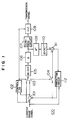
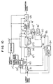
- a conventional high efficiency coding system 100 for an image signal which can remove the time-wise and spatial redundancies, is shown in Fig. 1.
- a subtractor 101 generates a prediction error signal by calculating the difference between a current image signal and a prediction image signal.
- a controller 102 is supplied with the current image signal for one of a plurality of blocks and the prediction image signal to compare their power amounts, and generates a mode signal in accordance with the comparison result.
- the mode signal indicates an intra mode or an inter mode.
- a switch 103 operates in response to the mode signal, i.e., selects, as a signal to be processed, the current image signal in the intra mode and the prediction error signal in the inter mode and outputs the selected signal to a circuit 105 for two-dimensional discrete cosine transform (2D-DCT).
- the circuit 105 executes 2D-DCT processing to the signal to be processed to generate transform coefficients.
- the transform coefficients are quantized by a circuit (Q) 106.
- the quantization coefficients are supplied to a scanning circuit 107 and a dequantization circuit (Q ⁇ 1) 109.
- the quantization coefficients are scanned by the scanning circuit 107 in a zig-zag manner and read out as a train of coefficients to be supplied to a variable length coding circuit (VLC) 108.
- VLC variable length coding circuit
- the quantization coefficients inversely quantized or dequantized by a circuit 109 go through inverse 2D-DCT processing executed by a circuit 110, whereby a signal to be inputted to the circuit 105 is substantially reproduced.
- the reproduced signal is supplied to an adder 111.
- a switch 104 operates in response to the mode signal such that it opens in the intra mode and closes in the inter mode to supply a signal from a predicting circuit 112 to the adder 111.
- the adder 111 outputs to the predicting circuit 112 the reproduced signal by the circuit 110 as a reproduced previous image signal for the next image signal in the intra mode, while reproduces a previous image signal for the next image signal from the reproduced signal as a prediction error signal and a previous image signal for the current image signal and outputs the previous image signal to the predicting circuit 112 in the inter mode.
- the predicting circuit 112 receives the next image signal, in addition to the reproduced previous image signal for the next image signal, generates a motion compensated signal from both signals, and outputs the motion compensated signal as the prediction image signal to the subtractor 101.
- the conventional high efficiency coding system 100 removes the time-wise and spatial redundancies to some degree.
- the output from the VLC 108 was examined, it was revealed that coding was not so efficiently carried out, or the redundancies were sometimes increased on the contrary.
- the present invention has been made in view of the above circumstance, and according to a first aspect of the present invention, there is provided a method of performing high efficiency coding of an image signal wherein one of two-dimensional orthogonal transform such as two-dimensional discrete cosine transform (2D-DCT) for a current image signal and one-dimensional orthogonal transform such as one-dimensional discrete cosine transform (1D-DCT) for a differential image signal between the current signal and a reproduced image signal is selectively employed.
- two-dimensional orthogonal transform such as two-dimensional discrete cosine transform (2D-DCT) for a current image signal
- one-dimensional orthogonal transform such as one-dimensional discrete cosine transform (1D-DCT) for a differential image signal between the current signal and a reproduced image signal
- a method of performing high efficiency coding of an image signal wherein one of a current image signal and an error signal is selected in accordance with the power amount of the current image signal and the error signal, and one of two-dimensional orthogonal transform such as 2D-DCT, one-dimensional orthogonal transform such as 1D-DCT in the horizontal/vertical direction and no transform is selectively employed, for the selected signal, in accordance with the correlation between pixels in the vertical/horizontal direction of the selected signal.
- a method of performing high efficiency coding of an image signal in which a band division and a method of removing the time-wise and spatial redundancies are combined.
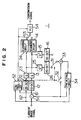
- the coding system 1 includes a subtractor 51; a control section; a processing section including a one-dimensional processing section and a two-dimensional processing section; a variable length coder (VLC) section; and a reproducing section.
- the coding system receives sequentially previous, current and next image signals.
- the subtractor 51 derives a differential image signal, i.e., a prediction error signal, between the inputted current image signal and a reproduced previous image signal for the current image signal.
- a controller 52 in the control section is supplied with the current image signal and the differential image signal to generate a mode signal indicating either one of an inter mode and an intra mode.
- the one-dimensional processing section is supplied with the differential image signal as an objective image signal from the subtractor 51 through a path 61 and performs one-dimensional orthogonal transform processing for the differential image signal to generate a train of quantization coefficients.
- the differential image signal is utilized for generating a transmission signal, this is called the inter mode.
- the two-dimensional processing section is supplied with the current image signal as an objective image signal through a path 62 and performs two-dimensional orthogonal transform processing for the current image signal to generate a train of quantization coefficients.
- the intra mode When the current image signal is utilized as it is for generating a transmission signal.
- the circuit 13 quantizes each transform coefficient from the 1D-DCT 12 with a weight predetermined based on the inter mode and the circuit 23 quantizes each transform coefficient from the 2D-DCT 22 with a predetermined based on the intra mode.
- the circuits 14 and 24 have scanning paths, respectively.
- a switch 53 of the VLC section is responsive to the mode signal from the controller 52 to select one of the trains of quantization coefficients from the one-dimensional and two-dimensional processing sections and supplies the selected train to a variable length coder (VLC) 54 of the VLC section.
- the VLC 54 is also supplied with the mode signal from the controller 52.
- the mode signal is first converted to a code word, and subsequently the selected train of quantization coefficients is converted to code words.
- the mode signal may be converted to the code word after the selected train.
- the converted code words are outputted onto a transmission path as the transmission signal.
- the reproducing section receives quantization coefficients from both of the one-dimensional and two-dimensional processing sections, reproduces the previous image signal for the current image signal and supplies the same to the subtractor 51.
- the one-dimensional processing section includes a one-dimensional discrete cosine transform (1D-DCT) circuit 12; a quantizing circuit (Q) 13 and a scanning circuit 14.
- the 1D-DCT circuit 12 is supplied with a differential image signal, i.e., a prediction error signal for a predetermined size, e.g., a block of 8x8 pixels, and executes 1D-DCT processing as the one-dimensional orthogonal transform processing for the differential image signal per sub-block of eight pixels in the horizontal direction to generate transform coefficients.
- the horizontal direction refers to the scanning line direction in this example.
- the Q 13 quantizes the transform coefficients from the 1D-DCT circuit 12 with respective predetermined weight factors to generate 64 quantization coefficients for eight sub-blocks.
- the scanning circuit 14 scans the quantization coefficients of a one block, i.e., eight sub-blocks arranged in the vertical direction in a predetermined order to generate a train of quantization coefficients.
- the two-dimensional processing section includes a two-dimensional discrete cosine transform (2D-DCT) circuit 22, a quantizing circuit (Q) 23 and a scanning circuit 24.
- the 2D-DCT circuit 22 is supplied with the current image signal for a block of predetermined size, e.g., of 8x8 pixels, directly executes 2D-DCT processing as the two-dimensional orthogonal transform processing for that block to generate transform coefficients.
- the Q 23 quantizes the transform coefficients from the 2D-DCT circuit 22 with respective predetermined weight factors to generate 64 quantization coefficients.
- the scanning circuit 24 scans the 64 quantization coefficients in a predetermined order to generate a train of quantization coefficients.
- the reproducing section includes the dequantizing circuits (Q ⁇ 1) 15 and 25; an inverse two-dimensional discrete cosine transform (2D-DCT ⁇ 1) circuit 26; an inverse one-dimensional discrete cosine transform (1D-DCT ⁇ 1) circuit 16; switches 31 and 32; an adder 33; and a predicting circuit 34.
- the Q ⁇ 1's 15 and 25 respectively dequantizes the quantization coefficients from the Q's 13 and 23 to signals before the quantization.
- the 1D-DCT ⁇ 1 circuit 16 and the 2D-DCT ⁇ 1 circuit 26 respectively execute 1D-DCT ⁇ 1 processing and 2D-DCT ⁇ 1 processing for the signals from Q -1' s 15 and 25 to reproduce the objective image signals.
- the switches 31 and 32 operate in response to the mode signal from the controller 52.
- the switch 31 connects the adder 33 to the circuit 26 in the intra mode and to the circuit 16 in the inter mode.
- the switch 32 is opened in the intra mode and closed in the inter mode.
- the adder 33 adds the inversely transformed signal inputted from the circuit 16 or 26 through the switch 31 to a signal inputted from the predicting circuit 34 through the switch 32 to reproduce a signal.
- the reproduced signal is substantially equal to the inputted current image signal, however, strictly speaking, quantization processing errors may cause inequality between them.
- the reproduced signal is supplied to the predicting circuit 34.
- the predicting circuit 34 is also supplied with the current image signal and executes inter-field prediction/inter-frame prediction/motion compensation prediction.
- the predicting circuit 34 generates a prediction image signal obtained through the inter-field prediction/inter-frame prediction/motion compensation prediction and supplies this signal to the subtractor 51.
- the spatial power spectrum of a prediction error signal will be considered.
- Shishikui entitled “A study on Modelling of Motion Compensated Prediction Error” (The institute of electronics, information and communication engineers, IE 91-35, pp 13-20, July 26, 1991)
- the spatial property of a motion compensated prediction error signal which is largely different from the property of a first-order Marcov model which is used as a model of an image signal, has the following features:
- the correlation between pixels in the horizontal direction is large but that in the vertical direction is small, with respect to the motion compensated prediction error signal in the interlace scanning. For this reason, even if the DCT processing is performed in the vertical direction, few redundancy can be efficiently removed due to the small correlation between pixels. In some cases, the DCT processing may result in increasing the redundancy on the contrary or inducing some artifact distinctive of DCT on the reproduced image. On the other hand, since the correlation between pixels is high in the horizontal direction, the DCT processing is worth executing. Therefore, in this embodiment of the present invention, a prediction error signal is subjected to horizontal 1D-DCT.
- Figs. 2 to 4C the operation of the high efficiency coding system 1 will be explained with reference to Figs. 2 to 4C.
- an image signal including previous, current and next image signals is inputted to the system 1 in frame units or field units.
- one field/frame of image signal has a plurality of blocks, each of which is composed of 8x8 pixels.
- One block of an inputted current image signal is supplied to the subtractor 51 and the controller 52.
- the controller 52 is also supplied with one block of a prediction error signal from the subtractor 51.
- the controller 52 compares the block of the current image signal with that of the prediction error signal, with respect to, for example, a power amount, and generates a mode signal indicating either one of an intra mode and an inter mode so as to improve the coding efficiency.
- Figs. 3A and 3B illustrate the spatial power spectra of the current image signal and the prediction error signal, respectively. It can be seen that the power of the current image signal is concentrated onto the low frequency components of both the horizontal direction ( ⁇ s represents a horizontal sampling frequency) and the vertical direction ( ⁇ s represents a vertical sampling frequency). As to the prediction error signal, while a power concentration onto low frequency components is theoretically seen in the horizontal direction, such power concentration as in the current image signal is not present in the vertical direction.
- intra mode There are two modes: intra mode and inter mode.
- intra mode the 2D-DCT processing is performed and in the inter mode the horizontal 1D-DCT (1H-DCT) processing is performed in which the DCT processing is not performed in the vertical direction since the correlation is small in the vertical.
- 1H-DCT horizontal 1D-DCT
- an image signal goes through the 2D-DCT processing in block or 8x8 pixel units by the 2D-DCT circuit 22 of the two-dimensional processing section to generate transform coefficients, as shown in Fig. 4B.
- the quantizer (Q) 23 quantizes each transform coefficient with a predetermined weight to generate 64 quantization coefficients. The weight is previously determined based on the horizontal and vertical frequencies of the transform coefficient.
- the scanning circuit 24 reads the thus generated 64 quantization coefficients in the order conforming to a scanning path in a zigzag manner shown in Fig. 8A, for example, to generate a train of quantization coefficients.
- a current block of a image signal is divided into eight 8x1 pixels sub-blocks in vertical direction, each of which goes through the 1D-DCT processing by the 1D-DCT circuit 12 to generate 64 transform coefficients for the whole block.
- the quantizer (Q) 13 similar to the circuit 23, quantizes the transform coefficients for each sub-block with corresponding weights to generate eight quantization coefficients.
- the scanning circuit 14 reads the generated 64 quantization coefficients in the order conforming to a scanning path in the vertical direction, as shown in Fig. 4C, for example, to generate a train of quantization coefficients. In the scanning path shown in Fig.
- the horizontal frequency becomes higher from the coefficient at the upper left position toward the right while the vertical frequency becomes higher from the same coefficient toward the downward direction.
- the horizontal frequency becomes higher from the coefficient at the left end toward the right.
- Quantization coefficients in an upper left portion is important in the 2D-DCT processing, while those in a left end portion is important in the 1D-DCT processing. Therefore, the weights applied to a lower right portion are set to be light in the 2D-DCT processing, and the weight applied to a right end portion is set to be light in the 1D-DCT processing. This processing allows quantization coefficients with light weights applied to be compressed efficiently. As a result, the quantization coefficients are read sequentially through the scanning path in the order of importance.
- the switches 31 and 53 connect the circuits 33 and 54 to the circuit 26 and 24, respectively, and the switch 32 is opened.
- the switches 31 and 53 connect the circuits 33 and 54 to the circuits 16 and 14, respectively.
- the switch 32 is closed.
- the quantization coefficient train is supplied to the VLC 54 from the circuit 24 in the intra mode or from the circuit 14 from the inter mode.
- the mode signal is also supplied to the VLC 54.
- the VLC 54 converts the mode signal to a code word, thereby informing with which processing method a block was transformed. Subsequently, a code word is assigned to each coefficient in the quantization coefficient train.
- the mode signal may be encoded following the train.
- a single code word may be assigned to the number of coefficients of zero, thereby improving the compression ratio.
- the generated code words are transmitted through a transmission medium as a transmission signal.
- the quantization coefficients from the Q 23 are subjected to dequantization processing by the Q ⁇ 1 25 and inverse 2D-DCT processing by the circuit 26 to reproduce a signal block substantially equal to the current block of the current image signal supplied to the circuit 22.
- the quantization coefficients from the Q 13 are subjected to dequantization processing by the Q ⁇ 1 15 and inverse 1D-DCT processing by the circuit 16 to reproduce a signal block substantially equal to the current block of the prediction error signal supplied to the circuit 12. Since any signal is not supplied to the adder 33 through the switch 32 in the intra mode, the reproduced signal block is stored through the adder 33 into the predicting circuit 34 as a previous image signal block for the next image signal.
- the adder 33 is supplied with the reproduced signal block from the circuit 16 through the switch 31 and a signal from the predicting circuit 34 through the switch 32 and adds both signals.
- the added signal is stored in the predicting circuit 34 as a previous image signal block for the next image signal.
- the predicting circuit 34 is supplied with the current image signal, performs, for example, a motion compensation prediction with the previous image signal, and supplies the prediction result to the subtractor 51 as a prediction signal, thereby making it possible to perform the above described processing to the next frame/field of the next image signal.
- a current image signal may occasionally have a high level high frequency component in the vertical direction while a prediction error signal may present a low level high frequency component in the vertical direction.
- this example performs one-dimensional orthogonal transform processing or two-dimensional orthogonal transform processing based on the correlation between pixels in the vertical direction for one of a current image signal and a prediction error signal, specified as an objective image signal subjected to the processing.
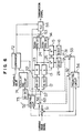
- a high efficiency coding system according to this example will hereinafter be described, where the basic configuration is similar to that shown in Fig. 2 so that different points alone will be explained.
- a controller 52' though similar to the controller 52 shown in Fig. 2, does not supply a mode signal to switches 31 and 53 but to switches 32 and 56 and the quantizing circuits 13 and 23.
- the switch 56 responsive to the mode signal, selects one of the current image signal and prediction error signal as the objective image signal, and supplies the selected one to a switch 57 through a path 63.
- the system shown in Fig. 5 is additionally provided with a sub-control section.
- This sub-control section includes a correlation calculating circuit 71 and a comparator 72.
- the correlation calculating circuit 71 calculates the correlation between pixels in the vertical direction of the objective image signal.
- the comparator 72 compares the calculation result of the circuit 71 with a threshold value to generate a signal indicative of a sub-mode.
- the sub-mode includes a one-dimensional sub-mode and a two-dimensional sub-mode.
- the sub-mode signal is supplied to the switch 57. It is also supplied to the switches 31 and 53 in place of the mode signal in Fig. 2.
- the switch 57 in response to the sub-mode signal, selectively supplies the objective image signal to a one-dimensional processing section or a two-dimensional processing section.
- Each of the quantizing circuits 13 and 23 uses a different weight set in response to the mode signal. That is, the weight set in the inter mode is different from that in the intra mode.
- the circuits 15 and 25 are also changed in correspondence with the circuits 13 and 23.
- a quantization coefficient train generated by a selected processing section is supplied to the VLC 54 through the switch 53 to generate a transmission signal.
- the VLC 54 is also supplied, in addition to the quantization coefficient train, with the mode signal and the sub-mode signal which have been coded prior to the coding of the quantization coefficients train.
- the switch 31, under the control of the sub-mode signal, supplies the adder 33 with a reproduced signal from the circuit 16 in the one-dimensional sub-mode or from the circuit 26 in the two-dimensional sub-mode.
- the switch 32 is controlled by the mode signal so as to be opened in the intra mode and closed in the inter mode.
- Fig. 6 illustrates a modified example of the high efficiency coding system shown in Fig. 5.
- the sub-control section includes a two-dimensional discrete cosine transform (2D-DCT) circuit 73, a calculating circuit 74 and a comparator 72.
- the circuit 73 performs 2D-DCT processing for an objective image signal to generate coefficients.
- Each generated coefficient is squared by the calculating circuit 74.
- the squared coefficients are grouped into a high frequency component and a low frequency component in the vertical direction and accumulated to calculate a ratio of an accumulated value for the low frequency component to an accumulated value for the high frequency component.
- the derived ratio is supplied to the comparator 72 to be compared with a threshold value.
- a sub-mode signal is generated based on the comparison result.
- the rest of the operation of this system is similar to that of the system shown in Fig. 5, so that explanation thereof will be omitted.
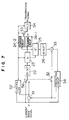
- Fig. 7 illustrates another example of the high efficiency coding system according to the present invention.
- different scanning paths are employed for coding a current image signal and for coding a prediction error signal.
- Explanation given below is directed to different points as compared with the high efficiency coding system shown in Fig. 2.
- a processing section is not provided with a one-dimensional processing section but only with a two-dimensional processing section.
- One of a current image signal and a prediction error signal is selectively supplied to the processing section.
- the two-dimensional processing section is supplied with the current image signal when the intra mode is set by the controller 52 and with a prediction error signal when the inter mode is set by the same.
- the two-dimensional processing section includes two scanning circuits 24-1 and 24-2 in each of which a different scanning path is defined.
- the quantizing circuit 23 has two weight sets for the intra and inter modes, respectively. Thus, the Q ⁇ 1 has inverse numbers of weights of the circuit 23.
- the circuit 23 selects one of the two weight sets in response to the mode signal.
- the switch 53 is controlled by a mode signal from the controller 52 to supply the VLC 54 with a quantization coefficient train from the circuit 24-2 in the intra mode or a quantization coefficient train from the circuit 24-1 in the inter mode.
- the circuit 24-2 reads the quantization coefficient train conforming to the scanning path in a zigzag manner shown in Fig. 8A.
- the circuit 24-1 reads the quantization coefficient train conforming to a scanning path which attaches importance to the vertical direction, as shown in Fig. 8B. This is because the current image signal has power concentrated relatively on a low frequency region as shown in Fig. 3A while power of the prediction error signal is not concentrated on a low frequency region in the vertical direction but entirely distributed.
- a high efficiency coding system for an image signal shown in Fig. 9 is an example which employs a different coding system to each frequency component.
- An input signal is separated into two frequency components, i.e., a horizontal high frequency component and a horizontal low frequency component by a horizontal low pass filter (H-LPF) 90-1 and a horizontal high pass filter (H-HPF) 90-2.
- the horizontal high frequency component and the horizontal low frequency component are further separated into a vertical high frequency component and a vertical low frequency component by vertical low pass filters (H-LPF) 92-1, 92-3 and vertical high pass filters (H-HPF) 92-2, 92-4.
- H-LPF horizontal low pass filter
- H-HPF horizontal high pass filter
- an input signal is separated into four components, i.e., a horizontal high frequency and vertical high frequency component HH; a horizontal high frequency and vertical low frequency component HL; a horizontal low frequency and vertical high frequency component LH; and a horizontal low frequency and vertical low frequency component LL.
- the input signal may be separated in another manner.
- the frequency components HH and HL are directly quantized respectively by quantizers 80-1 and 80-2 with respective predetermined weights, without being subjected to orthogonal transform and coded by VLCs 54-3 and 54-4, respectively.
- the frequency components LH are coded by utilizing motion compensation prediction and horizontal one-dimensional orthogonal transform. In other words, in the coding system shown in Fig. 5, a portion associated with the one-dimensional sub-mode is employed.
- a portion of Fig. 5 includes the subtractor 51-1, the controller 52-1; the switches 56-1 and 32-1; the one-dimensional discrete cosine transform (1D-DCT) circuit 12; the quantizer (Q) 13; the scanning circuit 14; the VLC 54-1; the dequantization processing circuit (Q ⁇ 1) 15; the inverse 1D-DCT processing (1D-DCT ⁇ 1) circuit 16; the adder 33-1; and the predicting circuit 34-1.
- the operations of these components will be readily understood by those skilled in the art from the operation of the coding system shown in Fig. 5.
- Frequency components LL is coded by utilizing motion compensation prediction and two-dimensional orthogonal transform.
- a portion associated with the two-dimensional sub-mode is employed in the coding system shown in Fig. 5. More specifically, a corresponding portion of Fig. 5 includes the subtractor 51-2; the controller 52-2; the switches 56-2 and 32-2; the two-dimensional discrete cosine transform (2D-DCT) circuit 22; the quantizer (Q) 23; the scanning circuit 24; the VLC 54-2; the dequantization processing circuit (Q ⁇ 1) 25; the inverse 2D-DCT processing (2D-DCT ⁇ 1) circuit 26; the adder 33-2; and the predicting circuit 34-2.
- the operations of these components will be readily understood by those skilled in the art from the operation of the coding system shown in Fig. 5. Code words from VLCs 54-1 to 54-4 are multiplexed by a MUX in the previously determined order and outputted to a transmission medium as a transmission signal.
- the controller 52' generates a mode signal indicating either one of the intra mode and the inter mode and supplies the same to the switch 56, the quantizing circuit 13', the dequantizing circuit 15', and the scanning circuit 14'.
- the correlation calculating circuit 71' receives the objective image signal and calculates correlations between pixels in horizontal and vertical directions to supply the calculated results to the comparator 72'.
- the comparator 72' receives two threshold values for horizontal and vertical directions which are compared with outputs from the circuit 71' and generates a sub-mode signal indicating either one of a two-dimensional sub-mode, a one-dimensional horizontal sub-mode, a one-dimensional vertical sub-mode and a zero-dimensional sub-mode.
- the sub-mode signal is supplied to switches 58, 59 and 60, and the quantizing circuit 13', the dequantizing circuit 15', the inverse processing circuit of the DCT 16' and the scanning circuit 14'.
- the current image signal and the prediction image signal from the subtractor 51 are supplied to the switch 56 to output one of them as the objective image signal to the processing section.
- the processing section includes a circuit 12'-1 for one-dimensional orthogonal transform such as the DCT in the horizontal direction, a circuit 12'-2 for one-dimensional orthogonal transform such as the DCT in the vertical direction and switches 58 and 59.
- the processing section can be realized by use of a device similar to the TMC2311 from TRW LSI Products Inc.
- the circuit (1H-DCT) 12'-1 is disposed between the switches 56 and 58 and the circuit (1V-DCT) 12'-2 is disposed between the switches 58 and 59.
- the switches operates in response to the sub-mode signal such that: the objective image signal is transformed by the circuits 12'-1 and 12'-2 in the two-dimensional sub-mode, it is transformed by the circuit 12'-1 with the circuit 12'-2 by-passed in the one-dimensional horizontal sub-mode, it is transformed by the circuit 12'-2 with the circuit 12'-1 by-passed in the one-dimensional vertical sub-mode, and it is not transformed with the circuits 12'-1 and 12'-2 by-passed in the zero-dimensional sub-mode.
- the quantizing circuit 13' has eight weight sets for eight modes determined by the mode signal and the sub-mode signal.
- the dequantizing circuit 15' is disposed in correspondence with the circuit 13'. Also, the scanning circuit 14' has eight scanning paths for the eight modes.
- the output from the circuit 14' is encoded by the VLC 54 together with the mode signal and the sub-mode signal to be transmitted onto the transfer media as the transmission signal.
- the switch 60 connects the adder 33 to the dequantizing circuit 15' in the zero-dimensional sub-mode and to the circuit 16' in the other sub-modes. The remaining portion of the reproducing section is similar to that shown in Fig. 5.
Landscapes
- Engineering & Computer Science (AREA)
- Multimedia (AREA)
- Signal Processing (AREA)
- Physics & Mathematics (AREA)
- Discrete Mathematics (AREA)
- General Physics & Mathematics (AREA)
- Compression Or Coding Systems Of Tv Signals (AREA)
Applications Claiming Priority (6)
| Application Number | Priority Date | Filing Date | Title |
|---|---|---|---|
| JP29560291A JP3069174B2 (ja) | 1991-11-12 | 1991-11-12 | モード適応符号化装置 |
| JP295602/91 | 1991-11-12 | ||
| JP01211892A JP3361543B2 (ja) | 1992-01-27 | 1992-01-27 | 画像信号符号化装置 |
| JP12118/92 | 1992-01-27 | ||
| JP25673992A JPH06113281A (ja) | 1992-09-25 | 1992-09-25 | サブバンド・変換符号化方式 |
| JP256739/92 | 1992-09-25 |
Publications (3)
| Publication Number | Publication Date |
|---|---|
| EP0542261A2 true EP0542261A2 (de) | 1993-05-19 |
| EP0542261A3 EP0542261A3 (de) | 1994-01-26 |
| EP0542261B1 EP0542261B1 (de) | 1998-10-21 |
Family
ID=27279712
Family Applications (1)
| Application Number | Title | Priority Date | Filing Date |
|---|---|---|---|
| EP92119363A Expired - Lifetime EP0542261B1 (de) | 1991-11-12 | 1992-11-12 | Verfahren und System für die Ausführung einer hochwirksamen Bildsignalkodierung |
Country Status (3)
| Country | Link |
|---|---|
| US (1) | US5534927A (de) |
| EP (1) | EP0542261B1 (de) |
| DE (1) | DE69227352T2 (de) |
Cited By (5)
| Publication number | Priority date | Publication date | Assignee | Title |
|---|---|---|---|---|
| EP0586225A2 (de) * | 1992-08-31 | 1994-03-09 | Victor Company Of Japan, Ltd. | Vorrichtung zur orthogonalen Transformationskodierung und -dekodierung |
| EP0614318A2 (de) * | 1993-03-04 | 1994-09-07 | Kabushiki Kaisha Toshiba | Videokoder, Videodekoder, und Vorrichtung zur Videobewegungsschätzung |
| EP0620687A2 (de) * | 1993-04-13 | 1994-10-19 | Samsung Electronics Co., Ltd. | Kodierungsvorrichtung und -verfahren |
| EP0649261A2 (de) * | 1993-10-18 | 1995-04-19 | Canon Kabushiki Kaisha | Vorrichtung zur Verarbeitung und Verschlüsselung von Bilddaten |
| CN112584158A (zh) * | 2019-09-30 | 2021-03-30 | 复旦大学 | 视频质量增强方法和系统 |
Families Citing this family (27)
| Publication number | Priority date | Publication date | Assignee | Title |
|---|---|---|---|---|
| US5767911A (en) | 1994-12-20 | 1998-06-16 | Matsushita Electric Industrial Co., Ltd. | Object-based digital image predictive coding transfer method and apparatus, and decoding apparatus |
| JP3700195B2 (ja) * | 1995-01-10 | 2005-09-28 | ソニー株式会社 | 復号化装置、再生装置、記録再生装置、画像処理システム、復号化方法、再生方法、記録再生方法及び画像処理方法 |
| DE69619002T2 (de) | 1995-03-10 | 2002-11-21 | Toshiba Kawasaki Kk | Bildkodierungs-/-dekodierungsvorrichtung |
| US5936673A (en) | 1995-05-26 | 1999-08-10 | Intel Corporation | Temporal tile staggering for block based video compression |
| GB2305797B (en) * | 1995-09-27 | 2000-03-01 | Sony Uk Ltd | Video data compression |
| AU1941797A (en) * | 1997-03-17 | 1998-10-12 | Mitsubishi Denki Kabushiki Kaisha | Image encoder, image decoder, image encoding method, image decoding method and image encoding/decoding system |
| JP3570863B2 (ja) * | 1997-08-05 | 2004-09-29 | 三菱電機株式会社 | 動画像復号化装置および動画像復号化方法 |
| CN1278385A (zh) * | 1997-10-28 | 2000-12-27 | 西门子公司 | 数字化图象的处理方法和装置 |
| US6094225A (en) * | 1997-12-02 | 2000-07-25 | Daewoo Electronics, Co., Ltd. | Method and apparatus for encoding mode signals for use in a binary shape coder |
| EP0921497B1 (de) * | 1997-12-02 | 2004-03-24 | Daewoo Electronics Corporation | Gerät zur Kodierung binärer Figuren im Zeilensprungformat |
| US6748118B1 (en) * | 2000-02-18 | 2004-06-08 | Intel Corporation | Method of quantizing signal samples of an image during same |
| US6961472B1 (en) * | 2000-02-18 | 2005-11-01 | Intel Corporation | Method of inverse quantized signal samples of an image during image decompression |
| JP2001298746A (ja) * | 2000-03-09 | 2001-10-26 | Samsung Techwin Co Ltd | デジタル記録システムのデータ圧縮装置及びその制御方法 |
| US20030099294A1 (en) * | 2001-11-27 | 2003-05-29 | Limin Wang | Picture level adaptive frame/field coding for digital video content |
| US7162094B2 (en) * | 2001-11-27 | 2007-01-09 | General Instrument Corporation | Frequency coefficient scanning paths for coding digital video content |
| JP4447197B2 (ja) * | 2002-01-07 | 2010-04-07 | 三菱電機株式会社 | 動画像符号化装置および動画像復号装置 |
| US20040125204A1 (en) * | 2002-12-27 | 2004-07-01 | Yoshihisa Yamada | Moving picture coding apparatus and moving picture decoding apparatus |
| US7065465B2 (en) * | 2002-03-26 | 2006-06-20 | Lockheed Martin Corporation | Method and system for multi-sensor data fusion |
| FR2840147B1 (fr) * | 2002-05-24 | 2004-08-27 | France Telecom | Procedes de brouillage et de debrouillage de signal video, systeme, decodeur, serveur de diffusion, support de donnees pour la mise en oeuvre de ces procedes |
| US7653255B2 (en) | 2004-06-02 | 2010-01-26 | Adobe Systems Incorporated | Image region of interest encoding |
| US7639886B1 (en) | 2004-10-04 | 2009-12-29 | Adobe Systems Incorporated | Determining scalar quantizers for a signal based on a target distortion |
| US7522220B2 (en) * | 2005-03-30 | 2009-04-21 | Samsung Electronics Co., Ltd. | Dual-channel adaptive 2D noise reduction for video signals |
| KR100750145B1 (ko) * | 2005-12-12 | 2007-08-21 | 삼성전자주식회사 | 영상의 인트라 예측 부호화, 복호화 방법 및 장치 |
| JP4643437B2 (ja) * | 2005-12-27 | 2011-03-02 | 株式会社東芝 | 情報処理装置 |
| JP4643453B2 (ja) * | 2006-01-10 | 2011-03-02 | 株式会社東芝 | 情報処理装置及び情報処理装置の動画像復号方法 |
| JP2009240284A (ja) | 2008-03-31 | 2009-10-22 | Fujifilm Corp | プロテアーゼ検出材料、プロテアーゼ検出材料セット、及びプロテアーゼ測定方法 |
| GB2492333B (en) * | 2011-06-27 | 2018-12-12 | British Broadcasting Corp | Video encoding and decoding using transforms |
Citations (1)
| Publication number | Priority date | Publication date | Assignee | Title |
|---|---|---|---|---|
| EP0250152A2 (de) * | 1986-06-19 | 1987-12-23 | AT&T Corp. | Sehr schnelle Transformationsvorrichtung |
Family Cites Families (13)
| Publication number | Priority date | Publication date | Assignee | Title |
|---|---|---|---|---|
| EP0290085B1 (de) * | 1987-05-06 | 1996-03-20 | Philips Patentverwaltung GmbH | System zur Übertragung von Videobildern |
| US4821119A (en) * | 1988-05-04 | 1989-04-11 | Bell Communications Research, Inc. | Method and apparatus for low bit-rate interframe video coding |
| US4829378A (en) * | 1988-06-09 | 1989-05-09 | Bell Communications Research, Inc. | Sub-band coding of images with low computational complexity |
| US5057918A (en) * | 1989-09-15 | 1991-10-15 | U.S. Philips Corporation | Arrangement for encoding two-dimensional information, grouped in periodical information clusters using motion vector processing in a hybrid DPCM encoder |
| US4969040A (en) * | 1989-10-26 | 1990-11-06 | Bell Communications Research, Inc. | Apparatus and method for differential sub-band coding of video signals |
| JPH0714209B2 (ja) * | 1989-12-20 | 1995-02-15 | 松下電器産業株式会社 | 動画像符号化装置 |
| DK0441168T3 (da) * | 1990-02-06 | 1996-11-18 | Alcatel Italia | System, pakkestruktur og indretning til at behandle udgående information fra en signalindkoder |
| FR2660139B1 (fr) * | 1990-03-23 | 1995-08-25 | France Etat | Procede de codage et de transmission a au moins deux niveaux de qualite d'images numeriques appartenant a une sequence d'images, et dispositifs correspondants. |
| US5150432A (en) * | 1990-03-26 | 1992-09-22 | Kabushiki Kaisha Toshiba | Apparatus for encoding/decoding video signals to improve quality of a specific region |
| US4999705A (en) * | 1990-05-03 | 1991-03-12 | At&T Bell Laboratories | Three dimensional motion compensated video coding |
| US5068724A (en) * | 1990-06-15 | 1991-11-26 | General Instrument Corporation | Adaptive motion compensation for digital television |
| US5126962A (en) * | 1990-07-11 | 1992-06-30 | Massachusetts Institute Of Technology | Discrete cosine transform processing system |
| JP2864725B2 (ja) * | 1990-11-20 | 1999-03-08 | ソニー株式会社 | 画像信号の高能率符号化装置 |
-
1992
- 1992-11-12 US US07/975,433 patent/US5534927A/en not_active Expired - Lifetime
- 1992-11-12 DE DE69227352T patent/DE69227352T2/de not_active Expired - Fee Related
- 1992-11-12 EP EP92119363A patent/EP0542261B1/de not_active Expired - Lifetime
Patent Citations (1)
| Publication number | Priority date | Publication date | Assignee | Title |
|---|---|---|---|---|
| EP0250152A2 (de) * | 1986-06-19 | 1987-12-23 | AT&T Corp. | Sehr schnelle Transformationsvorrichtung |
Non-Patent Citations (5)
| Title |
|---|
| 7TH HAWAII INTERNATIONAL CONFERENCE ON SYSTEM SCIENCES January 1974 , HAWAII, US pages 10 - 12 ISHII ET AL 'PICTURE BANDWIDTH COMPRESSION BY DPCM IN THE HADAMARD TRANSFORM DOMAIN' * |
| IEEE TRANSACTIONS ON CIRCUITS AND SYSTEMS FOR VIDEO TECHNOLOGY vol. 1, no. 2 , June 1991 , NEW YORK US pages 174 - 183 XP000214520 GHARAVI 'Subband Coding Algorithms for Video Applications: Videophone to HDTV-Conferencing' * |
| IEEE TRANSACTIONS ON ELECTROMAGNETIC COMPATIBILITY vol. 23, no. 2 , May 1981 , NEW YORK US pages 103 - 107 JAIN ET AL 'Real-Time Hadamard Transform Coding for TV Signals' * |
| SLABOPROUDY OBZOR vol. 48, no. 8 , August 1987 , CZ pages 393 - 397 MIHALIK ET AL 'Optimalizacia jednorozmernych hybridnych kodovacich systemov obrazov' * |
| TIJDSCHRIFT VAN HET NEDERLANDS ELEKTRONICA- EN RADIOGENOOTSCHAP vol. 39, no. 5-6 , 1974 pages 169 - 177 DE BROUWER ET AL 'TWEE-DIMENSIONALE BEELD-CODERING DOOR HET KOMBINEREN VAN EEN-DIMENSIONALE HADAMARD TRANSFORMATIE EN DPCM' * |
Cited By (14)
| Publication number | Priority date | Publication date | Assignee | Title |
|---|---|---|---|---|
| US5424778A (en) * | 1992-08-31 | 1995-06-13 | Victor Company Of Japan, Ltd. | Orthogonal transform coding apparatus and decoding apparatus |
| US5502491A (en) * | 1992-08-31 | 1996-03-26 | Victor Company Of Japan, Ltd. | Orthogonal transform coding apparatus and decoding apparatus |
| EP0586225A2 (de) * | 1992-08-31 | 1994-03-09 | Victor Company Of Japan, Ltd. | Vorrichtung zur orthogonalen Transformationskodierung und -dekodierung |
| EP0586225A3 (de) * | 1992-08-31 | 1994-11-02 | Victor Company Of Japan | Vorrichtung zur orthogonalen Transformationskodierung und -dekodierung. |
| EP0614318A3 (de) * | 1993-03-04 | 1995-05-17 | Tokyo Shibaura Electric Co | Videokoder, Videodekoder, und Vorrichtung zur Videobewegungsschätzung. |
| EP0614318A2 (de) * | 1993-03-04 | 1994-09-07 | Kabushiki Kaisha Toshiba | Videokoder, Videodekoder, und Vorrichtung zur Videobewegungsschätzung |
| US5592228A (en) * | 1993-03-04 | 1997-01-07 | Kabushiki Kaisha Toshiba | Video encoder using global motion estimation and polygonal patch motion estimation |
| EP0620687A2 (de) * | 1993-04-13 | 1994-10-19 | Samsung Electronics Co., Ltd. | Kodierungsvorrichtung und -verfahren |
| EP0620687A3 (de) * | 1993-04-13 | 1996-05-15 | Samsung Electronics Co Ltd | Kodierungsvorrichtung und -verfahren. |
| EP0649261A2 (de) * | 1993-10-18 | 1995-04-19 | Canon Kabushiki Kaisha | Vorrichtung zur Verarbeitung und Verschlüsselung von Bilddaten |
| EP0649261A3 (de) * | 1993-10-18 | 1995-06-21 | Canon Kk | Vorrichtung zur Verarbeitung und Verschlüsselung von Bilddaten. |
| US5933499A (en) * | 1993-10-18 | 1999-08-03 | Canon Kabushiki Kaisha | Image processing apparatus |
| US6519341B1 (en) | 1993-10-18 | 2003-02-11 | Canon Kabushiki Kaisha | Method and apparatus for outputting a high definition image |
| CN112584158A (zh) * | 2019-09-30 | 2021-03-30 | 复旦大学 | 视频质量增强方法和系统 |
Also Published As
| Publication number | Publication date |
|---|---|
| DE69227352T2 (de) | 1999-04-15 |
| EP0542261B1 (de) | 1998-10-21 |
| DE69227352D1 (de) | 1998-11-26 |
| US5534927A (en) | 1996-07-09 |
| EP0542261A3 (de) | 1994-01-26 |
Similar Documents
| Publication | Publication Date | Title |
|---|---|---|
| US5534927A (en) | Method of performing high efficiency coding of image signal and system therefor | |
| US6658157B1 (en) | Method and apparatus for converting image information | |
| KR0150955B1 (ko) | 비트고정을 위한 영상압축방법과 신장방법 및 그 장치 | |
| JP3118237B1 (ja) | 画像予測復号化方法 | |
| JP2744871B2 (ja) | 画像信号符号化方法および画像信号符号化装置 | |
| US5440344A (en) | Video encoder using adjacent pixel difference for quantizer control | |
| EP1246131B1 (de) | Verfahren und Vorrichtung zur Reduzierung von Störungen in dekodierten Bildern mit Nachfilterung | |
| EP0831660B1 (de) | Videokodierer mit Transformationskoeffizientenprädiktion | |
| US7221709B2 (en) | Information processing apparatus and method, and program storage medium | |
| US5301032A (en) | Digital image compression and decompression method and apparatus using variable-length coding | |
| JP3025610B2 (ja) | 符号化方法およびその装置 | |
| US20070025447A1 (en) | Noise filter for video compression | |
| US9071844B2 (en) | Motion estimation with motion vector penalty | |
| WO1996036182A1 (en) | Mpeg encoder that concurrently determines video data encoding format and rate control | |
| US20070076803A1 (en) | Dynamic pre-filter control with subjective noise detector for video compression | |
| US5508745A (en) | Apparatus for controlling a quantization level to be modified by a motion vector | |
| US5742346A (en) | Spatially adaptive blur filter | |
| JP3089941B2 (ja) | 画像間予測符号化装置 | |
| KR0157465B1 (ko) | 영상데이타의 영상특성에 따른 양자화레벨결정방법 및 그 장치 | |
| JPH04322593A (ja) | 画像符号化装置及びその復号化装置 | |
| JP3211989B2 (ja) | 直交変換符号化装置及び復号化装置 | |
| KR100223647B1 (ko) | 동영상 압축/복원시스템에서의 효과적인 움직임추정/보상방법및시스템 | |
| JP3343554B1 (ja) | 画像予測復号化方法及び画像予測符号化装置 | |
| JP3403561B2 (ja) | 動画像符号化方法及びその装置 | |
| JP2002359852A (ja) | 画像予測復号化装置及び方法 |
Legal Events
| Date | Code | Title | Description |
|---|---|---|---|
| PUAI | Public reference made under article 153(3) epc to a published international application that has entered the european phase |
Free format text: ORIGINAL CODE: 0009012 |
|
| AK | Designated contracting states |
Kind code of ref document: A2 Designated state(s): DE FR GB |
|
| PUAL | Search report despatched |
Free format text: ORIGINAL CODE: 0009013 |
|
| AK | Designated contracting states |
Kind code of ref document: A3 Designated state(s): DE FR GB |
|
| 17P | Request for examination filed |
Effective date: 19940601 |
|
| 17Q | First examination report despatched |
Effective date: 19960710 |
|
| GRAG | Despatch of communication of intention to grant |
Free format text: ORIGINAL CODE: EPIDOS AGRA |
|
| GRAG | Despatch of communication of intention to grant |
Free format text: ORIGINAL CODE: EPIDOS AGRA |
|
| GRAH | Despatch of communication of intention to grant a patent |
Free format text: ORIGINAL CODE: EPIDOS IGRA |
|
| GRAH | Despatch of communication of intention to grant a patent |
Free format text: ORIGINAL CODE: EPIDOS IGRA |
|
| GRAH | Despatch of communication of intention to grant a patent |
Free format text: ORIGINAL CODE: EPIDOS IGRA |
|
| GRAA | (expected) grant |
Free format text: ORIGINAL CODE: 0009210 |
|
| AK | Designated contracting states |
Kind code of ref document: B1 Designated state(s): DE FR GB |
|
| ET | Fr: translation filed | ||
| REF | Corresponds to: |
Ref document number: 69227352 Country of ref document: DE Date of ref document: 19981126 |
|
| PLBE | No opposition filed within time limit |
Free format text: ORIGINAL CODE: 0009261 |
|
| STAA | Information on the status of an ep patent application or granted ep patent |
Free format text: STATUS: NO OPPOSITION FILED WITHIN TIME LIMIT |
|
| 26N | No opposition filed | ||
| REG | Reference to a national code |
Ref country code: GB Ref legal event code: IF02 |
|
| PGFP | Annual fee paid to national office [announced via postgrant information from national office to epo] |
Ref country code: FR Payment date: 20051108 Year of fee payment: 14 |
|
| PGFP | Annual fee paid to national office [announced via postgrant information from national office to epo] |
Ref country code: GB Payment date: 20051109 Year of fee payment: 14 |
|
| PGFP | Annual fee paid to national office [announced via postgrant information from national office to epo] |
Ref country code: DE Payment date: 20051110 Year of fee payment: 14 |
|
| PG25 | Lapsed in a contracting state [announced via postgrant information from national office to epo] |
Ref country code: DE Free format text: LAPSE BECAUSE OF NON-PAYMENT OF DUE FEES Effective date: 20070601 |
|
| GBPC | Gb: european patent ceased through non-payment of renewal fee |
Effective date: 20061112 |
|
| REG | Reference to a national code |
Ref country code: FR Ref legal event code: ST Effective date: 20070731 |
|
| PG25 | Lapsed in a contracting state [announced via postgrant information from national office to epo] |
Ref country code: GB Free format text: LAPSE BECAUSE OF NON-PAYMENT OF DUE FEES Effective date: 20061112 |
|
| PG25 | Lapsed in a contracting state [announced via postgrant information from national office to epo] |
Ref country code: FR Free format text: LAPSE BECAUSE OF NON-PAYMENT OF DUE FEES Effective date: 20061130 |