EP0542226B1 - Appareil pour séparer et alimenter des papiers et méthode de contrÔle dudit appareil et distributeur automatique de billets fonctionnant selon ladite méthode - Google Patents
Appareil pour séparer et alimenter des papiers et méthode de contrÔle dudit appareil et distributeur automatique de billets fonctionnant selon ladite méthode Download PDFInfo
- Publication number
- EP0542226B1 EP0542226B1 EP19920119287 EP92119287A EP0542226B1 EP 0542226 B1 EP0542226 B1 EP 0542226B1 EP 19920119287 EP19920119287 EP 19920119287 EP 92119287 A EP92119287 A EP 92119287A EP 0542226 B1 EP0542226 B1 EP 0542226B1
- Authority
- EP
- European Patent Office
- Prior art keywords
- feeding
- pinching
- sheets
- length
- rollers
- Prior art date
- Legal status (The legal status is an assumption and is not a legal conclusion. Google has not performed a legal analysis and makes no representation as to the accuracy of the status listed.)
- Expired - Lifetime
Links
- 238000000034 method Methods 0.000 title claims description 9
- 230000001276 controlling effect Effects 0.000 claims description 5
- 238000001514 detection method Methods 0.000 claims description 5
- 230000002079 cooperative effect Effects 0.000 claims 1
- 230000033001 locomotion Effects 0.000 claims 1
- 238000010276 construction Methods 0.000 description 6
- 230000006835 compression Effects 0.000 description 1
- 238000007906 compression Methods 0.000 description 1
- 230000001419 dependent effect Effects 0.000 description 1
- 230000001105 regulatory effect Effects 0.000 description 1
Images

Classifications
-
- B—PERFORMING OPERATIONS; TRANSPORTING
- B65—CONVEYING; PACKING; STORING; HANDLING THIN OR FILAMENTARY MATERIAL
- B65H—HANDLING THIN OR FILAMENTARY MATERIAL, e.g. SHEETS, WEBS, CABLES
- B65H5/00—Feeding articles separated from piles; Feeding articles to machines
- B65H5/06—Feeding articles separated from piles; Feeding articles to machines by rollers or balls, e.g. between rollers
- B65H5/062—Feeding articles separated from piles; Feeding articles to machines by rollers or balls, e.g. between rollers between rollers or balls
-
- B—PERFORMING OPERATIONS; TRANSPORTING
- B65—CONVEYING; PACKING; STORING; HANDLING THIN OR FILAMENTARY MATERIAL
- B65H—HANDLING THIN OR FILAMENTARY MATERIAL, e.g. SHEETS, WEBS, CABLES
- B65H2301/00—Handling processes for sheets or webs
- B65H2301/30—Orientation, displacement, position of the handled material
- B65H2301/32—Orientation of handled material
- B65H2301/321—Standing on edge
-
- B—PERFORMING OPERATIONS; TRANSPORTING
- B65—CONVEYING; PACKING; STORING; HANDLING THIN OR FILAMENTARY MATERIAL
- B65H—HANDLING THIN OR FILAMENTARY MATERIAL, e.g. SHEETS, WEBS, CABLES
- B65H2402/00—Constructional details of the handling apparatus
-
- B—PERFORMING OPERATIONS; TRANSPORTING
- B65—CONVEYING; PACKING; STORING; HANDLING THIN OR FILAMENTARY MATERIAL
- B65H—HANDLING THIN OR FILAMENTARY MATERIAL, e.g. SHEETS, WEBS, CABLES
- B65H2701/00—Handled material; Storage means
- B65H2701/10—Handled articles or webs
- B65H2701/19—Specific article or web
- B65H2701/1912—Banknotes, bills and cheques or the like
Definitions
- the present invention relates to a sheet separating and driving or feeding apparatus according to the preamble of claim 1.
- Such an apparatus is known from FR-A-2 388 353.
- the invention further relates to a method of controlling the apparatus and to an automatic teller using the apparatus and method.
- Apparatuses disclosed, for example, in Japanese Utility Model Unexamined Publication No. 63-71140, Japanese Patent Unexamined Publication No. 59-205694, Japanese Utility Model Unexamined Publication No. 3-28129 and others are known hitherto as a paper separating and feeding apparatus comprising pick-up rollers coming into contact with the outer surface of a paper in a stack to provide a driving force periodically to the papers, feed rollers disposed opposite to each other at positions where the driven papers can be pinched therebetween, gate rollers fixed in the feeding direction of the papers, and operating to separate the paper sheets one by one and to feed them to a pass on the rear stage of the outlet.
- the latter problem may bring about a restriction when a common bill carrying pass is obtained in case a plurality of paper (bill) separating and feeding apparatuses are combined like in an automatic teller.
- EP-A-0 294 055 discloses a paper feeding apparatus for a printer comprising a paper feed roller engageable with a topmost sheet in a stack for separating and feeding the sheets towards a platen. Between the feed roller and the platen an auxiliary feed roller being in contact with a pinch roller is provided for engaging a sheet being fed from the paper feed roller to the platen.
- FR-A-2 388 353 discloses a bill dispenser having a pressure roller and and idling pressure roller arranged with respect to a driving roller.
- the pressure roller and the idling pressure roller are always in contact with the driving roller and the idling pressure roller cannot be controlled in accordance with the length of the conveyed bills.
- the object of the invention is to provide a sheet separating and feeding apparatus, a method of controlling the same and an automatic teller using the apparatus and method which are capable of feeding sheets having a large variation of length in feeding direction.
- a variety of sheets with a length in the feeding direction kept within a predetermined range can be fed sheet by sheet securely at every rotation of the feed rollers and carried to a downstream disposed carrying pass. Further, for stopping a drive of papers, a stop operation will not be retarded more than necessary for papers with a big length in feeding direction, therefore an erroneous driving of ensuing papers will never be occur.
- the degree of freedom of a position of the paper pinching point of the carrying pass can be enlarged, and thus the degree of freedom of the construction will largely be enhanced when utilizing this in an automatic teller.
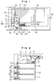
- Fig. 2 is a constructional view of an automatic teller according to one preferred embodiment of the present invention.
- reference characters 1A to 1C denote safes, which are capable of corresponding, as described hereinlater, to bills with the short side length largely varying at all denominations (for example French franc bills having a length at the short side between 50 and 100 mm).
- the safe 1A is packed with bills having a length of 100 mm at the short side
- the safe 1B is packed with bills having a length of 70 mm
- the safe 1C is packed with bills having a length of 50 mm.
- Reference characters 2A to 2C denote separating portions relating to the present invention, and at the time of payment in cash, bills driven from each safe in order by predetermined number are accumulated in an outlet stacker 7 through carrying passes 3A to 3C, 5 and 6 driven by a main motor 4, discharged collectively from an outlet 8 to payment.
- a transfer gate 10 is actuated to allow receiving of such bills into a reject box 12 through a reject carrying pass 11.
- Fig. 1 shows a safe unit having the safe 1A and the bill separating and feeding apparatus 2A in the automatic teller illustrated in Fig. 2.
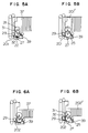
- the bill separating and feeding apparatus 2A comprises pick-up rollers 21 coming in contact with bills 20 to be stacked and having the outer peripheries partly constructed of a friction member 31 each, feed rollers 22 having the same diameter as that of the pick-up rollers 21, and having the outer peripheries constructed partly of a friction member 32 each, gate rollers 23 opposite to the feed rollers 22, energized by a compression spring 24, having the outer peripheries constructed of a friction member each, and regulated to run in the driving direction, and first pinch rollers 25 and second pinch rollers 27 which will be described hereinlater.
- Fig. 3 is a side elevational view of a main part viewed in the direction indicated by an arrow A of Fig. 1, indicating a positional relation of the aforementioned pick-up rollers 21, feed rollers 22, gate rollers 23, first pinch rollers 25, second pinch rollers 27 and each friction member provided thereon. Then, Fig. 3 and Fig. 4 indicate a relative positional relation particularly of the feed roller 22, the gate roller 23 and the first pinch roller 25.
- the gate roller 23 is brought into contact with the feed roller 22 on one side where its outer periphery is constructed partly of the friction member 32, and the first pinch roller 25 is brought into contact with the feed roller 22 on another side where its outer periphery is constructed entirely of the friction member 32, thus constructing first pinching and carrying or feeding means.
- the first pinch roller 25 is brought into contact with the feed roller 22 on the side where its outer periphery is constructed entirely of the friction member 32, and is energized by a spring 26 toward the feed roller 22.
- the aforementioned second pinch roller 27 is rotatable about a supporting point 33 serving as a center of rotation, and supported rotatably supported on a lever 28 energized by a spring 34 in clockwise direction in the illustration, and is pushed toward the feed roller 22. That is, the second pinch roller 27 functions as a second pinching and carrying or feeding means, and when the lever 28 is turned counterclockwise in the illustration against the spring 34, it comes away from the feed roller 22, but when the force is removed it is pushed towards the feed roller 22.
- reference characters 9A, 9B, 9C denote driving motors for the safes 1A, 1B, 1C respectively
- a reference numeral 29 denotes a bill pinching start point of the carrying pass 3A
- 35 denotes a bill push plate of the safe 1A
- the push plate 35 pushes the bills 20 to the feed rollers 22 through a spring 36.
- a reference numeral 37 denotes a guide member corresponding to a size (short side length) of the bills 20 in the safe 1A, and as will be described hereinlater, the operation of the lever 28 is controlled by the guide member 37.
- reference numeral 38 indicates the direction in which the safes are moved
- 39 denotes a passage detection sensor for detecting the bills having passed a pinching point of the feed roller 22 and the first pinch roller 25.
- the aforementioned lever 28, spring 34, guide member 37 and other construct an identification part of the length of the bills 20 along the feeding direction, and as will be described hereinlater, the second pinch rollers 27 according to the length of the bills 20 are actuated thereby.
- the safe 1A is constructed to be detachable in the direction indicated by the arrow 38, and the gate rollers 23 and the first pinch rollers 25 are mounted on a lower portion of the safe 1A. That is, the construction is such that the gate rollers 23 and the first pinch rollers 25 are pressed to the feed rollers 22 provided on an apparatus body side by setting the safe 1A on the apparatus body of the present embodiment.
- the construction is such that in case the bills have a length of not less than 75 mm at the short side and the safe 1A is installed, the guide member 37 thrusts the lever 28 on its nose, and detaches the second pinch rollers 27 from the feed rollers 22 to release pinching.
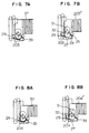
- Figs. 5A and 5B illustrate an operation when the apparatus according to the invention handles the longest bills 201, with a length of 100 mm
- Figs. 6A and 6B illustrate an operation when the apparatus handles the shortest bills 202, with a length of 50 mm
- Figs. 7A and 7B illustrates an operation when bills 203 with a length of 75 mm are handled
- Figs. 8A and 8B illustrate an operation when bills 204 with a length of 70 mm are handled.
- Figs. 5A to 8B Fig. 5A, Fig. 6A, Fig. 7A and Fig. 8A indicate a condition midway of driving
- Fig. 5B, Fig. 6B, Fig. 7B and Fig. 8B indicate a condition when driving is stopped.
- a size and an arrangement of the rollers will be taken up for description. Since one sheet of bill is fed per rotation, the feed rollers 22 and the pick-up roller 21 are 40 mm in diameter so as to have the outer periphery longer than a maximum bill length. Further, a distance from the first pinch roller 25 to the bill pinching start point 29 of the carrying pass 3A is about 70 mm so as to handle the bills 201, 203 not less than 75 mm in length in the state where a pinching force of the second pinch rollers 27 is not working. A distance from the second pinch roller 27 to the pinching start point 29 of the carrying pass 3A is about 45 mm so as to handle the shortest bills 202, with a length of 50 mm.
- Described next is an operation controlling method when the driving operation comes to stop at a predetermined number of sheets to drive after the operation is started.
- a general operation is such that the feed rollers 22 and the pick-up rollers 21 are driven to rotate by the motor 9A, the bills separated and fed sheet by sheet are pinched and carried on the feed rollers 22 and the first pinch rollers 25 only or the second pinch rollers 27 together, and are delivered to the carrying pass 3A at the pinching start point 29.
- Figs. 8A and 8B when handling the bills 202, 204 below 75 mm in length, since the pinching force of the second pinch rollers 27 is ready for working, as described hereinbefore, the number of passing bills is counted on the passage detection sensor 39, and after the time required for rear ends of the bills to pass the pinching point of the second pinch rollers 27 passes from the point in time when passage of the rear ends of the predetermined final bills 201, 203 is detected, the motor 9A is shut down. In this case, an operation for driving the ensuing bills 201', 203' will also not be started.
- one sheet of the bill can securely be driven per rotation of the feed rollers and carried to the carrying pass 3A in case every bills are handled.
- the second pinch rollers 27 can be disposed according to the length of bills, therefore a stop operation for the long bills will not be retarded more than necessary, and the possibility of the ensuing bills being driven can be minimized.
- the above-described embodiment is only to exemplify the present invention, and hence the invention is not necessary limited, needless to say, to the embodiment.
- the invention may be applied not only to the automatic teller but also extensively to other general paper handling apparatuses.
- the identification part comprising lever, guide member and others will be provided to come on a lower side of papers, and may function to control the second paper carrying means according to the length of papers in the feeding direction.
- an advantage inherent therein is that such a paper separating and feeding apparatus is capable of separating and feeding securely even such papers varying largely in length, and also disposing a paper pinching point of a downstream disposed carrying pass with a large degree of freedom, and its controlling method can be realized.
Landscapes
- Engineering & Computer Science (AREA)
- Mechanical Engineering (AREA)
- Sheets, Magazines, And Separation Thereof (AREA)
- Delivering By Means Of Belts And Rollers (AREA)
- Controlling Sheets Or Webs (AREA)
Claims (7)
- Dispositif pour séparer et acheminer des feuilles, comprenant:- des galets preneurs (21) pour séparer des feuilles empilées,- des galets d'acheminement (22) et des galets de délivrance (23) pour séparer et acheminer les feuilles entraînées par lesdits galets preneurs (21), feuille après feuille, de par la coopération desdits galets d'acheminement (22) avec lesdits galets de délivrance (23),- un premier moyen de pincement et d'acheminement (25) au voisinage du point de pincement desdits galets de délivrance (23) et desdits galets d'acheminement (22), placé au contact desdits galets d'acheminement (22) et entraîné a la même vitesse circonférentielle que lesdits galets d'acheminement (22) pour pincer et acheminer les feuilles jusqu'à un passage de distribution (3A - 3C), lesdits galets d'acheminement (22) pouvant acheminer, feuille après feuille, à chaque rotation desdits galets d'acheminement (22), divers types de feuilles dont la longueur dans le sens de l'acheminement est dans des limites prédéterminées, et- un second moyen de pincement de d'acheminement (27) pouvant réaliser un entraînement au contact desdits galets d'acheminement (22) et placé entre le point auquel les feuilles sont pincées par le premier moyen de pincement et d'acheminement (27) et le point auquel les feuilles sont pincées dans ledit passage de distribution (3A - 3C) de façon que les feuilles les plus courtes dans lesdites limites de longueur prédéterminées puissent être pincées et acheminées par ledit second moyen de pincement et d'acheminement (27),caractérisé en ce que
il est prévu un moyen d'actionnement (28, 34, 37) pour un actionnement à commande sélective dudit second moyen de pincement et d'acheminement (27) en fonction de la longueur des feuilles à manipuler. - Dispositif selon la revendication 1,
caractérisé en ce que
il est prévu un moyen (39) de détection de passage pour les feuilles qui ont dépassé ledit premier moyen de pincement et d'acheminement (25), et, après qu'une extrémité arrière de la feuille finale prédéterminée ayant dépassé ledit premier moyen de pincement et d'acheminement (25) a été détectée par ledit moyen (39) de détection de passage, les mouvements desdits galets d'acheminements (22) sont interrompus en fonction de la longueur des feuilles à manipuler. - Procédé de commande d'un dispositif de séparation et d'acheminement de feuilles selon la revendication 1,
caractérisé en ce que
ledit second moyen de pincement et d'acheminement (27) est actionné et non actionné pour pincer et acheminer des feuilles en fonction de la longueur des feuilles à manipuler. - Procédé selon la revendication 3,
caractérisé en ce que- ledit second moyen de pincement et d'acheminement ((27) est actionné pour pincer et acheminer les feuilles seulement dans le cas où la longueur, dans le sens de l'acheminement, des feuilles à manipuler est inférieure à la distance entre le point auquel les feuilles sont pincées par ledit premier moyen de pincement et d'acheminement (25) et le point auquel les feuilles sont pincées dans ledit passage de distribution (3A-3C) et- ledit second moyen de pincement et d'acheminement (27) n'est pas actionné pour pincer et acheminer les feuilles dans le cas où la longueur, dans le sens de l'acheminement, des feuilles à manipuler est supérieure à la distance entre le point auquel les feuilles sont pincées par ledit premier moyen de pincement et d'acheminement (25) et le point auquel les feuilles sont pincées par ledit passage de distribution (3A-3C). - Distributeur automatique de billets dans lequel le dispositif de séparation et d'acheminement de feuilles défini dans la revendication 1 est utilisé comme dispositif de séparation et d'acheminement dans des coffres-forts,
caractérisé en ce que
une partie d'identification (28, 33) pour identifier la longueur, dans le sens de l'acheminement, des billets contenus dans les coffres-forts est disposée sur lesdits coffres-forts; et
lorsque lesdits coffres-forts sont installés sur ledit distributeur automatique de billets, ledit second moyen de pincement et d'acheminement (27) est actionné et non actionné, pour pincer et acheminer les billets, par ladite partie d'identification. - Distributeur automatique de billets selon la revendication 5,
caractérisé en ce que
ladite partie d'identification comporte un élément (28), pour détecter la longueur desdits billets dans le sens de l'acheminement, qui est monté avec ledit second moyen de pincement et d'acheminement (27) et qui est sollicité pour pivoter autour d'un point de support (33). - Distributeur automatique de billets selon la revendication 5,
caractérisé en ce que
ladite partie d'identification se trouve sur la face inférieure des billets, du côté d'un compteur dudit passage de distribution (3A-3C).
Applications Claiming Priority (2)
| Application Number | Priority Date | Filing Date | Title |
|---|---|---|---|
| JP3295576A JP2929806B2 (ja) | 1991-11-12 | 1991-11-12 | 紙葉類分離繰出し装置、および、それを用いた現金自動取引装置 |
| JP295576/91 | 1991-11-12 |
Publications (2)
| Publication Number | Publication Date |
|---|---|
| EP0542226A1 EP0542226A1 (fr) | 1993-05-19 |
| EP0542226B1 true EP0542226B1 (fr) | 1996-02-28 |
Family
ID=17822425
Family Applications (1)
| Application Number | Title | Priority Date | Filing Date |
|---|---|---|---|
| EP19920119287 Expired - Lifetime EP0542226B1 (fr) | 1991-11-12 | 1992-11-11 | Appareil pour séparer et alimenter des papiers et méthode de contrÔle dudit appareil et distributeur automatique de billets fonctionnant selon ladite méthode |
Country Status (3)
| Country | Link |
|---|---|
| EP (1) | EP0542226B1 (fr) |
| JP (1) | JP2929806B2 (fr) |
| DE (1) | DE69208593T2 (fr) |
Families Citing this family (5)
| Publication number | Priority date | Publication date | Assignee | Title |
|---|---|---|---|---|
| DE4408981C1 (de) * | 1994-03-16 | 1995-06-22 | Siemens Nixdorf Inf Syst | Ausgabeeinheit für Wertscheine |
| DE59602802D1 (de) * | 1996-06-29 | 1999-09-23 | Scheidt & Bachmann Gmbh | Selbstauffüllende Speichervorrichtung für kartenförmige Datenträger |
| GB9618689D0 (en) * | 1996-09-06 | 1996-10-16 | De La Rue Systems Ltd | Sheet dispensing apparatus and cassette |
| EP0902399B1 (fr) * | 1997-09-02 | 2003-10-15 | Scheidt & Bachmann Gmbh | Dispositif de stockage pour des porteurs de données en forme de carte |
| FR2799192B1 (fr) * | 1999-10-01 | 2001-11-09 | Poste | Dispositif de distribution automatique de billets de banque ou similaires |
Family Cites Families (4)
| Publication number | Priority date | Publication date | Assignee | Title |
|---|---|---|---|---|
| DE2650564B1 (de) * | 1976-11-04 | 1978-02-16 | Nixdorf Comp Ag | Vorrichtung zum Vereinzeln von Belegen,Karten u.dgl.,insbesondere von Geldscheinen |
| DE2717345C2 (de) * | 1977-04-19 | 1984-10-25 | Nixdorf Computer Ag, 4790 Paderborn | Wertscheingeber |
| GB8422507D0 (en) * | 1984-09-06 | 1984-10-10 | De La Rue Syst | Sheet dispensing method |
| JPS63288837A (ja) * | 1987-05-18 | 1988-11-25 | Seiko Epson Corp | 給紙装置 |
-
1991
- 1991-11-12 JP JP3295576A patent/JP2929806B2/ja not_active Expired - Lifetime
-
1992
- 1992-11-11 EP EP19920119287 patent/EP0542226B1/fr not_active Expired - Lifetime
- 1992-11-11 DE DE1992608593 patent/DE69208593T2/de not_active Expired - Fee Related
Also Published As
| Publication number | Publication date |
|---|---|
| JP2929806B2 (ja) | 1999-08-03 |
| DE69208593T2 (de) | 1996-07-11 |
| EP0542226A1 (fr) | 1993-05-19 |
| JPH05132183A (ja) | 1993-05-28 |
| DE69208593D1 (de) | 1996-04-04 |
Similar Documents
| Publication | Publication Date | Title |
|---|---|---|
| EP0132329B1 (fr) | Dispositif d'alimentation en feuille | |
| CN101456495B (zh) | 纸币处理装置 | |
| EP0393589B1 (fr) | Appareil de délivrance de papier en continu | |
| EP0967165B1 (fr) | Dispositif d'empilage de billets de banque | |
| EP0174009A2 (fr) | Distributeur d'argent liquide | |
| EP0744718B1 (fr) | Dispositif pour transporter des feuilles | |
| JPH0769485A (ja) | シート処理装置 | |
| EP0174200A1 (fr) | Procédé et appareil pour distribuer des feuilles | |
| US4732375A (en) | Apparatus for handling strip-like media | |
| EP0793201B1 (fr) | Machine de traitement de billets de banque | |
| EP0542226B1 (fr) | Appareil pour séparer et alimenter des papiers et méthode de contrÔle dudit appareil et distributeur automatique de billets fonctionnant selon ladite méthode | |
| EP0194139A2 (fr) | Regroupement de feuilles en une pile | |
| EP0611718A1 (fr) | Dispositif pour empiler des feuilles | |
| US4877232A (en) | Paper discharge apparatus | |
| JP3472689B2 (ja) | 紙葉類堆積装置 | |
| JP2000185860A (ja) | 紙葉類集積装置 | |
| JPH10329962A (ja) | シート送り装置 | |
| JP3639332B2 (ja) | 紙幣識別装置 | |
| JPH0718660Y2 (ja) | 紙幣搬送装置 | |
| JPS6224340B2 (fr) | ||
| JPS61127558A (ja) | 紙葉類集積装置 | |
| JP3223641B2 (ja) | 紙葉類取り扱い装置 | |
| JP4038357B2 (ja) | 紙葉類集積装置および紙葉類取扱装置 | |
| JP3468863B2 (ja) | 媒体処理装置 | |
| JPH0312037B2 (fr) |
Legal Events
| Date | Code | Title | Description |
|---|---|---|---|
| PUAI | Public reference made under article 153(3) epc to a published international application that has entered the european phase |
Free format text: ORIGINAL CODE: 0009012 |
|
| 17P | Request for examination filed |
Effective date: 19930316 |
|
| AK | Designated contracting states |
Kind code of ref document: A1 Designated state(s): DE FR GB |
|
| 17Q | First examination report despatched |
Effective date: 19930621 |
|
| GRAA | (expected) grant |
Free format text: ORIGINAL CODE: 0009210 |
|
| AK | Designated contracting states |
Kind code of ref document: B1 Designated state(s): DE FR GB |
|
| REF | Corresponds to: |
Ref document number: 69208593 Country of ref document: DE Date of ref document: 19960404 |
|
| ET | Fr: translation filed | ||
| PLBE | No opposition filed within time limit |
Free format text: ORIGINAL CODE: 0009261 |
|
| STAA | Information on the status of an ep patent application or granted ep patent |
Free format text: STATUS: NO OPPOSITION FILED WITHIN TIME LIMIT |
|
| 26N | No opposition filed | ||
| REG | Reference to a national code |
Ref country code: GB Ref legal event code: IF02 |
|
| PGFP | Annual fee paid to national office [announced via postgrant information from national office to epo] |
Ref country code: FR Payment date: 20021023 Year of fee payment: 11 |
|
| PGFP | Annual fee paid to national office [announced via postgrant information from national office to epo] |
Ref country code: GB Payment date: 20021029 Year of fee payment: 11 |
|
| PGFP | Annual fee paid to national office [announced via postgrant information from national office to epo] |
Ref country code: DE Payment date: 20021205 Year of fee payment: 11 |
|
| PG25 | Lapsed in a contracting state [announced via postgrant information from national office to epo] |
Ref country code: GB Free format text: LAPSE BECAUSE OF NON-PAYMENT OF DUE FEES Effective date: 20031111 |
|
| PG25 | Lapsed in a contracting state [announced via postgrant information from national office to epo] |
Ref country code: DE Free format text: LAPSE BECAUSE OF NON-PAYMENT OF DUE FEES Effective date: 20040602 |
|
| GBPC | Gb: european patent ceased through non-payment of renewal fee |
Effective date: 20031111 |
|
| PG25 | Lapsed in a contracting state [announced via postgrant information from national office to epo] |
Ref country code: FR Free format text: LAPSE BECAUSE OF NON-PAYMENT OF DUE FEES Effective date: 20040730 |
|
| REG | Reference to a national code |
Ref country code: FR Ref legal event code: ST |