EP0542226A1 - Appareil pour séparer et alimenter des papiers et méthode de contrôle dudit appareil et distributeur automatique de billets fonctionnant selon ladite méthode - Google Patents
Appareil pour séparer et alimenter des papiers et méthode de contrôle dudit appareil et distributeur automatique de billets fonctionnant selon ladite méthode Download PDFInfo
- Publication number
- EP0542226A1 EP0542226A1 EP92119287A EP92119287A EP0542226A1 EP 0542226 A1 EP0542226 A1 EP 0542226A1 EP 92119287 A EP92119287 A EP 92119287A EP 92119287 A EP92119287 A EP 92119287A EP 0542226 A1 EP0542226 A1 EP 0542226A1
- Authority
- EP
- European Patent Office
- Prior art keywords
- papers
- pinching
- carrying
- rollers
- driven
- Prior art date
- Legal status (The legal status is an assumption and is not a legal conclusion. Google has not performed a legal analysis and makes no representation as to the accuracy of the status listed.)
- Granted
Links
Images

Classifications
-
- B—PERFORMING OPERATIONS; TRANSPORTING
- B65—CONVEYING; PACKING; STORING; HANDLING THIN OR FILAMENTARY MATERIAL
- B65H—HANDLING THIN OR FILAMENTARY MATERIAL, e.g. SHEETS, WEBS, CABLES
- B65H5/00—Feeding articles separated from piles; Feeding articles to machines
- B65H5/06—Feeding articles separated from piles; Feeding articles to machines by rollers or balls, e.g. between rollers
- B65H5/062—Feeding articles separated from piles; Feeding articles to machines by rollers or balls, e.g. between rollers between rollers or balls
-
- B—PERFORMING OPERATIONS; TRANSPORTING
- B65—CONVEYING; PACKING; STORING; HANDLING THIN OR FILAMENTARY MATERIAL
- B65H—HANDLING THIN OR FILAMENTARY MATERIAL, e.g. SHEETS, WEBS, CABLES
- B65H2301/00—Handling processes for sheets or webs
- B65H2301/30—Orientation, displacement, position of the handled material
- B65H2301/32—Orientation of handled material
- B65H2301/321—Standing on edge
-
- B—PERFORMING OPERATIONS; TRANSPORTING
- B65—CONVEYING; PACKING; STORING; HANDLING THIN OR FILAMENTARY MATERIAL
- B65H—HANDLING THIN OR FILAMENTARY MATERIAL, e.g. SHEETS, WEBS, CABLES
- B65H2402/00—Constructional details of the handling apparatus
-
- B—PERFORMING OPERATIONS; TRANSPORTING
- B65—CONVEYING; PACKING; STORING; HANDLING THIN OR FILAMENTARY MATERIAL
- B65H—HANDLING THIN OR FILAMENTARY MATERIAL, e.g. SHEETS, WEBS, CABLES
- B65H2701/00—Handled material; Storage means
- B65H2701/10—Handled articles or webs
- B65H2701/19—Specific article or web
- B65H2701/1912—Banknotes, bills and cheques or the like
Definitions
- the present invention relates to a paper separating/driving apparatus and its controlling method, and is particularly concerned with a paper separating/driving apparatus ensuring an operation for separating and driving even such papers as are varying largely in length along the direction in which they are carried, its controlling method, and an automatic teller operating using the apparatus and method.
- Apparatuses disclosed, for example, in Japanese Utility Model Unexamined Publication No. 63-71140, Japanese Patent Unexamined Publication No. 59-205694, Japanese Utility Model Unexamined Publication No. 3-28129 and others are known hitherto as a paper separating/driving apparatus comprising pick-up rollers coming in contact with paper on the endmost surface of those stacked and so set to provide a driving force periodically to the papers, feed rollers disposed opposite each other at positions where the driven papers can be pinched therebetween, gate rollers fixed in the direction where the papers are driven, and operating for separating the driven papers sheet by sheet and carrying to a pass on the rear stage.
- the latter problem may bring about a restriction when a common bill carrying pass is obtained in case a plurality of paper (bill) separating/driving apparatuses are combined like an automatic teller.
- the present invention has been done in view of the above circumstances, and in solving the aforementioned problems inherent in the conventional system, and the object of the invention is to provide a paper separating/driving apparatus ensuring an operation for separating and driving even such papers as are varying largely in length along the direction in which they are carried, and also capable of disposing the paper pinched point in the carrying pass on the rear stage with a large degree of freedom and its controlling method, and an automatic teller operating using the apparatus and method.
- a paper separating/driving apparatus having pick-up rollers for driving built-up papers, feed rollers for separating and carrying papers driven by the pick-up rollers, sheet by sheet, through a cooperative action with gate rollers, and first pinching/carrying means positioned in the vicinity of a pinching point of the gate rollers and the feed rollers, and interlocked and driven at the rate same as a circumferential speed of the feed rollers for pinching the driven papers and delivering to a carrying pass on the rear stage, and comprising driving a variety of papers with the length in the driving direction coming within a predetermined range, sheet by sheet, at every rotation of the feed rollers, wherein second pinching/carrying means capable of carrying papers at the same rate as a circumferential speed of the feed rollers and driven in interlocking with the feed rollers is provided in one or more at a position capable of pinching papers with the length in the driving direction shortest within a predetermined range between a point whereat the first pinching/
- a variety of papers with a length in the driving direction kept within a predetermined range can be driven sheet by sheet securely at every rotation of the feed rollers and carried to a carrying pass on the rear stage. Further, for stopping a drive of papers, a stop operation will not be retarded more than necessary for papers long in the driving direction, therefore an erroneous driving of ensuring papers will never be incurred.
- Fig. 2 is a constructional view of an automatic teller according to one preferred embodiment of the present invention.
- reference characters 1A to 1C denote saves, which are capable of corresponding, as described hereinlater, to bills (for example, franc 50 to 100 mm in a short side length) with the short side length largely variant at every denominations.
- the safe 1A is packed with bills of 100 mm in the short side length
- the safe 1B is packed with bills 70 mm
- the safe 1C is packed with bills 50 mm.
- Reference characters 2A to 2C denote separating portions relating to the present invention, and at the time of payment in case, bills driven from each safe in order by predetermined number are accumulated in an outlet stacker 7 through carrying passes 3A to 3C, 5 and 6 driven by a main motor 4, discharged collectively from an outlet 8 to payment.
- a transfer gate 10 is actuated to allow receiving of such bills into a reject box 12 through a reject carrying pass 11.
- Fig. 1 shows a safe unit having the safe 1A and the bill driving/separating portion 2A in the automatic teller illustrated in Fig. 2.
- the bill driving/separating portion 2A comprises pick-up rollers 21 coming in contact with bills 20 to be stacked and so set, and having the outer peripheries partly constructed of a friction member 31 each, feed rollers 22 having the same diameter as that of the pick-up rollers 21, and having the outer peripheries constructed partly of a friction member 32 each, gate rollers 23 opposite to the feed rollers 22, energized by a compression spring 24, having the outer peripheries constructed of a friction member each, and regulated to run in the driving direction, and first pinch rollers 25 and second pinch rollers 27 which will be described hereinlater.
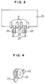
- Fig. 3 is a side elevational view of a main part viewed in the direction indicated by an arrow A of Fig. 1, indicating a positional relation of the aforementioned pick-up rollers 21, feed rollers 22, gate rollers 23, first pinch rollers 25, second pinch rollers 27 and each friction member provided thereon.
- Fig. 4 indicates a relative positional relation particularly of the feed roller 22, the gate roller 23 and the first pinch roller 25, and as illustrated, the gate roller 23 is brought into contact with the feed roller 22 on one side where its outer periphery is constructed partly of the friction member 32, and the first pinch roller 25 is brought into contact with the feed roller 22 on another side where its outer periphery is constructed entirely of the friction member 32, thus constructing first pinching/carrying means.
- the first pinch roller 25 is brought into contact with the feed roller 22 on the side where its outer periphery is constructed entirely of the friction member 32, and is energized by a spring 26 toward the feed roller 22.
- the aforementioned second pinch roller 27 is rotatable round a supporting point 33 serving as a center of rotation, and supported rotatably on a lever 28 energized by a spring 34 clockwise in the illustration, and is pushed toward the feed roller 22. That is, the second pinch roller 27 functions as second pinching/carrying means, and when the lever 28 is turned counterclockwise in the illustration against the spring 34, it comes away from the feed roller 22, but when the force is removed, it is pushed to the feed roller 22.
- reference characters 9A, 9B, 9C denote driving motors for the saves 1A, 1B, 1C respectively
- a reference numeral 29 denotes a bill pinching start point of the carrying pass 3A
- 35 denotes a bill push plate of the safe 1A
- the push plate 35 pushes the bills 20 to the feed rollers 22 through a spring 36.
- a reference numeral 37 denotes a guide member corresponding to a size (short side length) of the bills 20 in the safe 1A, and as will be described hereinlater, an operation of the lever 28 is controlled by the guide member 37.
- a reference numeral 38 indicates the direction in which the saves are moved
- 39 denotes a passage detection sensor for detecting the bills having passed a pinching point of the feed roller 22 and the first pinch roller 25.
- the aforementioned lever 28, spring 34, guide member 37 and other construct an identification part of the length of the bills 20 along the driving direction, and as will be described hereinlater, the second pinch rollers 27 according to the length of the bills 20 are actuated thereby.
- the safe 1A is constructed to be detachable in the direction indicated by the arrow 38, and the gate rollers 23 and the first pinch rollers 25 are mounted on a lower portion of the safe 1A. That is, the construction is such that the gate rollers 23 and the first pinch rollers 25 are pressed to the feed rollers 22 provided on an apparatus body side by setting the safe 1A on the apparatus body of the present embodiment.
- the construction is such that where the bills are not less than 75 mm in the short side length and when the safe 1A is installed, the guide member 37 thrusts the lever 28 on its nose, and detaches the second pinch rollers 27 from the feed rollers 22 to release pinching.
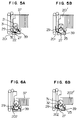
- FIG. 5A and 5B illustrate an operation when the apparatus embodying the invention handles bills 201 longest at 100 mm
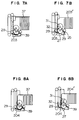
- Figs. 6A and 6B illustrate an operation when the apparatus handles bills 202 shortest at 50 mm
- Figs. 7A and 7B illustrates an operation when bills 203 if 75 mm in length are handled
- Figs. 8A and 8B illustrate an operation when bills 204 of 70 mm in length are handled.
- Figs. 5A to 8B Fig. 5A, Fig. 6A, Fig. 7A and Fig. 8A indicate a condition midway of driving
- Fig. 5B, Fig. 6B, Fig. 7B and Fig. 8B indicate a condition when driving is stopped.
- a position of the aforementioned guide member 37 changes according to the length of bills, and thus a pinching force of the second pinch rollers 27 works as illustrated in Figs. 5A and 5B, Figs. 7A and 7B, but no such force works in Figs. 6A and 6B, Figs. 8A and 8B.
- the feed rollers 22 and the pick-up roller 21 are 40 mm in diameter so as to have the outer periphery longer than a maximum bill length.
- a distance from the first pinch roller 25 to the bill pinching start point 29 of the carrying pass 3A on the rear stage is about 70 mm so as to handle the bills 201, 203 not less than 75 mm in length in the state where a pinching force of the second pinch rollers 27 is not working.
- a distance from the second pinch roller 27 to the pinching start point 29 of the carrying pass 3A on the rear stage is about 45 mm so as to handle the bills 202 which are shortest in length at 50 mm.
- Described next is an operation controlling method when the driving operation comes to stop at a predetermined number of sheets to drive after the operation is started.
- a general operation is such that the feed rollers 22 and the pick-up rollers 21 are driven to rotate by the motor 9A, the bills separated and driven out sheet by sheet are pinched and carried on the feed rollers 22 and the first pinch rollers 25 only or the second pinch rollers 27 together, and are delivered to the carrying pass 3A on the rear stage at the pinching start point 29.
- Figs. 8A and 8B when handling the bills 202, 204 below 75 mm in length, since the pinching force of the second pinch rollers 27 is ready for working, as described hereinbefore, the number of passing bills is counted on the passage detection sensor 39, and after the time required for rear ends of the bills to pass the pinching point of the second pinch rollers 27 passes from the point in time when passage of the rear ends of the predetermined final bills 201, 203 is detected, the motor 9A is shut down. In this case, an operation for driving the ensuing bills 201', 203' will also not be started.
- one sheet of the bill can securely be driven per rotation of the feed rollers and carried to the carrying pass 3A on the rear stage in case every bills are handled.
- the second pinch rollers 27 can be disposed according to the length of bills, therefore a stop operation for the long bills will not be retarded more than necessary, and a capability of the ensuing bills being driven can be minimized.
- the above-described embodiment is only to exemplify the present invention, and hence the invention is not necessary limited, needless to say, to the embodiment.
- the invention may be applied not only to the automatic teller but also extensively to other general paper handling apparatuses.
- the identification part comprising lever, guide member and others will be provided to come on a lower side of papers, and may function to control the second paper carrying means according to the length of papers in the direction where they are driven.
- an advantage inherent therein is such that a paper separating/driving apparatus capable of separating and driving securely even such papers as are variant largely in length, and also disposing a paper pinching point of a carrying pass on the rear stage with a large degree of freedom, and its controlling method can be realized.
- a degree of freedom of the position of the paper pinching point of the carrying pass on the rear stage can be amplified, and thus a degree of freedom at the construction will largely be enhanced when utilizing this to an automatic teller.
Applications Claiming Priority (2)
| Application Number | Priority Date | Filing Date | Title |
|---|---|---|---|
| JP3295576A JP2929806B2 (ja) | 1991-11-12 | 1991-11-12 | 紙葉類分離繰出し装置、および、それを用いた現金自動取引装置 |
| JP295576/91 | 1991-11-12 |
Publications (2)
| Publication Number | Publication Date |
|---|---|
| EP0542226A1 true EP0542226A1 (fr) | 1993-05-19 |
| EP0542226B1 EP0542226B1 (fr) | 1996-02-28 |
Family
ID=17822425
Family Applications (1)
| Application Number | Title | Priority Date | Filing Date |
|---|---|---|---|
| EP19920119287 Expired - Lifetime EP0542226B1 (fr) | 1991-11-12 | 1992-11-11 | Appareil pour séparer et alimenter des papiers et méthode de contrÔle dudit appareil et distributeur automatique de billets fonctionnant selon ladite méthode |
Country Status (3)
| Country | Link |
|---|---|
| EP (1) | EP0542226B1 (fr) |
| JP (1) | JP2929806B2 (fr) |
| DE (1) | DE69208593T2 (fr) |
Cited By (5)
| Publication number | Priority date | Publication date | Assignee | Title |
|---|---|---|---|---|
| WO1995025317A1 (fr) * | 1994-03-16 | 1995-09-21 | Siemens Nixdorf Informationssysteme Ag | Dispositif distributeur de billets |
| EP0821325A1 (fr) * | 1996-06-29 | 1998-01-28 | Scheidt & Bachmann Gmbh | Dispositif de stockage autoremplissable pour des porteurs de données en forme de carte |
| WO1998009899A2 (fr) * | 1996-09-06 | 1998-03-12 | De La Rue International Limited | Distributeur de feuilles et son plateau |
| EP0902399A1 (fr) * | 1997-09-02 | 1999-03-17 | Scheidt & Bachmann Gmbh | Dispositif de stockage pour des porteurs de données en forme de carte |
| FR2799192A1 (fr) * | 1999-10-01 | 2001-04-06 | Poste | Dispositif de distribution automatique de billets de banque ou similaires |
Citations (4)
| Publication number | Priority date | Publication date | Assignee | Title |
|---|---|---|---|---|
| FR2388353A1 (fr) * | 1977-04-19 | 1978-11-17 | Nixdorf Computer Ag | Distributeur de documents tels que des billets de banque |
| US4158456A (en) * | 1976-11-04 | 1979-06-19 | Nixdorf Computer Ag | Device for separating documents, cards and the like, especially paper money bills |
| EP0174200A1 (fr) * | 1984-09-06 | 1986-03-12 | De La Rue Systems Limited | Procédé et appareil pour distribuer des feuilles |
| EP0294055A1 (fr) * | 1987-05-18 | 1988-12-07 | Orient Watch Co., Ltd. | Appareil à amener des feuilles de papier par exemple pour utilisation dans une imprimante |
-
1991
- 1991-11-12 JP JP3295576A patent/JP2929806B2/ja not_active Expired - Lifetime
-
1992
- 1992-11-11 DE DE1992608593 patent/DE69208593T2/de not_active Expired - Fee Related
- 1992-11-11 EP EP19920119287 patent/EP0542226B1/fr not_active Expired - Lifetime
Patent Citations (4)
| Publication number | Priority date | Publication date | Assignee | Title |
|---|---|---|---|---|
| US4158456A (en) * | 1976-11-04 | 1979-06-19 | Nixdorf Computer Ag | Device for separating documents, cards and the like, especially paper money bills |
| FR2388353A1 (fr) * | 1977-04-19 | 1978-11-17 | Nixdorf Computer Ag | Distributeur de documents tels que des billets de banque |
| EP0174200A1 (fr) * | 1984-09-06 | 1986-03-12 | De La Rue Systems Limited | Procédé et appareil pour distribuer des feuilles |
| EP0294055A1 (fr) * | 1987-05-18 | 1988-12-07 | Orient Watch Co., Ltd. | Appareil à amener des feuilles de papier par exemple pour utilisation dans une imprimante |
Non-Patent Citations (2)
| Title |
|---|
| PATENT ABSTRACTS OF JAPAN vol. 13, no. 485 (M-887)6 November 1989 & JP-A-11 92 630 ( HITACHI LTD ) 2 August 1989 * |
| PATENT ABSTRACTS OF JAPAN vol. 7, no. 85 (M-206)(1230) 9 April 1983 & JP-A-58 011 439 ( HITACHI SESAKUSHO K.K. ) 22 January 1983 * |
Cited By (12)
| Publication number | Priority date | Publication date | Assignee | Title |
|---|---|---|---|---|
| WO1995025317A1 (fr) * | 1994-03-16 | 1995-09-21 | Siemens Nixdorf Informationssysteme Ag | Dispositif distributeur de billets |
| US5697517A (en) * | 1994-03-16 | 1997-12-16 | Siemens Nixdorf Informationssysteme Aktiengesellschaft | Dispensing unit for banknotes |
| EP0821325A1 (fr) * | 1996-06-29 | 1998-01-28 | Scheidt & Bachmann Gmbh | Dispositif de stockage autoremplissable pour des porteurs de données en forme de carte |
| US6039314A (en) * | 1996-06-29 | 2000-03-21 | Scheidt & Bachmann Gmbh | Self-filling storage device for card-shaped data carriers |
| WO1998009899A2 (fr) * | 1996-09-06 | 1998-03-12 | De La Rue International Limited | Distributeur de feuilles et son plateau |
| WO1998009899A3 (fr) * | 1996-09-06 | 1998-07-23 | De La Rue Syst | Distributeur de feuilles et son plateau |
| US6189881B1 (en) | 1996-09-06 | 2001-02-20 | De La Rue International Limited | Sheet dispensing apparatus and tray |
| CN1075464C (zh) * | 1996-09-06 | 2001-11-28 | 德拉鲁国际公司 | 票单分配设备 |
| EP0902399A1 (fr) * | 1997-09-02 | 1999-03-17 | Scheidt & Bachmann Gmbh | Dispositif de stockage pour des porteurs de données en forme de carte |
| US5904466A (en) * | 1997-09-02 | 1999-05-18 | Scheidt & Bachmann Gmbh | Storage device for card-shaped data carriers |
| FR2799192A1 (fr) * | 1999-10-01 | 2001-04-06 | Poste | Dispositif de distribution automatique de billets de banque ou similaires |
| WO2001025126A1 (fr) * | 1999-10-01 | 2001-04-12 | La Poste | Dispositif de distribution automatique de billets de banque ou similaires |
Also Published As
| Publication number | Publication date |
|---|---|
| DE69208593T2 (de) | 1996-07-11 |
| JP2929806B2 (ja) | 1999-08-03 |
| EP0542226B1 (fr) | 1996-02-28 |
| DE69208593D1 (de) | 1996-04-04 |
| JPH05132183A (ja) | 1993-05-28 |
Similar Documents
| Publication | Publication Date | Title |
|---|---|---|
| EP0393589B1 (fr) | Appareil de délivrance de papier en continu | |
| JP5274999B2 (ja) | 紙幣取扱装置 | |
| EP0793199B1 (fr) | Machine de traitement de billets de banque | |
| EP1302425B1 (fr) | Dispositif d'empilage de billets de banque | |
| EP0793197B1 (fr) | Machine de traitement de billets de banque | |
| AU706031B2 (en) | Sheet feeding apparatus and method | |
| EP0814439A3 (fr) | Méthode et dispositif de tri, d'authentification et de comptage de documents | |
| EP0174009A2 (fr) | Distributeur d'argent liquide | |
| EP0793201B1 (fr) | Machine de traitement de billets de banque | |
| US4732375A (en) | Apparatus for handling strip-like media | |
| EP0174200A1 (fr) | Procédé et appareil pour distribuer des feuilles | |
| JPH0769485A (ja) | シート処理装置 | |
| EP0132329B1 (fr) | Dispositif d'alimentation en feuille | |
| JPH08507743A (ja) | 積重ねシート装置 | |
| EP0744718B1 (fr) | Dispositif pour transporter des feuilles | |
| US4552350A (en) | Transport for diverted and purged sheets in a sheet dispenser | |
| WO2005088564A1 (fr) | Support de feuilles | |
| EP0542226A1 (fr) | Appareil pour séparer et alimenter des papiers et méthode de contrôle dudit appareil et distributeur automatique de billets fonctionnant selon ladite méthode | |
| EP0793200A2 (fr) | Machine de traitement de billets de banque | |
| US4877232A (en) | Paper discharge apparatus | |
| GB2113187A (en) | Apparatus for detecting the passage of multiple superposed documents along a feed path | |
| JPH10329962A (ja) | シート送り装置 | |
| EP0177551B1 (fr) | Distributeur de feuilles | |
| JP4038357B2 (ja) | 紙葉類集積装置および紙葉類取扱装置 | |
| JP3927290B2 (ja) | 紙葉類収納装置 |
Legal Events
| Date | Code | Title | Description |
|---|---|---|---|
| PUAI | Public reference made under article 153(3) epc to a published international application that has entered the european phase |
Free format text: ORIGINAL CODE: 0009012 |
|
| 17P | Request for examination filed |
Effective date: 19930316 |
|
| AK | Designated contracting states |
Kind code of ref document: A1 Designated state(s): DE FR GB |
|
| 17Q | First examination report despatched |
Effective date: 19930621 |
|
| GRAA | (expected) grant |
Free format text: ORIGINAL CODE: 0009210 |
|
| AK | Designated contracting states |
Kind code of ref document: B1 Designated state(s): DE FR GB |
|
| REF | Corresponds to: |
Ref document number: 69208593 Country of ref document: DE Date of ref document: 19960404 |
|
| ET | Fr: translation filed | ||
| PLBE | No opposition filed within time limit |
Free format text: ORIGINAL CODE: 0009261 |
|
| STAA | Information on the status of an ep patent application or granted ep patent |
Free format text: STATUS: NO OPPOSITION FILED WITHIN TIME LIMIT |
|
| 26N | No opposition filed | ||
| REG | Reference to a national code |
Ref country code: GB Ref legal event code: IF02 |
|
| PGFP | Annual fee paid to national office [announced via postgrant information from national office to epo] |
Ref country code: FR Payment date: 20021023 Year of fee payment: 11 |
|
| PGFP | Annual fee paid to national office [announced via postgrant information from national office to epo] |
Ref country code: GB Payment date: 20021029 Year of fee payment: 11 |
|
| PGFP | Annual fee paid to national office [announced via postgrant information from national office to epo] |
Ref country code: DE Payment date: 20021205 Year of fee payment: 11 |
|
| PG25 | Lapsed in a contracting state [announced via postgrant information from national office to epo] |
Ref country code: GB Free format text: LAPSE BECAUSE OF NON-PAYMENT OF DUE FEES Effective date: 20031111 |
|
| PG25 | Lapsed in a contracting state [announced via postgrant information from national office to epo] |
Ref country code: DE Free format text: LAPSE BECAUSE OF NON-PAYMENT OF DUE FEES Effective date: 20040602 |
|
| GBPC | Gb: european patent ceased through non-payment of renewal fee |
Effective date: 20031111 |
|
| PG25 | Lapsed in a contracting state [announced via postgrant information from national office to epo] |
Ref country code: FR Free format text: LAPSE BECAUSE OF NON-PAYMENT OF DUE FEES Effective date: 20040730 |
|
| REG | Reference to a national code |
Ref country code: FR Ref legal event code: ST |