EP0902399A1 - Dispositif de stockage pour des porteurs de données en forme de carte - Google Patents
Dispositif de stockage pour des porteurs de données en forme de carte Download PDFInfo
- Publication number
- EP0902399A1 EP0902399A1 EP97115156A EP97115156A EP0902399A1 EP 0902399 A1 EP0902399 A1 EP 0902399A1 EP 97115156 A EP97115156 A EP 97115156A EP 97115156 A EP97115156 A EP 97115156A EP 0902399 A1 EP0902399 A1 EP 0902399A1
- Authority
- EP
- European Patent Office
- Prior art keywords
- magazine
- roller
- storage device
- carrier
- card
- Prior art date
- Legal status (The legal status is an assumption and is not a legal conclusion. Google has not performed a legal analysis and makes no representation as to the accuracy of the status listed.)
- Granted
Links
Images


Classifications
-
- G—PHYSICS
- G07—CHECKING-DEVICES
- G07B—TICKET-ISSUING APPARATUS; FARE-REGISTERING APPARATUS; FRANKING APPARATUS
- G07B3/00—Machines for issuing preprinted tickets
- G07B3/04—Machines for issuing preprinted tickets from a stack
-
- Y—GENERAL TAGGING OF NEW TECHNOLOGICAL DEVELOPMENTS; GENERAL TAGGING OF CROSS-SECTIONAL TECHNOLOGIES SPANNING OVER SEVERAL SECTIONS OF THE IPC; TECHNICAL SUBJECTS COVERED BY FORMER USPC CROSS-REFERENCE ART COLLECTIONS [XRACs] AND DIGESTS
- Y10—TECHNICAL SUBJECTS COVERED BY FORMER USPC
- Y10S—TECHNICAL SUBJECTS COVERED BY FORMER USPC CROSS-REFERENCE ART COLLECTIONS [XRACs] AND DIGESTS
- Y10S414/00—Material or article handling
- Y10S414/10—Associated with forming or dispersing groups of intersupporting articles, e.g. stacking patterns
- Y10S414/102—Associated with forming or dispersing groups of intersupporting articles, e.g. stacking patterns including support for group
- Y10S414/103—Vertically shiftable
Definitions
- the invention relates to a storage device for card-shaped data carriers with at least one memory in which the card-shaped data carrier on a vertically movable support base are arranged one on top of the other and from which the top data carrier by a separating roller laterally removable through an output slot and a drive roller for transfer can be fed to downstream processing and / or output.
- Such storage devices for card-shaped data carriers are in different Embodiments, for example for issuing user authorization cards known for parking garages.
- European Patent application 96 110 551.7 is a self-filling storage device described for card-shaped data carriers that consist of several memories exists and an automatic filling and / or emptying of all storage enables.
- the invention has for its object to provide a memory device of the known type with at least one memory that is structurally simple and therefore inexpensive to manufacture and has a basic structure that can be expanded in various stages and has a high level of functional reliability, so that the memory device can be adapted to different requirements.
- the solution to this problem by the invention is characterized in that the support base is arranged on a carriage which is guided in a height-adjustable manner on a magazine carrier and can be driven by a motor by an endless flexible tension element which is arranged on the magazine carrier via two deflection rollers arranged outside the movement range of the carriage is guided and drives two drive rollers of the same diameter, freely rotatably mounted on the slide, which are connected to one another by a differential gear.
- the endless flexible traction element guided over the deflection rollers for example A timing belt, or chain, is driven by the engine in one of two possible directions of rotation driven and in turn drives with each Run on one of the two drive rollers, which are freely rotatable on the slide are. Since these drive rollers have the same diameter and the same If the direction of rotation were driven, there would be no movement of the slide. This is only achieved in that the two drive rollers by a Differential gears are interconnected. This differential gear causes the twist angle of the two drive rollers despite their being the same Diameter is different. Because the two strands of the flexible tension element is forced to move at the same speed this results in a relative movement of the slide to the flexible tension element and thus forced to the magazine carrier. The direction and size of this Relative movement is based on the direction of rotation of the motor and the difference in Angle of rotation of the drive rollers dependent, so that they by training of the respective differential gear can be determined.
- the differential gear through two through an endless flexible connecting element connected differential roles formed, each with a drive role non-rotatably arranged on a connecting shaft and with different Diameter are formed. Due to the different diameters the differential rollers and their connection by means of an endless flexible Traction element, in particular a toothed belt or a chain, is a different angle of rotation is imposed on the drive rollers causes the carriage supporting the drive rollers to perform a compensatory movement in the longitudinal direction of the circumferential flexible tension element, i.e. in Longitudinal direction of the magazine carrier on which the guide rollers for the flexible tension element are stored.
- This compensatory movement depends on Difference in the diameter of the differential rollers and results in a self-locking Drive for the supporting floor, which is the linear processing large Forces and a very precise movement of the tray over its entire length Movement range allows, as is the case for the controlled feeding of the individual card-shaped data carriers to the magazine output slot are required is.
- these are flexible Tension element and the flexible connecting element as a toothed belt and the Drive rollers and differential rollers are designed as toothed belt rollers. As a result, there is a slip between with little technical effort this drive parts excluded.
- the invention proposes the carriage by means of rollers to run in the longitudinal direction of the magazine carrier, so that a cover-free Movement of the carriage is achieved.
- the memory consists of the Magazine carrier and an interchangeable magazine that holds the card-shaped data carriers with a fixed magazine bottom and can be fixed to the magazine carrier by means of two support arms. This results in a structurally simple structure and a simple replacement of each Memory.
- the invention also proposes using the magazine base to provide at least one passage opening for the supporting floor.
- This Training enables a filled magazine in which the card-shaped Data carriers lie on the magazine base, to be attached to the magazine carrier, the supporting floor is in its lowest position, the one below of the magazine base attached to the magazine carrier.
- Raising the support floor passes through the passage opening in the magazine bottom and takes over the card-shaped data carriers that thus lifted off the magazine bottom and one after the other as required Output slot to be guided.
- the magazine is to prevent during the operation of the storage device according to a further feature of the invention with in side recesses protruding wall parts. These wall parts prevent the magazine from being removed from the magazine carrier if the Tragêt in the area of the magazine, i.e. located in his work area.
- the magazine is with formed a C-shaped cross section, its opposing Pour into one of two opposite recesses protrude from the supporting floor. This results in a particularly simple design of the magazine, which is only in the lowest end position of the tray is removable from the magazine carrier.
- the magazine is on it Bottom beveled and correspondingly sloping downwards Support arms attached, which are attached to the magazine carrier.
- the magazine by means of a Magazine carrier arranged tab set with a in a bolt opening engaging locking bolt is provided.
- the Motor housing around a parallel, but eccentric to the motor axis Swivel axis is pivotally mounted on the magazine carrier.
- the motor housing of the selection motor is according to the invention via its as Separating roller serving output roller and above the top one card-shaped data carrier can be pivoted into its operative position through the supporting base, so that always a card-shaped data carrier from the side Output slot of the magazine can be output if the respective top card-shaped data carrier in its output position in front of the Output slot is transferred through the tray.
- the operative position of the singling role is monitored by a switch which by the pivoting movement the motor housing is actuated, is a targeted output of the top card-shaped data carrier possible as soon as this brought into its dispensing position by movement of the tray has been.
- the transport roller according to a further feature of the invention laterally above the output slot of the magazine and arranged by a Transport motor can be driven, the one via an intermediate gear Retaining roller arranged below the transport roller in the same direction of rotation how the feed roller drives, being between this retention roller and the transport roller is formed a gap which is larger than the thickness and is less than twice the thickness of the card-shaped data carrier.
- This inventive design of the separation device downstream Transport device ensures on the one hand that only the top card-shaped data carrier is pulled out of the magazine as a especially entrained by friction between the data carriers additional data carriers through the in the opposite transport direction Transport roller driven retention roller is returned to the magazine.
- this basic design of the transport device enables that according to a further feature of the invention that of transport and retention role a puller roller pair is subordinated to an existing roller pair, the one from the idler gear in the same direction as the transport roller driven roller and a freely rotatable, against the driven There is a counter roller pressed by spring force.
- the the Card-shaped to be fed or issued for further processing Data carrier is thus captured by two pairs of roles, which is a very high functional reliability results.
- the transport roller in both directions of rotation can be driven and with one arranged above Pressure roller cooperates, the gap formed by these rollers card-shaped data carrier from a neighboring memory for distribution are supplied, the gap formed by these rollers Guide plate for card-shaped coming from a neighboring store Disk is assigned.
- each adjacent memory to each other in height by the distance between that through the Transport roller and the retention roller and the gap formed by the Transport roller and the pressure roller formed gap.
- each adjacent memory to each other in height by the distance between that through the Transport roller and the retention roller and the gap formed by the Transport roller and the pressure roller formed gap.
- a guide plate is arranged above the guide plate, the card-shaped one Data carrier of the neighboring storage through the transport roller and Pressure roller feeds formed gap.
- the invention proposes the selection engine, the To arrange the transport motor and all associated rollers on a support housing, that above the interchangeable magazine and in front of the associated one Magazine carrier is arranged on the magazine carrier. This gives a particularly simple construction for the memory device according to the invention.
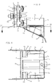
- the storage device shown in Figures 1 to 3 only includes a memory, which in turn consists of an interchangeable magazine 1 and a magazine carrier 2 and the associated facilities for storage and the transport of the card-shaped data carriers stored in the magazine 1 D and for the separation and removal of the individual Disk D exists.
- magazine 1 there are data carriers of the same thickness stored, for example EC cards, chip cards, transponder cards and Magnetic cards.
- card-shaped data carriers D of different types and Thickness must be saved for each card type and card thickness Magazine 1 are arranged.
- the structure and mode of operation of these existing storage from magazine 1 and magazine carrier 2 is identical, so that based on that shown in Figures 1 to 3 Embodiment only such a memory is described.
- the magazine 1 shows a C-shaped cross section, as can be seen from FIGS. 8 and 9.
- the front 1a forming the web of this C-shaped cross section itself forming a right angle from the parallel to each other extending legs of the C-shaped cross section formed side walls 1b of magazine 1, which at the end turned at a right angle are and form opposing legs 1c.
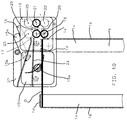
- the side walls 1b according to FIG. 10 form cover strips 1d bent over.
- the magazine 1 is provided with an output slot 1e.
- the lower end of the magazine 1 is chamfered.
- the magazine 1 which at Exemplary embodiment by two strip-shaped supports on the side walls 1b is formed, which has a through opening between them Form tray 3.
- the card-shaped data carrier D On this firmly arranged in the magazine 1 Magazine bottom 1f, the card-shaped data carrier D, if one filled magazine 1 is attached to the magazine carrier 2.
- the magazine carrier 2 which is in the embodiment is formed with a U-shaped cross section, in its lower Provide area with two inclined support arms 2a, one have an angular cross-section, the vertical leg of the lateral Management of the magazine 1 and its horizontal leg to support the Magazine 1 serves.
- a filled magazine 1 is from bottom to top of the Magazine carrier 2 attached, guided between the support arms 2a and then locked by a tab 2b arranged on the magazine carrier 2, with a locking bolt engaging in a locking opening of the magazine 1 2c is provided.
- a vertically movable support base 3 is on the magazine support 2 movably guided, an embodiment of which is best shown in the figures 8 and 9 can be seen.
- This support floor 3 is on a slide 4 arranged, which consists of two mutually parallel slide walls 4a and 4b. While the front carriage wall 4a integrally with the Support base 3 is formed by an angle plate, it is in the rear slide wall 4b around a separate sheet metal part, which according to FIG by means of two bolts 4c with the front slide wall 4a connected is.
- the support base 3 shown in a top view in FIG. 9 is forked with two spaced-apart floor halves 3a are formed. Each Bottom half 3a is provided with a lateral recess 3b, in each a tavern 1c of the magazine 1 protrudes, as can be seen in FIG. This ensures that the magazine 1 is not from Magazine carrier 2 can be removed as long as the base 3 in his work area.
- the carriage 4 is driven by a at the lower end of the Magazine carrier 2 arranged motor 6 via a flexible tension element, the is designed as a toothed belt 7 in the embodiment, but also as V-belt or chain can be executed.
- This toothed belt 7 is over two arranged outside the range of motion 4 of the magazine carrier 2 Deflection rollers 8a and 8b, of which the lower deflection roller 8a on the Drive shaft of the motor 6 sits and thus from this motor 6, namely in is drivable in both directions.
- each drive roller 9 is two laterally offset guide rollers 10 assigned, which are freely rotatable on a Axis 11 are mounted on which the rollers 5 are freely rotatable ( Figure 6).
- the drive rollers 9 are non-rotatable Arranged on a shaft 12, which to the rear from the rear sled wall 4b of the carriage 4 protrudes, each on this protruding end
- Each shaft 12 has a differential roller 13a or 13b rotatably attached.
- the differential rollers 13a and 13b have a different one Diameter or a different number of teeth.
- the drive rollers 9 with 21 teeth
- the differential roller 13a also with Provide 21 teeth
- the differential roller 13b with 18 teeth.
- the Differential rollers 13a and 13b are endlessly flexible with each other Connection element connected, which in turn in the embodiment as endless toothed belt 14 is executed (Fig. 7). The better clarity because of Figures 4 to 6 and 8, both the toothed belt 7 and the toothed belt 14 has been omitted. 2, the toothed belt 7 only indicated by dash-dotted lines; the timing belt 14 was again omitted.
- the drive rollers 9 of the Slide 4 with the same direction of rotation and with the same angular velocity driven.
- these drive rollers 9 are non-rotatable via the shafts 12 are connected to the differential rollers 13a and 13b, respectively have different number of teeth, depending on the direction of rotation of the Timing belt 7 a relative movement of the carriage 4 in the longitudinal direction of the Magazine carrier 2, since that of the differential rollers 13a and 13b different rotation angles imposed by a relative movement of the slide 4 compared to the rotating toothed belt 7 Need to become.
- the differential gear formed in this way is for the circumferential toothed belt 7 self-locking and enables the rulers Processing large forces.
- the ratio of the number of teeth of the differential rollers 13a and 13b gives the path for the movement of the carriage 4 relative to the Magazine carrier 2 and thus for the movement of the carriage 4 arranged tray 3.
- a selection motor 15 is provided, the drive roller as Separating roller 15a is formed on the top of each top card-shaped data carrier D acts in magazine 1.
- the Motor housing of the selection motor 15 is parallel, however Eccentric pivot axis 15b pivotable mounted on the magazine carrier 2 and provided with a switching arm 15c, which with a switch 16 cooperates.
- the pair of rollers consisting of transport roller 17 and retaining roller 18 in the embodiment, a puller roller pair arranged, which consists of a driven by the intermediate gear 20 in the same direction with the transport roller 17 Roller 21 and a freely rotatable, against the driven roller 21st there is a counter roller 22 pressed by spring force.
- the transport roller 17 can of the transport motor 19 in both directions of rotation are driven not only from the output slot 1e of the associated magazine 1 coming data carrier D for further processing or the output, but also from an upstream To transport magazine coming data carriers.
- the gap formed by these rollers 17 and 23 is one Assigned guide plate 24 on which the magazine 1 above the Separating roller 15a lying on data carrier D.
- the roller 21 driven in the same direction with the transport roller 17 is at Embodiment assigned a pressure roller 25. To use this enable, has the retaining roller 18 when driving the transport roller in Clockwise a freewheel.
- the storage device comprises a plurality of memories, as shown in FIG. 11 is shown based on two memories, are adjacent memories to each other in height by the distance between that through the Transport roller 17 and the retaining roller 18 and the gap formed by the transport roller 18 and the pressure roller 23 formed gap. On in this way it is ensured according to FIG. 11 that from the magazine 1 of the left-hand memory deducted card-shaped data carrier D, the leave the transport device formed by the transport motor 19, reliably on the top of the guide plate 24 of the right memory arrive and here between the transport roller 17 and the pressure roller 23 formed gap are fed.
- Figures 10 and 11 finally show that in front of the magazine carrier 2 Support housing 27 is arranged on which the selection motor 15, the Transport motor 19 and all associated roles are arranged. It This also results in a structurally simple design for this assembly Unit.
Landscapes
- Physics & Mathematics (AREA)
- General Physics & Mathematics (AREA)
- Conveying Record Carriers (AREA)
- Credit Cards Or The Like (AREA)
- Sheets, Magazines, And Separation Thereof (AREA)
Priority Applications (4)
| Application Number | Priority Date | Filing Date | Title |
|---|---|---|---|
| AT97115156T ATE252258T1 (de) | 1997-09-02 | 1997-09-02 | Speichervorrichtung für kartenförmige datenträger |
| DE59710867T DE59710867D1 (de) | 1997-09-02 | 1997-09-02 | Speichervorrichtung für kartenförmige Datenträger |
| EP97115156A EP0902399B1 (fr) | 1997-09-02 | 1997-09-02 | Dispositif de stockage pour des porteurs de données en forme de carte |
| US09/146,916 US5904466A (en) | 1997-09-02 | 1998-09-02 | Storage device for card-shaped data carriers |
Applications Claiming Priority (1)
| Application Number | Priority Date | Filing Date | Title |
|---|---|---|---|
| EP97115156A EP0902399B1 (fr) | 1997-09-02 | 1997-09-02 | Dispositif de stockage pour des porteurs de données en forme de carte |
Publications (2)
| Publication Number | Publication Date |
|---|---|
| EP0902399A1 true EP0902399A1 (fr) | 1999-03-17 |
| EP0902399B1 EP0902399B1 (fr) | 2003-10-15 |
Family
ID=8227305
Family Applications (1)
| Application Number | Title | Priority Date | Filing Date |
|---|---|---|---|
| EP97115156A Expired - Lifetime EP0902399B1 (fr) | 1997-09-02 | 1997-09-02 | Dispositif de stockage pour des porteurs de données en forme de carte |
Country Status (4)
| Country | Link |
|---|---|
| US (1) | US5904466A (fr) |
| EP (1) | EP0902399B1 (fr) |
| AT (1) | ATE252258T1 (fr) |
| DE (1) | DE59710867D1 (fr) |
Cited By (1)
| Publication number | Priority date | Publication date | Assignee | Title |
|---|---|---|---|---|
| CN101315705B (zh) * | 2007-05-29 | 2012-05-02 | 上海华铭智能终端设备股份有限公司 | 一种自动售票装置 |
Families Citing this family (10)
| Publication number | Priority date | Publication date | Assignee | Title |
|---|---|---|---|---|
| US6199857B1 (en) | 1999-09-22 | 2001-03-13 | Fargo Electronics, Inc. | I. D. card output stacker |
| US6776263B2 (en) * | 2000-05-19 | 2004-08-17 | Esw-Extel Systems Wedel Gesellschaft Fuer Austruestung Mbh | Elevator system for the vertical transport of loads in an aircraft |
| EP1270488B1 (fr) * | 2001-06-28 | 2008-04-02 | Inventio Ag | Entrainement pour ascenseur |
| US7975807B2 (en) * | 2004-01-20 | 2011-07-12 | Franklin Samuel H | Elevator climbing system |
| FR2872611B1 (fr) * | 2004-07-02 | 2006-09-29 | Thales Sa | Container empileur de cartes sans contact et module recycleur de cartes comportant un tel container |
| US8220354B2 (en) * | 2006-06-28 | 2012-07-17 | Genmark Automation, Inc. | Belt-driven robot having extended Z-axis motion |
| US8701519B2 (en) * | 2006-06-28 | 2014-04-22 | Genmark Automation, Inc. | Robot with belt-drive system |
| FI120091B (fi) * | 2006-11-10 | 2009-06-30 | Kone Corp | Vastapainoton vetopyörähissi |
| EP2119659B1 (fr) * | 2008-05-16 | 2014-07-02 | ThyssenKrupp Elevator AG | Element allongé pour une gaine d'ascenseur |
| CN101635064B (zh) * | 2008-12-03 | 2012-08-15 | 高新现代智能系统股份有限公司 | 一种卡片自动发放装置 |
Citations (4)
| Publication number | Priority date | Publication date | Assignee | Title |
|---|---|---|---|---|
| US3416705A (en) * | 1965-03-02 | 1968-12-17 | Taller & Cooper Inc | Ticket dispenser with automatic feed and signal |
| EP0241342A1 (fr) * | 1986-03-25 | 1987-10-14 | Electronique Serge Dassault | Distributeur-programmateur automatique de cartes à micro-circuit |
| EP0542226A1 (fr) * | 1991-11-12 | 1993-05-19 | Hitachi, Ltd. | Appareil pour séparer et alimenter des papiers et méthode de contrôle dudit appareil et distributeur automatique de billets fonctionnant selon ladite méthode |
| DE19605106A1 (de) * | 1995-02-10 | 1996-08-14 | Nec Corp | Vorrichtung zum Zuführen von Bogen unter Ausnutzung von Reibung |
Family Cites Families (3)
| Publication number | Priority date | Publication date | Assignee | Title |
|---|---|---|---|---|
| US651236A (en) * | 1900-01-02 | 1900-06-05 | Daniel Corcoran | Elevator. |
| US4921388A (en) * | 1986-07-07 | 1990-05-01 | Systems Mailing Research, Inc. | Envelope opener and load separator |
| US5240370A (en) * | 1990-06-01 | 1993-08-31 | Komori Corporation | Pile board inserting method and a pile board inserting machine for carrying out the same |
-
1997
- 1997-09-02 EP EP97115156A patent/EP0902399B1/fr not_active Expired - Lifetime
- 1997-09-02 AT AT97115156T patent/ATE252258T1/de active
- 1997-09-02 DE DE59710867T patent/DE59710867D1/de not_active Expired - Lifetime
-
1998
- 1998-09-02 US US09/146,916 patent/US5904466A/en not_active Expired - Lifetime
Patent Citations (4)
| Publication number | Priority date | Publication date | Assignee | Title |
|---|---|---|---|---|
| US3416705A (en) * | 1965-03-02 | 1968-12-17 | Taller & Cooper Inc | Ticket dispenser with automatic feed and signal |
| EP0241342A1 (fr) * | 1986-03-25 | 1987-10-14 | Electronique Serge Dassault | Distributeur-programmateur automatique de cartes à micro-circuit |
| EP0542226A1 (fr) * | 1991-11-12 | 1993-05-19 | Hitachi, Ltd. | Appareil pour séparer et alimenter des papiers et méthode de contrôle dudit appareil et distributeur automatique de billets fonctionnant selon ladite méthode |
| DE19605106A1 (de) * | 1995-02-10 | 1996-08-14 | Nec Corp | Vorrichtung zum Zuführen von Bogen unter Ausnutzung von Reibung |
Cited By (1)
| Publication number | Priority date | Publication date | Assignee | Title |
|---|---|---|---|---|
| CN101315705B (zh) * | 2007-05-29 | 2012-05-02 | 上海华铭智能终端设备股份有限公司 | 一种自动售票装置 |
Also Published As
| Publication number | Publication date |
|---|---|
| DE59710867D1 (de) | 2003-11-20 |
| EP0902399B1 (fr) | 2003-10-15 |
| ATE252258T1 (de) | 2003-11-15 |
| US5904466A (en) | 1999-05-18 |
Similar Documents
| Publication | Publication Date | Title |
|---|---|---|
| DE2555425C2 (de) | Vorrichtung zum Einschlagen von Papierriesen | |
| DE2717345C2 (de) | Wertscheingeber | |
| DE3445249A1 (de) | Vorrichtung zum transportieren von gegenstaenden | |
| AT13789U1 (de) | Kommissioniereinrichtung | |
| DE3304098C2 (de) | Pflanzmaschine | |
| EP0564901B1 (fr) | Dispositif d'avance pour tÔle | |
| EP0902399B1 (fr) | Dispositif de stockage pour des porteurs de données en forme de carte | |
| DE19510649C2 (de) | Transportvorrichtung | |
| DE1957002B2 (de) | Fördereinrichtung zum Fördern von Zigaretten | |
| DE2618439C2 (de) | Transporteinrichtung für die Auswertung von Identifizierungskarten | |
| EP0017014B1 (fr) | Imprimante à aiguilles avec dispositif de coupe | |
| CH676253A5 (fr) | ||
| DE2127310C3 (de) | Fördereinrichtung für Flaschen oder ähnliches Fördergut | |
| DE3315495A1 (de) | Vorrichtung zum lagern von papierbogen o.dgl. | |
| DE69325069T2 (de) | System mit einer separaten Beschickungseinheit für streifenförmiges Verpackungsmaterial | |
| CH673035A5 (fr) | ||
| DE69500823T2 (de) | Tragleiterführungsmechanismus für Jalousiezusammensetzungsapparat | |
| EP0466006A2 (fr) | Support de râcle pour un dispositif d'enduction | |
| EP0423519B1 (fr) | Transporteur pour le transfert de pots de filature et utilisation du transporteur | |
| EP1351872B1 (fr) | Dispositif pour distribuer ou recevoir des feuillets individuels | |
| DE3722284A1 (de) | Vorschubeinrichtung, insbesondere fuer dosenzargen | |
| DE10105242C1 (de) | Vorrichtung zum stapelförmigen Ablegen von Blättern | |
| DE3713431A1 (de) | Schienengebundene foerderanlage | |
| DE69402500T2 (de) | Automatische Abgabevorrichtung für Gegenstände | |
| WO1991000232A1 (fr) | Chariot d'entreposage et de transfert de porteurs de marchandises |
Legal Events
| Date | Code | Title | Description |
|---|---|---|---|
| PUAI | Public reference made under article 153(3) epc to a published international application that has entered the european phase |
Free format text: ORIGINAL CODE: 0009012 |
|
| 17P | Request for examination filed |
Effective date: 19980505 |
|
| AK | Designated contracting states |
Kind code of ref document: A1 Designated state(s): AT CH DE FR LI NL |
|
| AKX | Designation fees paid |
Free format text: AT CH DE FR LI NL |
|
| GRAH | Despatch of communication of intention to grant a patent |
Free format text: ORIGINAL CODE: EPIDOS IGRA |
|
| GRAS | Grant fee paid |
Free format text: ORIGINAL CODE: EPIDOSNIGR3 |
|
| GRAA | (expected) grant |
Free format text: ORIGINAL CODE: 0009210 |
|
| AK | Designated contracting states |
Kind code of ref document: B1 Designated state(s): AT CH DE FR LI NL |
|
| REG | Reference to a national code |
Ref country code: CH Ref legal event code: NV Representative=s name: DR. LUSUARDI AG Ref country code: CH Ref legal event code: EP |
|
| REF | Corresponds to: |
Ref document number: 59710867 Country of ref document: DE Date of ref document: 20031120 Kind code of ref document: P |
|
| ET | Fr: translation filed | ||
| PLBE | No opposition filed within time limit |
Free format text: ORIGINAL CODE: 0009261 |
|
| STAA | Information on the status of an ep patent application or granted ep patent |
Free format text: STATUS: NO OPPOSITION FILED WITHIN TIME LIMIT |
|
| 26N | No opposition filed |
Effective date: 20040716 |
|
| REG | Reference to a national code |
Ref country code: CH Ref legal event code: PFA Owner name: SCHEIDT & BACHMANN GMBH Free format text: SCHEIDT & BACHMANN GMBH#BREITE STRASSE 132#D-41238 MOENCHENGLADBACH (DE) -TRANSFER TO- SCHEIDT & BACHMANN GMBH#BREITE STRASSE 132#D-41238 MOENCHENGLADBACH (DE) |
|
| PGFP | Annual fee paid to national office [announced via postgrant information from national office to epo] |
Ref country code: CH Payment date: 20110923 Year of fee payment: 15 |
|
| PGFP | Annual fee paid to national office [announced via postgrant information from national office to epo] |
Ref country code: AT Payment date: 20110914 Year of fee payment: 15 Ref country code: FR Payment date: 20110928 Year of fee payment: 15 |
|
| PGFP | Annual fee paid to national office [announced via postgrant information from national office to epo] |
Ref country code: NL Payment date: 20110929 Year of fee payment: 15 |
|
| REG | Reference to a national code |
Ref country code: NL Ref legal event code: V1 Effective date: 20130401 |
|
| REG | Reference to a national code |
Ref country code: CH Ref legal event code: PL |
|
| REG | Reference to a national code |
Ref country code: AT Ref legal event code: MM01 Ref document number: 252258 Country of ref document: AT Kind code of ref document: T Effective date: 20120902 |
|
| REG | Reference to a national code |
Ref country code: FR Ref legal event code: ST Effective date: 20130531 |
|
| PG25 | Lapsed in a contracting state [announced via postgrant information from national office to epo] |
Ref country code: LI Free format text: LAPSE BECAUSE OF NON-PAYMENT OF DUE FEES Effective date: 20120930 Ref country code: AT Free format text: LAPSE BECAUSE OF NON-PAYMENT OF DUE FEES Effective date: 20120902 Ref country code: CH Free format text: LAPSE BECAUSE OF NON-PAYMENT OF DUE FEES Effective date: 20120930 |
|
| PG25 | Lapsed in a contracting state [announced via postgrant information from national office to epo] |
Ref country code: FR Free format text: LAPSE BECAUSE OF NON-PAYMENT OF DUE FEES Effective date: 20121001 Ref country code: NL Free format text: LAPSE BECAUSE OF NON-PAYMENT OF DUE FEES Effective date: 20130401 |
|
| PGFP | Annual fee paid to national office [announced via postgrant information from national office to epo] |
Ref country code: DE Payment date: 20141007 Year of fee payment: 18 |
|
| REG | Reference to a national code |
Ref country code: DE Ref legal event code: R119 Ref document number: 59710867 Country of ref document: DE |
|
| PG25 | Lapsed in a contracting state [announced via postgrant information from national office to epo] |
Ref country code: DE Free format text: LAPSE BECAUSE OF NON-PAYMENT OF DUE FEES Effective date: 20160401 |