EP0541972A1 - Behälter für fliessfähige Substanzen - Google Patents
Behälter für fliessfähige Substanzen Download PDFInfo
- Publication number
- EP0541972A1 EP0541972A1 EP92117405A EP92117405A EP0541972A1 EP 0541972 A1 EP0541972 A1 EP 0541972A1 EP 92117405 A EP92117405 A EP 92117405A EP 92117405 A EP92117405 A EP 92117405A EP 0541972 A1 EP0541972 A1 EP 0541972A1
- Authority
- EP
- European Patent Office
- Prior art keywords
- film tube
- ring
- container according
- cap
- film
- Prior art date
- Legal status (The legal status is an assumption and is not a legal conclusion. Google has not performed a legal analysis and makes no representation as to the accuracy of the status listed.)
- Granted
Links
Images

Classifications
-
- B—PERFORMING OPERATIONS; TRANSPORTING
- B65—CONVEYING; PACKING; STORING; HANDLING THIN OR FILAMENTARY MATERIAL
- B65D—CONTAINERS FOR STORAGE OR TRANSPORT OF ARTICLES OR MATERIALS, e.g. BAGS, BARRELS, BOTTLES, BOXES, CANS, CARTONS, CRATES, DRUMS, JARS, TANKS, HOPPERS, FORWARDING CONTAINERS; ACCESSORIES, CLOSURES, OR FITTINGS THEREFOR; PACKAGING ELEMENTS; PACKAGES
- B65D83/00—Containers or packages with special means for dispensing contents
- B65D83/0055—Containers or packages provided with a flexible bag or a deformable membrane or diaphragm for expelling the contents
- B65D83/0072—Containers or packages provided with a flexible bag or a deformable membrane or diaphragm for expelling the contents the contents of a flexible bag being expelled by a piston or a movable bottom or partition provided in the container or the package
-
- B—PERFORMING OPERATIONS; TRANSPORTING
- B05—SPRAYING OR ATOMISING IN GENERAL; APPLYING FLUENT MATERIALS TO SURFACES, IN GENERAL
- B05C—APPARATUS FOR APPLYING FLUENT MATERIALS TO SURFACES, IN GENERAL
- B05C17/00—Hand tools or apparatus using hand held tools, for applying liquids or other fluent materials to, for spreading applied liquids or other fluent materials on, or for partially removing applied liquids or other fluent materials from, surfaces
- B05C17/005—Hand tools or apparatus using hand held tools, for applying liquids or other fluent materials to, for spreading applied liquids or other fluent materials on, or for partially removing applied liquids or other fluent materials from, surfaces for discharging material from a reservoir or container located in or on the hand tool through an outlet orifice by pressure without using surface contacting members like pads or brushes
- B05C17/00503—Details of the outlet element
- B05C17/00506—Means for connecting the outlet element to, or for disconnecting it from, the hand tool or its container
- B05C17/00509—Means for connecting the outlet element to, or for disconnecting it from, the hand tool or its container of the bayonet type
-
- B—PERFORMING OPERATIONS; TRANSPORTING
- B05—SPRAYING OR ATOMISING IN GENERAL; APPLYING FLUENT MATERIALS TO SURFACES, IN GENERAL
- B05C—APPARATUS FOR APPLYING FLUENT MATERIALS TO SURFACES, IN GENERAL
- B05C17/00—Hand tools or apparatus using hand held tools, for applying liquids or other fluent materials to, for spreading applied liquids or other fluent materials on, or for partially removing applied liquids or other fluent materials from, surfaces
- B05C17/005—Hand tools or apparatus using hand held tools, for applying liquids or other fluent materials to, for spreading applied liquids or other fluent materials on, or for partially removing applied liquids or other fluent materials from, surfaces for discharging material from a reservoir or container located in or on the hand tool through an outlet orifice by pressure without using surface contacting members like pads or brushes
- B05C17/00503—Details of the outlet element
- B05C17/00516—Shape or geometry of the outlet orifice or the outlet element
-
- B—PERFORMING OPERATIONS; TRANSPORTING
- B05—SPRAYING OR ATOMISING IN GENERAL; APPLYING FLUENT MATERIALS TO SURFACES, IN GENERAL
- B05C—APPARATUS FOR APPLYING FLUENT MATERIALS TO SURFACES, IN GENERAL
- B05C17/00—Hand tools or apparatus using hand held tools, for applying liquids or other fluent materials to, for spreading applied liquids or other fluent materials on, or for partially removing applied liquids or other fluent materials from, surfaces
- B05C17/005—Hand tools or apparatus using hand held tools, for applying liquids or other fluent materials to, for spreading applied liquids or other fluent materials on, or for partially removing applied liquids or other fluent materials from, surfaces for discharging material from a reservoir or container located in or on the hand tool through an outlet orifice by pressure without using surface contacting members like pads or brushes
- B05C17/00553—Hand tools or apparatus using hand held tools, for applying liquids or other fluent materials to, for spreading applied liquids or other fluent materials on, or for partially removing applied liquids or other fluent materials from, surfaces for discharging material from a reservoir or container located in or on the hand tool through an outlet orifice by pressure without using surface contacting members like pads or brushes with means allowing the stock of material to consist of at least two different components
-
- B—PERFORMING OPERATIONS; TRANSPORTING
- B05—SPRAYING OR ATOMISING IN GENERAL; APPLYING FLUENT MATERIALS TO SURFACES, IN GENERAL
- B05C—APPARATUS FOR APPLYING FLUENT MATERIALS TO SURFACES, IN GENERAL
- B05C17/00—Hand tools or apparatus using hand held tools, for applying liquids or other fluent materials to, for spreading applied liquids or other fluent materials on, or for partially removing applied liquids or other fluent materials from, surfaces
- B05C17/005—Hand tools or apparatus using hand held tools, for applying liquids or other fluent materials to, for spreading applied liquids or other fluent materials on, or for partially removing applied liquids or other fluent materials from, surfaces for discharging material from a reservoir or container located in or on the hand tool through an outlet orifice by pressure without using surface contacting members like pads or brushes
- B05C17/00583—Hand tools or apparatus using hand held tools, for applying liquids or other fluent materials to, for spreading applied liquids or other fluent materials on, or for partially removing applied liquids or other fluent materials from, surfaces for discharging material from a reservoir or container located in or on the hand tool through an outlet orifice by pressure without using surface contacting members like pads or brushes the container for the material to be dispensed being deformable
-
- B—PERFORMING OPERATIONS; TRANSPORTING
- B05—SPRAYING OR ATOMISING IN GENERAL; APPLYING FLUENT MATERIALS TO SURFACES, IN GENERAL
- B05C—APPARATUS FOR APPLYING FLUENT MATERIALS TO SURFACES, IN GENERAL
- B05C17/00—Hand tools or apparatus using hand held tools, for applying liquids or other fluent materials to, for spreading applied liquids or other fluent materials on, or for partially removing applied liquids or other fluent materials from, surfaces
- B05C17/005—Hand tools or apparatus using hand held tools, for applying liquids or other fluent materials to, for spreading applied liquids or other fluent materials on, or for partially removing applied liquids or other fluent materials from, surfaces for discharging material from a reservoir or container located in or on the hand tool through an outlet orifice by pressure without using surface contacting members like pads or brushes
- B05C17/00586—Means, generally located near the nozzle, for piercing or perforating the front part of a cartridge
-
- B—PERFORMING OPERATIONS; TRANSPORTING
- B05—SPRAYING OR ATOMISING IN GENERAL; APPLYING FLUENT MATERIALS TO SURFACES, IN GENERAL
- B05C—APPARATUS FOR APPLYING FLUENT MATERIALS TO SURFACES, IN GENERAL
- B05C17/00—Hand tools or apparatus using hand held tools, for applying liquids or other fluent materials to, for spreading applied liquids or other fluent materials on, or for partially removing applied liquids or other fluent materials from, surfaces
- B05C17/005—Hand tools or apparatus using hand held tools, for applying liquids or other fluent materials to, for spreading applied liquids or other fluent materials on, or for partially removing applied liquids or other fluent materials from, surfaces for discharging material from a reservoir or container located in or on the hand tool through an outlet orifice by pressure without using surface contacting members like pads or brushes
- B05C17/01—Hand tools or apparatus using hand held tools, for applying liquids or other fluent materials to, for spreading applied liquids or other fluent materials on, or for partially removing applied liquids or other fluent materials from, surfaces for discharging material from a reservoir or container located in or on the hand tool through an outlet orifice by pressure without using surface contacting members like pads or brushes with manually mechanically or electrically actuated piston or the like
-
- B—PERFORMING OPERATIONS; TRANSPORTING
- B65—CONVEYING; PACKING; STORING; HANDLING THIN OR FILAMENTARY MATERIAL
- B65D—CONTAINERS FOR STORAGE OR TRANSPORT OF ARTICLES OR MATERIALS, e.g. BAGS, BARRELS, BOTTLES, BOXES, CANS, CARTONS, CRATES, DRUMS, JARS, TANKS, HOPPERS, FORWARDING CONTAINERS; ACCESSORIES, CLOSURES, OR FITTINGS THEREFOR; PACKAGING ELEMENTS; PACKAGES
- B65D81/00—Containers, packaging elements, or packages, for contents presenting particular transport or storage problems, or adapted to be used for non-packaging purposes after removal of contents
- B65D81/32—Containers, packaging elements, or packages, for contents presenting particular transport or storage problems, or adapted to be used for non-packaging purposes after removal of contents for packaging two or more different materials which must be maintained separate prior to use in admixture
- B65D81/325—Containers having parallel or coaxial compartments, provided with a piston or a movable bottom for discharging contents
-
- B—PERFORMING OPERATIONS; TRANSPORTING
- B65—CONVEYING; PACKING; STORING; HANDLING THIN OR FILAMENTARY MATERIAL
- B65D—CONTAINERS FOR STORAGE OR TRANSPORT OF ARTICLES OR MATERIALS, e.g. BAGS, BARRELS, BOTTLES, BOXES, CANS, CARTONS, CRATES, DRUMS, JARS, TANKS, HOPPERS, FORWARDING CONTAINERS; ACCESSORIES, CLOSURES, OR FITTINGS THEREFOR; PACKAGING ELEMENTS; PACKAGES
- B65D83/00—Containers or packages with special means for dispensing contents
- B65D83/0055—Containers or packages provided with a flexible bag or a deformable membrane or diaphragm for expelling the contents
-
- B—PERFORMING OPERATIONS; TRANSPORTING
- B05—SPRAYING OR ATOMISING IN GENERAL; APPLYING FLUENT MATERIALS TO SURFACES, IN GENERAL
- B05C—APPARATUS FOR APPLYING FLUENT MATERIALS TO SURFACES, IN GENERAL
- B05C17/00—Hand tools or apparatus using hand held tools, for applying liquids or other fluent materials to, for spreading applied liquids or other fluent materials on, or for partially removing applied liquids or other fluent materials from, surfaces
- B05C17/005—Hand tools or apparatus using hand held tools, for applying liquids or other fluent materials to, for spreading applied liquids or other fluent materials on, or for partially removing applied liquids or other fluent materials from, surfaces for discharging material from a reservoir or container located in or on the hand tool through an outlet orifice by pressure without using surface contacting members like pads or brushes
- B05C17/00576—Hand tools or apparatus using hand held tools, for applying liquids or other fluent materials to, for spreading applied liquids or other fluent materials on, or for partially removing applied liquids or other fluent materials from, surfaces for discharging material from a reservoir or container located in or on the hand tool through an outlet orifice by pressure without using surface contacting members like pads or brushes characterised by the construction of a piston as pressure exerting means, or of the co-operating container
Definitions
- the invention relates to a container with a film tube for a flowable substance.
- Such containers serve as disposable packaging, for example for adhesives, sealing and molding compounds or other curable substances.
- DE-A-3 823 708 discloses containers for separate pasty components which can be applied in a precisely defined quantity ratio and fed to a mixer. Each component is contained in a rigid cartridge, which is sealed on one side with an outlet nozzle and on the other side with a sliding piston.
- the known container which is designed as a solid cartridge, allows the exact metering of the components, but is relatively complex and requires a tolerance-accurate production for sufficient sealing of the piston.
- stiff cartridges as disposable containers are a problem that is increasingly being taken seriously.
- the known containers with film tubes have the disadvantage that the substance emerging from the cut film tube contaminates the interior of the cylindrical chamber and after some time inhibits the movement of the piston and renders the container unusable. Since part of the substance not only escapes through the discharge opening, but also flows out of the film tube into the interior of the cylindrical chamber, an exact dosage of the substance is impossible. This is a serious disadvantage, especially for substances that are a component of a substance to be mixed with exact proportions.
- Teroson uses a hose pack for the sealants they sell, which has an externally glued ring on one end. This ring is provided with a thread for connection to an outlet nozzle.
- the outlet connector has knives that cut an opening out of the film tube within the ring when screwed together. After cutting, the outlet nozzle must be unscrewed again in order to remove the cut-out piece of film, since it would otherwise clog the outlet nozzle. This handling is very cumbersome and dirty.
- a similarly designed and similarly cumbersome handling hose pack which has the features contained in the first part of claim 1, is known from DE-A-3 500 625.
- the invention is therefore based on the object of specifying a container for a flowable substance which contains only a small amount of disposable material and is nevertheless simple and clean to handle and permits precise dosing of the substance.
- the film tube is provided with a ring which has a conical sealing surface.
- a sealing surface cooperating with this surrounds a discharge opening made in a rigid cap of the container.
- the film tube is cut open within the ring and then inserted into a cylindrical housing in such a way that the sealing surface of the ring pushes against the counter surface of the rigid cap.
- a conical sealing surface has the advantage that the film tube is automatically centered when it is inserted into the cylindrical housing.
- the conical design of the sealing surfaces also increases the sealing pressure. This prevents the substance in the film container the interior of the housing, especially the sliding surfaces of the piston, is dirty. The emptied foil container can be easily removed without sticking to the inside wall of the housing due to the leaked substance, as with conventional containers.
- the sealing function of the ring ensures precise dosing of the substance. In addition, the ring prevents the cut open film container from tearing open too far.
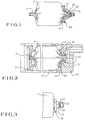
- a film tube 11 is closed at both ends with a clip 12. On one of the two end faces there is a ring 20 between the filled part of the film tube 11 and the clip 12. The ring 20 lies against the film tube with a narrow edge 24. At the edge 24, the ring 20 is also connected to the film tube 11 by adhesive.
- the ring 20 is provided with two tongue-shaped catches 22, which act as a spacer from the clip 12.
- the clip 12 cannot slip inside the ring.
- This facilitates the opening of the film tube 11 by cutting off the closed part of the film tube 11 held together by the clip 12.
- notches 23 are provided in the ring 20 in the area of the spacers 22, which can be attached with scissors or a side cutter to cut open the film tube without the risk of slipping.
- the catches 22 can be pressed resiliently outward and thus allow the ring 20 to be pulled over the closed clamp 12 onto the hose during the manufacture of the packaging, where it is glued on. The sticking prevents the ring 20 from becoming detached from the film tube 11 after being cut open.
- FIG. 2 shows the opened film tube 11 lying in a cylindrical housing 31.
- a conical sealing surface 21 of the ring 20 is in firm, sealing contact with a counter surface 35 of a cap 33 provided on the end face of the housing 31.
- the counter surface 35 surrounds the dispensing opening 34 provided in a cap 33 for the substance located in the film container 11 .
- the contents of the film tube 11 can be discharged by pressure on a piston 32 provided on the other end of the container.
- the ring 20 with its conical sealing surface 21 is pressed against the counter surface 35 and wedged in the cap 33. Because of the small area of the edge 24 tapered onto the film tube 11, a high sealing contact pressure also acts between the ring 20 and the film tube 11 As a result, the content of the film tube 11 can neither between the ring 20 and the cap 33 nor get between the film tube 11 and the ring 20 to the inner wall of the housing.
- the emptied film tube, which is removed from the housing 31 after the piston 32 has been pulled back, is therefore not contaminated on the outside.
- the inner wall of the housing 31 also remains free of contamination from the contents of the film tube 11, which could hinder the movement of the piston 32.
- the ring 20 Since the ring 20 is glued to the film tube 11, it is also removed when the film tube 11 is pulled out. Disposable parts are thus only the film tube 11 with the two clips 12 and the ring 20. Depending on the desired size of the opening of the tube 11, the ring can be made as small as possible so that the amount of waste remains limited.
- Figure 3 shows the partial view of a film tube 11, which is provided with a very small ring 20.
- the inside diameter of this ring is smaller than the outside diameter of the clamp 12.
- the ring 20 In order to be able to attach the ring 20 after the film tube 11 has been closed by the clip 12, in this embodiment it consists of two semi-ring-shaped parts 25 and 26. Both parts are glued or clamped together after being placed on the film tube. Due to the interaction of the conical sealing surface 21 with the counter surface 35, the two ring parts 25 and 26 are pressed tightly together during use, so that the tightness of the connection between the ring parts 25 and 26 is not a problem.
- the absence of the spacer means that the ring 20 is very flat and hardly limits the filling volume of the film tube.
- Figure 4 shows the exploded view of a container for a two-component substance.
- a film tube 11 is provided for each of the components, which is closed with clips 12 as described above and each has a ring 20.
- Each of the film tubes 11 is inserted into one of two cylindrical chambers 47, 48 of a double cylinder 41.
- An end face of the double cylinder 41 is provided with a cap 43 which is provided with a discharge opening 44, 45 for each of the housing chambers 47, 48.
- Both discharge openings 44 and 45 are designed as cranked channels which open into a nozzle 50 lying close to one another.
- a bayonet lock 51, 46 is provided, which can, however, also be replaced by a screw lock.
- a piston 42 is provided for each of the housing chambers 47, 48.
- the latter On the side of the piston 42 facing the film tube, the latter is profiled in such a way that it has recesses in the central region for the clip 12 of the film tube 11 and in the peripheral region for the compressing film of the film tube 11. In this way, the most complete possible application of the substance located in the film tube 11 is made possible.
- the container shown in the disassembled state in FIG. 4 is assembled in FIG. 5 and shown inserted in a dosing gun 60.
- Both pistons 42 are operated together by a single U-shaped piston rod 62.
- the feed takes place step by step by pulling a feed lever 64 against a pistol grip 63.
- the nozzle 50 is thus designed as a static mixer, for example according to EP-A-0 378 806.
- the two discharge openings 44 and 45 open side by side into the nozzle 50.
- the cap 43 is designed in such a way that both discharge openings open concentrically into the nozzle 50.
- the nozzle 50 is also a disposable part.
- the mixing ratio of the two components is 1: 1. With other mixing ratios, different diameters of the film tubes 11 are necessary. This prevents confusion even without color coding.
Abstract
Description
- Die Erfindung betrifft einen Behälter mit Folienschlauch für eine fließfähige Substanz.
- Solche Behälter dienen als Einweg-Verpackungen beispielsweise für Klebstoffe, Dicht- und Formmassen oder andere aushärtbare Substanzen.
- Aus DE-A-3 823 708 sind Behälter für voneinander getrennte pastöse Komponenten bekannt, die in exakt definiertem Mengenverhältnis ausgebracht und einem Mischer zugeführt werden können. Jede Komponente ist dort in einer steifen Kartusche enthalten, die an einer Seite mit einem Austrittsstutzen und an der anderen Seite von einem verschiebbaren Kolben abgeschlossen ist.
- Der bekannte, als feste Kartusche ausgebildete Behälter erlaubt zwar die exakte Dosierung der Komponenten, ist jedoch verhältnismäßig aufwendig und bedarf zur ausreichenden Abdichtung des Kolbens einer toleranzgenauen Fertigung. Außerdem stellen steife Kartuschen als Einwegbehälter bei der Entsorgung ein Problem dar, das zunehmend ernst genommen wird.
- Aus diesen Gründen ist man dazu übergegangen, als Einweg-Verpackungen für fließfähige Substanzen Folienschläuche einzusetzen, die in eine zylindrische Kammer eingelegt werden, in der ihr Inhalt aus dem aufgeschnittenen Schlauch herausgedrückt werden kann. Bei derartigen Behältern ist lediglich der Folienschlauch ein Einwegteil. Er ist in der Herstellung billig und nimmt im entleerten Zustand nur wenig Platz ein. Solche Behälter sind beispielsweise in DE-A-3 826 887, DE-U-8 901 554 und US-A-3 838 796 beschrieben.
- Die bekannten Behälter mit Folienschläuchen haben jedoch den Nachteil, daß die aus dem aufgeschnittenen Folienschlauch austretende Substanz das Innere der zylindrischen Kammer verschmutzt und nach einiger Zeit die Bewegung des Kolbens hemmt und den Behälter unbrauchbar macht. Da ein Teil der Substanz nicht nur durch die Ausbringöffnung entweicht, sondern auch aus dem Folienschlauch in das Innere der zylindrischen Kammer fließt, ist eine exakte Dosierung der Substanz unmöglich. Dies stellt insbesondere bei Substanzen, die eine Komponente eines mit exakten Mengenverhältnissen zu mischenden Stoffes sind, einen schweren Nachteil dar.
- Um diese Nachteile zu vermeiden, verwendet die Firma Teroson für die von ihnen vertriebenen Dichtstoffe eine Schlauchpackung, die auf einer Stirnseite einen außen aufgeklebten Ring aufweist. Dieser Ring ist mit einem Gewinde zur Verbindung mit einem Austrittsstutzen versehen. Der Austrittsstutzen weist Messer auf, die beim Zusammenschrauben aus dem Folienschlauch innerhalb des Rings eine Öffnung herausschneiden. Nach dem Aufschneiden muß der Austrittsstutzen noch einmal abgeschraubt werden, um das herausgeschnittene Folienstück zu entfernen, da es sonst den Austrittsstutzen verstopfen würde. Diese Handhabung ist sehr umständlich und unsauber.
- Eine ähnlich gestaltete und und in der Handhabung ähnlich umständliche Schlauchpackung, die die im ersten Teil des Anspruchs 1 enthaltenen Merkmale aufweist, ist aus DE-A-3 500 625 bekannt.
- Der Erfindung liegt daher die Aufgabe zugrunde, einen Behälter für eine fließfähige Substanz anzugeben, der nur eine geringe Menge an Einweg-Material enthält und dennoch einfach und sauber zu handhaben ist und eine genaue Dosierung der Substanz zuläßt.
- Die erfindungsgemäße Lösung dieser Aufgabe ist in Anspruch 1 angegeben. Demnach ist der Folienschlauch mit einem Ring versehen, der eine konische Dichtfläche aufweist. Eine mit dieser zusammenwirkende ebensolche Dichtfläche umgibt eine in einer starren Kappe des Behälters angebrachte Ausbringöffnung. Zur Verwendung des Behälters wird der Folienschlauch innerhalb des Rings aufgeschnitten und dann so in ein zylindrisches Gehäuse eingesetzt, daß sich die Dichtfläche des Rings gegen die Gegenfläche der starren Kappe schiebt.
- Eine konische Dichtfläche hat den Vorteil, daß sich der Folienschlauch beim Einlegen in das zylindrische Gehäuse automatisch zentriert. Die konische Ausführung der Dichtflächen bewirkt außerdem eine Erhöhung der dichtenden Andruckkraft. Somit wird verhindert, daß die in dem Folienbehälter befindliche Substanz das Gehäuseinnere, insbesondere die Gleitflächen des Kolbens, verschmutzt. Der entleerte Folienbehälter läßt sich problemlos entnehmen, ohne wie bei konventionellen Behältern, bedingt durch die ausgelaufene Substanz, an der Gehäuseinnenwand zu kleben. Die dichtende Funktion des Rings gewährleistet einer präzise Dosierung der Substanz. Außerdem verhindert der Ring, daß der aufgeschnittene Folienbehälter zu weit aufreißt.
- Die Maßnahmen der Ansprüche 2 bis 4 bewirken eine dichte und stabile Befestigung des Rings an dem Folienschlauch.
- Die Weiterbildungen nach den Ansprüchen 5 bis 8 haben den Vorteil, daß die Klammer, die den Folienschlauch verschnürt und verschließt, nicht in den Ring hineinrutschen kann. Der von der Klammer zusammengeschnürte Teil des Folienschlauches läßt sich somit auf einfache Weise mit einem Seitenschneider oder einer Schere zum Öffnen des Schlauches an einer definierten Stelle abschneiden. Dabei verhindert der Ring, daß sich der Folienschlauch zu weit öffnet und der Inhalt vorzeitig ausfließt.
- Vorteilhafte Ausführungsbeispiele der Erfindung werden nachstehend anhand der Zeichnungen näher erläutert. Darin zeigt
- Figur 1
- einen verschlossenen Folienschlauch mit einem als Schnittbild dargestellten Ring,
- Figur 2
- ein Schnittbild eines Behälters, wobei der Folienschlauch aus Gründen der Anschaulichkeit nicht im Schnitt dargestellt ist,
- Figur 3
- eine Teilansicht eines verschlossenen Folienschlauchs mit Ring,
- Figur 4
- ein Schnittbild eines Behälters für eine Zweikomponenen-Substanz, und
- Figur 5
- den in eine Dosierpistole eingelegten Behälter für die Zweikomponenten-Substanz.
- Gemäß Figur 1 ist ein Folienschlauch 11 an beiden Enden jeweils mit einer Klammer 12 verschlossen. An einer der beiden Stirnseiten befindet sich zwischen dem gefüllten Teil des Folienschlauchs 11 und der Klammer 12 ein Ring 20. Der Ring 20 liegt mit einer schmalen Kante 24 am Folienschlauch an. An der Kante 24 ist der Ring 20 außerdem durch Klebstoff mit dem Folienschlauch 11 verbunden.
- Der Ring 20 ist mit zwei zungenförmigen Rasten 22 versehen, die als Abstandshalter zur Klammer 12 wirken. Somit kann die Klammer 12 nicht in das Innere des Rings hineinrutschen. Dies erleichtert das Öffnen des Folienschlauchs 11 durch Abschneiden des von der Klammer 12 zusammengehaltenen, verschlossenen Teils des Folienschlauches 11. Zur bequemen Handhabung sind in dem Ring 20 im Bereich der Abstandshalter 22 Kerben 23 vorgesehen, an denen mit einer Schere oder einem Seitenschneider angesetzt werden kann, um den Folienschlauch aufzuschneiden, ohne daß die Gefahr eines Abrutschens besteht. Die Rasten 22 lassen sich federnd nach außen drücken und erlauben somit, daß der Ring 20 bei der Herstellung der Verpackung über die geschlossene Klammer 12 auf den Schlauch aufgezogen werden kann, wo er festgeklebt wird. Das Festkleben verhindert, daß sich der Ring 20 nach dem Aufschneiden vom Folienschlauch 11 löst.
- Figur 2 zeigt den geöffneten Folienschlauch 11 in einem zylindrischen Gehäuse 31 liegend. Dabei befindet sich eine konische Dichtfläche 21 des Rings 20 in festem, dichtenden Kontakt mit einer Gegenfläche 35 einer an der Stirnseite des Gehäuses 31 vorgesehenen Kappe 33. Die Gegenfläche 35 umgibt die in einer Kappe 33 vorgesehene Ausbringöffnung 34 für die in dem Folienbehälter 11 befindliche Substanz.
- Die Ausbringöffnung 34 ist als gekröpfter Kanal ausgeführt, der es ermöglicht, daß die Substanzen zweier nebeneinander liegender Behälter dieser Bauart in dicht nebeneinander liegenden Kanälen einem (nicht dargestellten) Mischer zugeführt werden. Die gekröpfte Anordnung des Kanals 34 ist somit bei Behältern für Mehrkomponenten-Werkstoffe vorteilhaft.
- Durch Druck auf einen an der anderen Stirnseite des Behälters vorgesehenen Kolben 32 läßt sich der Inhalt des Folienschlauches 11 ausbringen. Dabei wird der Ring 20 mit seiner konischen Dichtfläche 21 gegen die Gegenfläche 35 gedrückt und verkeilt sich in der Kappe 33. Wegen der geringen Fläche der auf den Folienschlauch 11 hin zugespitzten Kante 24 wirkt außerdem ein hoher dichtender Anpreßdruck zwischen dem Ring 20 und dem Folienschlauch 11. Dadurch kann der Inhalt des Folienschlauchs 11 weder zwischen dem Ring 20 und der Kappe 33 noch zwischen dem Folienschlauch 11 und dem Ring 20 hindurch an die Gehaüseinnenwand gelangen. Der entleerte Folienschlauch, der nach Zurückziehen des Kolbens 32 aus dem Gehäuse 31 entnommen wird, ist daher außen nicht verschmutzt. Auch die Innenwand des Gehäuses 31 bleibt frei von Verunreinigungen durch den Inhalt des Folienschlauchs 11, die die Bewegung des Kolbens 32 behindern könnten.
- Da der Ring 20 mit dem Folienschlauch 11 verklebt ist, wird er beim Herausziehen des Folienschlauchs 11 mit entnommen. Wegwerfteile sind somit nur der Folienschlauch 11 mit den beiden Klammern 12 und dem Ring 20. Je nach gewünschter Größe der Öffnung des Schlauchs 11, läßt sich der Ring so klein wie möglich gestalten, so daß die Abfallmenge begrenzt bleibt.
- Figur 3 zeigt die Teilansicht eines Folienschlauchs 11, der mit einem sehr kleinen Ring 20 versehen ist. Der Innendurchmesser dieses Rings ist kleiner als der Außendurchmesser der Klammer 12. Dies macht die Verwendung des in Figur 1 mit 22 bezeichneten Abstandshalters überflüssig. Um den Ring 20 dennoch nach dem Verschließen des Folienschlauchs 11 durch die Klammer 12 anbringen zu können, besteht er in dieser Ausführungsform aus zwei halbringförmigen Teilen 25 und 26. Beide Teile werden nach dem Anlegen an den Folienschlauch miteinander verklebt oder verklemmt. Bedingt durch das Zusammenwirken der konischen Dichtfläche 21 mit der Gegenfläche 35 werden die beiden Ringteile 25 und 26 im Gebrauch fest aneinandergedrückt, so daß die Dichtheit der Verbindung zwischen den Ringteilen 25 und 26 kein Problem darstellt.
- Das Fehlen des Abstandshalters bewirkt, daß der Ring 20 sehr flach ist und das Füllvolumen des Folienschlauches kaum einschränkt.
- Figur 4 zeigt die Explosionsdarstellung eines Behälters für ein Zweikomponenten-Substanz. Für jede der Komponenten ist ein Folienschlauch 11 vorgesehen, der wie oben beschrieben mit Klammern 12 verschlossen ist und jeweils einen Ring 20 aufweist.
- Jeder der Folienschläuche 11 ist in eine von zwei zylindrischen Kammern 47, 48 eines Doppelzylinders 41 eingelegt. An einer Stirnseite des Doppelzylinders 41 ist eine Kappe 43 vorgesehen, die für jede der Gehäusekammern 47, 48 jeweils mit einer Ausbringöffnung 44, 45 versehen ist.
- Beide Ausbringöffnungen 44 und 45 sind als gekröpfte Kanäle ausgebildet, die dicht nebeneinanderliegend in eine Düse 50 münden. Zur Befestigung der Düse 50 an der Kappe 43 ist ein Bajonettverschluß 51, 46 vorgesehen, der jedoch auch durch einen Schraubverschluß ersetzt werden kann.
- Für jede der Gehäusekammern 47, 48 ist ein Kolben 42 vorgesehen. Auf der dem Folienschlauch zugewandten Seite des Kolbens 42 ist dieser so profiliert, daß er Ausnehmungen im Mittelbereich für die Klammer 12 des Folienschlauchs 11 und im Umfangsbereich für die sich zusammendrückende Folie des Folienschlauchs 11 aufweist. So wird ein möglichst vollständiges Ausbringen der im Folienschlauch 11 befindlichen Substanz ermöglicht.
- Der in Figur 4 in zerlegtem Zustand dargestellte Behälter ist in Figur 5 zusammengesetzt und in eine Dosierpistole 60 eingelegt abgebildet.
- Beide Kolben 42 werden gemeinsam von einer einzigen U-förmigen Kolbenstange 62 betätigt. Der Vorschub erfolgt schrittweise durch Ziehen eines Vorschubhebels 64 gegen einen Pistolengriff 63.
- Im Inneren der Düse 50 sind (nicht dargestellt) Mischerflügel angeordnet, die für eine Durchmischung der Zweikomponenten-Substanz beim Durchströmen der Düse 50 sorgen. Die Düse 50 ist somit als statischer Mischer etwa gemäß EP-A-0 378 806 ausgebildet.
- Beim dargestellten Ausführungsbeispiel münden die beiden Ausbringöffnungen 44 und 45 nebeneinander in die Düse 50. Eine bessere Durchmischung der beiden Komponenten läßt sich jedoch erzielen, wenn die Kappe 43 so gestaltet ist, daß beide Ausbringöffnungen konzentrisch in die Düse 50 münden.
- Bei aushärtenden Zweikomponenten-Substanzen ist neben den Folienschläuchen 11 und den Ringen 20 auch die Düse 50 ein Wegwerfteil. Um demgegenüber die Kappe 43 stets wiederverwenden zu können, ist es bei gleich großen Folienschläuchen 11 wie im vorliegenden Ausführungsbeispiel zweckmäßig, die Folienschläuche 11, die Gehäusekammern 47 und 48 und die beiden Hälften der Kappe 43 farblich so zu kennzeichnen, daß der Benutzer jede Komponente der Substanz stets auf der gleichen Seite der Kappe 43 anordnet. So wird vermieden, daß jede Komponente bereits innerhalb der Ausbringöffnungen 44 und 45 in Kontakt mit Resten der anderen Komponente gerät, dadurch aushärtet und die Ausbringöffnungen sowie die Düse 50 verstopft.
- Im vorliegenden Ausführungsbeispiel beträgt das Mischungsverhältnis der beiden Komponenten 1:1. Bei anderen Mischungsverhältnissen sind entsprechend unterschiedliche Durchmesser der Folienschläuche 11 notwendig. Dadurch ist ein Verwechseln auch ohne farbliche Markierung ausgeschlossen.
Claims (8)
- Behälter für fließfähige Substanzen, mit
einem Folienschlauch (11) zur Aufnahme der Substanz,
einem zylindrischen Gehäuse (31; 41) zur Aufnahme des Folienschlauchs (11) zwischen einem verschiebbaren Kolben (32; 42) und einer starren, eine Ausbringöffnung (34; 44, 45) aufweisenden Kappe (33; 43), und
einem an der der Kappe (33; 43) zugewandten Stirnseite des Folienschlauchs (11) befestigten Ring (20),
dadurch gekennzeichnet, daß der Ring (20) eine konische Dichtfläche (21) und die Kappe (33; 43) eine mit dieser zusammenwirkende und die Ausbringöffnung (34; 44, 45) umgebende, ebenso konische Gegenfläche (35) aufweist. - Behälter nach Anspruch 1, wobei der Ring (20) auf dem Folienschlauch (11) dichtend aufgeklebt ist.
- Behälter nach Anspruch 1 oder 2, wobei der Ring (20) eine umlaufende Dichtkante (24) zur Abdichtung mit dem Folienschlauch (11) aufweist.
- Behälter nach Anspruch 3, wobei die Dichtkante (24) auf den Folienschlauch (11) hin zugespitzt ist.
- Behälter nach einem der Ansprüche 1 bis 4, wobei der Folienschlauch (11) mit einer Klammer (12) verschlossen und der Ring (20) mit einem Abstandshalter (22) versehen ist, dessen Innenmaß kleiner ist als das Außenmaß der Klammer (12).
- Behälter nach Anspruch 5, wobei der Abstandshalter (22) als federnde Raste ausgebildet ist, die das Aufziehen des Rings (20) auf den Folienschlauch (11) über die Klammer (12) hinweg gestattet, ein Zurückrutschen jedoch verhindert.
- Behälter nach Anspruch 5 oder 6, wobei der Abstandshalter (22) an der Stelle, an der der Folienschlauch (11) durch Abschneiden des von der Klammer (12) verschlossenen Teils geöffnet werden kann, mit einer Kerbe (23) versehen ist.
- Behälter nach einem der Ansprüche 1 bis 7, wobei der Ring (20) aus zwei Halbringen (25, 26) zusammengesetzt ist.
Applications Claiming Priority (4)
| Application Number | Priority Date | Filing Date | Title |
|---|---|---|---|
| DE9114084 | 1991-11-12 | ||
| DE9114084U | 1991-11-12 | ||
| DE9200521U DE9200521U1 (de) | 1991-11-12 | 1992-01-17 | |
| DE9200521U | 1992-01-17 |
Publications (2)
| Publication Number | Publication Date |
|---|---|
| EP0541972A1 true EP0541972A1 (de) | 1993-05-19 |
| EP0541972B1 EP0541972B1 (de) | 2000-09-27 |
Family
ID=25958838
Family Applications (1)
| Application Number | Title | Priority Date | Filing Date |
|---|---|---|---|
| EP92117405A Expired - Lifetime EP0541972B1 (de) | 1991-11-12 | 1992-10-12 | Behälter für fliessfähige Substanzen |
Country Status (16)
| Country | Link |
|---|---|
| US (2) | US5332122A (de) |
| EP (1) | EP0541972B1 (de) |
| JP (1) | JP3355208B2 (de) |
| AT (1) | ATE196626T1 (de) |
| AU (1) | AU652675B2 (de) |
| BR (1) | BR9204356A (de) |
| CA (1) | CA2081760C (de) |
| CZ (1) | CZ282440B6 (de) |
| DE (2) | DE9200521U1 (de) |
| DK (1) | DK0541972T3 (de) |
| ES (1) | ES2151478T3 (de) |
| FI (1) | FI107720B (de) |
| HU (1) | HU215250B (de) |
| MX (1) | MX9206424A (de) |
| NO (1) | NO924325L (de) |
| PL (1) | PL168466B1 (de) |
Cited By (34)
| Publication number | Priority date | Publication date | Assignee | Title |
|---|---|---|---|---|
| WO1995005984A2 (en) * | 1993-08-20 | 1995-03-02 | Keller Wilhelm A | Multiple component metering and relative proportioning device with collapsible cartridge |
| EP0663348A1 (de) * | 1994-01-13 | 1995-07-19 | THERA Patent GmbH & Co. KG Gesellschaft für industrielle Schutzrechte | Vorrichtung zum Entleeren eines Schlauchbeutels |
| EP0665063A1 (de) * | 1994-01-26 | 1995-08-02 | Ciba-Geigy Ag | Apparat zum Spenden von zwei Komponenten |
| BE1008472A3 (fr) * | 1994-07-05 | 1996-05-07 | Mertens De Wilmars Antoon | Conditionnement pour colles a deux composants et dispositif pour l'application de ces colles. |
| EP0754633A2 (de) * | 1995-07-19 | 1997-01-22 | Exchem plc | Mehrkammmerkartusche zur Verwendung in wiederverwendbarer Abgabevorrichtung |
| GB2305160A (en) * | 1992-12-22 | 1997-04-02 | Hosokawa Yoko Kk | Flexible container for use with discharge gun |
| WO1997026201A1 (en) * | 1996-01-18 | 1997-07-24 | The Procter & Gamble Company | Inverting bag co-dispenser |
| US5667102A (en) * | 1994-07-18 | 1997-09-16 | Keller; Wilhelm A. | Cartridge with an exchangeable content package |
| WO1998017548A1 (en) * | 1996-10-22 | 1998-04-30 | Develey Feinkostfabrik Gmbh | Method of expressing paste-like substances, particularly foodstuffs, disposed in containers and device usable for said purpose |
| WO1998044860A1 (de) | 1997-04-08 | 1998-10-15 | Ernst Mühlbauer KG | Anordnung zum ausgeben einer gemischten dentaltechnischen mehrkomponentenmasse |
| EP0910995A2 (de) | 1997-10-15 | 1999-04-28 | zwingenberger, Arthur | Dentales Handgerät zum Mischen und Ausbringen einer Mehrkomponenten-Formmasse |
| EP0976458A2 (de) | 1998-07-31 | 2000-02-02 | VOCO GmbH | Anordnung zur Ausgabe von fliessfähigen Substanzen aus Folienschläuchen |
| EP0992438A1 (de) * | 1998-10-09 | 2000-04-12 | Wilhelm A. Keller | Dünnwandige Kartusche für wiederverwendbare Abgabevorrichtung |
| US6311871B1 (en) * | 1998-11-04 | 2001-11-06 | Kress-Elektrik Gmbh & Co. | Device for pressing out and dispensing dosed quantities of flowable multiple-component compounds |
| DE10112904A1 (de) * | 2001-03-15 | 2002-10-02 | 3M Espe Ag | Dynamischer Mischer |
| WO2002049938A3 (de) * | 2000-12-21 | 2002-11-07 | Wacker Chemie Gmbh | Dosiervorrichtungsaufsatz |
| EP1738737A1 (de) | 2005-07-01 | 2007-01-03 | Kettenbach GmbH & CO. KG | Zu formstabilen Formkörpern aushärtendes kondensationsvernetzendes Dentalmaterial |
| DE4343985B4 (de) * | 1992-12-22 | 2007-10-18 | Kabushiki Kaisha Hosokawa Yoko | Behälter und Verfahren zum Herstellen eines Behälters |
| EP1849529A1 (de) * | 2006-04-25 | 2007-10-31 | Exchem plc | Kartusche |
| US7320541B2 (en) | 2003-08-14 | 2008-01-22 | 3M Espe Ag | Mixer element for a mixer for multi-component pastes, and mixer using the same |
| US7498363B2 (en) | 2004-09-17 | 2009-03-03 | Kettenbach Gmbh & Co. Kg | Two-component dental molding material made of hydroxyl-functional polyethers and alkoxysilanes or silicic acid esters |
| US7504442B2 (en) | 2004-09-17 | 2009-03-17 | Kettenbach Gmbh & Co. Kg | Condensation-crosslinking two-component dental molding material made of alkoxysilyl- and hydroxysilyl-functional polyethers |
| DE102008014773A1 (de) | 2008-03-18 | 2009-10-08 | Delo Industrieklebstoffe Gmbh & Co. Kg | Behälter für fließfähige Substanzen |
| CH699388A1 (de) * | 2008-08-18 | 2010-02-26 | Mungo Befestigungstech Ag | Klemmverschluss für eine Kartusche, Adapter sowie Kartusche. |
| DE102009021553A1 (de) | 2009-05-09 | 2010-11-18 | Kettenbach Gmbh & Co. Kg | Härtbare Zusammensetzungen, daraus hergestellte gehärtete Produkte und deren Verwendung |
| US7902269B2 (en) | 2004-02-13 | 2011-03-08 | Kettenbach Gmbh & Co. Kg | Dental material based on alkoxysilyl-functional polyethers containing a salt of a strong base as catalyst |
| WO2012010859A1 (en) | 2010-07-19 | 2012-01-26 | 2K Polymer Systems Limited | Multi-component dispenser |
| DE102010046697A1 (de) | 2010-09-28 | 2012-03-29 | Kettenbach Gmbh & Co. Kg | Polymerisierbares Dentalmaterial mit Reaktiv-Pastenbildner, gehärtetes Dentalmaterial und deren Verwendung |
| US8147122B2 (en) | 2003-03-06 | 2012-04-03 | Dentsply International Inc. | Dispensing and mixing tip for reactive componets |
| WO2014033280A2 (de) | 2012-08-31 | 2014-03-06 | Kettenbach Gmbh & Co. Kg | Radikalisch polymerisierbares dentalmaterial, gehärtetes produkt und verwendung |
| US9517488B2 (en) | 2004-12-30 | 2016-12-13 | Plas-Pak Industries, Inc. | Component delivery system utilizing film bags |
| EP3251756A1 (de) * | 2016-05-31 | 2017-12-06 | Sulzer Mixpac AG | Gehäuse und spender |
| US10625293B2 (en) | 2004-12-30 | 2020-04-21 | Nordson Corporation | Component delivery system utilizing film bags |
| DE102022111589A1 (de) | 2022-05-10 | 2023-11-16 | DPH Dental Works GmbH | Dynamischer Mischer, Anordnungen mit einem solchen Mischer und Verfahren zum Mischen mit einem solchen Mischer |
Families Citing this family (66)
| Publication number | Priority date | Publication date | Assignee | Title |
|---|---|---|---|---|
| US5289949A (en) * | 1992-06-22 | 1994-03-01 | Chesebrough-Pond's Usa Co., Division Of Conopco, Inc. | Multi-cavity dispensing refill cartridge |
| DE4311876A1 (de) * | 1993-04-10 | 1994-10-13 | Hilti Ag | Kolben für Auspressgeräte |
| DE4327755C2 (de) * | 1993-08-18 | 1999-02-11 | Upat Max Langensiepen Kg | Kartusche für Zweikomponentenmassen |
| US5386928A (en) * | 1993-11-15 | 1995-02-07 | Minnesota Mining And Manufacturing Company | Dual collapsible tube dispensing assembly |
| US5816445A (en) * | 1996-01-25 | 1998-10-06 | Stainless Steel Coatings, Inc. | Method of and apparatus for controlled dispensing of two-part bonding, casting and similar fluids and the like |
| DE29606463U1 (de) * | 1996-04-09 | 1997-08-07 | Thera Ges Fuer Patente | Vorrichtung zum Entleeren eines Schlauchbeutels |
| WO1998006505A1 (de) * | 1996-08-12 | 1998-02-19 | Muehlbauer Ernst | Anordnung zum auspressen einer fliessfähigen substanz aus einem schlauchbeutel |
| US5873490A (en) * | 1996-12-09 | 1999-02-23 | Walpole; Geary A. | Flowable substance dispenser |
| ES2270400T3 (es) * | 1996-12-24 | 2007-04-01 | Mixpac Systems Ag | Un dispositivo para el uso de un envase de paredes delgadas. |
| US5873492A (en) * | 1997-01-28 | 1999-02-23 | Coltene/Whaledent, Inc. | Dispensing bag for dynamic mixer |
| DE29705488U1 (de) * | 1997-03-26 | 1998-07-23 | Thera Ges Fuer Patente | Vorrichtung zum Entleeren eines Schlauchbeutels |
| WO1999026727A1 (fr) * | 1997-11-25 | 1999-06-03 | Cemedine Co., Ltd. | Mecanisme a extrusion |
| DE19806869A1 (de) * | 1998-02-19 | 1999-08-26 | Focke & Co | Vorrichtung zum Auftragen von Leim |
| EP0941941B1 (de) | 1998-03-03 | 2006-02-22 | Sicpa Holding S.A. | Gehäuse, das eine auswechselbare flexible Verpackungseinheit enthält |
| US6644509B1 (en) * | 1999-04-12 | 2003-11-11 | Kettenbach Gmbh & Co. Kg | Film packaging for a pasty-like substance |
| US20050255425A1 (en) * | 2000-09-21 | 2005-11-17 | Pierson Paul R | Mixing tip for dental materials |
| US6863178B2 (en) * | 2000-12-05 | 2005-03-08 | Daisy Brand, Inc. | Packet container |
| US7041084B2 (en) * | 2001-05-24 | 2006-05-09 | Fojtik Shawn P | Hand-held, hand operated power syringe and methods |
| WO2003097157A1 (en) * | 2002-05-17 | 2003-11-27 | Tyco Healthcare Group, Lp | Wound closure material applicator |
| GB0304351D0 (en) * | 2003-02-26 | 2003-04-02 | Wood Bruce M | Chemical dispensing means |
| ATE321501T1 (de) * | 2003-06-18 | 2006-04-15 | 3M Espe Ag | Austragkartusche |
| EP1588779A1 (de) * | 2004-04-19 | 2005-10-26 | 3M Espe AG | Dynamischer Mischer |
| US8322909B2 (en) | 2004-09-22 | 2012-12-04 | 3M Deutschland Gmbh | Mixer for multi-component pastes, kit, and method of mixing paste components |
| EP1640060A1 (de) | 2004-09-22 | 2006-03-29 | 3M Espe Ag | Mischer für Mehrkomponentenpasten, Bausatz, und Verfahren zum Mischen von Pasten |
| US20060065132A1 (en) * | 2004-09-27 | 2006-03-30 | Conopco, Inc., D/B/A Unilever Foodsolutions | Combined food product and package |
| JP4670302B2 (ja) * | 2004-10-06 | 2011-04-13 | 株式会社スリーボンド | 材料圧送装置 |
| DE102006001126A1 (de) | 2006-01-09 | 2007-07-12 | Kettenbach Gmbh & Co. Kg | Dentalabformmassen, daraus hergestellte gehärtete Produkte und Verwendung von Tensiden zur Herstellung von Dentalabformmassen |
| GB0602340D0 (en) * | 2006-02-07 | 2006-03-15 | Rawlplug Co Ltd | Nozzle and/or adaptor unit on cartridge |
| US7534234B2 (en) * | 2006-05-09 | 2009-05-19 | Fojtik Shawn P | Hand-held aspiration syringe and methods |
| US20080142546A1 (en) * | 2006-12-15 | 2008-06-19 | Conopco, Inc., D/B/A Unilever | Package |
| JP5406035B2 (ja) | 2006-12-15 | 2014-02-05 | スリーエム イノベイティブ プロパティズ カンパニー | 硬化性多成分材料の混合及び吐出 |
| US20080142545A1 (en) * | 2006-12-15 | 2008-06-19 | Conopco, Inc., D/B/A Unilever | Package |
| EP2044923A1 (de) | 2007-10-04 | 2009-04-08 | 3M Innovative Properties Company | Dentalzusammensetzung mit Glaskügelchen sowie Herstellungs- und Verwendungsverfahren dafür |
| CN101938972B (zh) | 2007-12-18 | 2013-03-27 | 3M创新有限公司 | 含表面活性剂和含氟化合物的牙科用组合物及其制备和使用方法 |
| EP2072030A1 (de) | 2007-12-20 | 2009-06-24 | 3M Innovative Properties Company | Zahnabdruckmaterial mit rheologischen Modifikationen |
| DE102008005743A1 (de) * | 2008-01-23 | 2009-08-06 | Heraeus Kulzer Gmbh | Vorrichtung zur Lagerung von fluiden Komponenten für den dentalen Bereich |
| DE102008001658A1 (de) * | 2008-05-08 | 2009-11-12 | Hilti Aktiengesellschaft | Foliengebinde mit nebeneinander angeordneten Folienbeuteln |
| DE102008043538A1 (de) * | 2008-11-07 | 2010-05-12 | Hilti Aktiengesellschaft | Auspressvorrichtung |
| EP2266526A1 (de) | 2009-06-15 | 2010-12-29 | 3M Innovative Properties Company | Polyethergruppe enthaltende Dentalzusammensetzung, die eine F enthaltende Verbindung enthält, Verfahren zu deren Herstellung und deren Verwendung |
| WO2011016977A1 (en) | 2009-07-28 | 2011-02-10 | 3M Innovative Properties Company | Cationically hardenable dental composition, process of production and use thereof |
| JP2011057233A (ja) * | 2009-09-07 | 2011-03-24 | Cemedine Co Ltd | 湿気硬化性ペースト状物品包装体の製造方法及び湿気硬化性ペースト状物品包装体 |
| EP2380925A1 (de) | 2010-04-22 | 2011-10-26 | 3M Innovative Properties Company | Strahlungshärtbare Zusammensetzung, Herstellungsverfahren dafür und Verwendung |
| EP2382941A1 (de) * | 2010-04-29 | 2011-11-02 | 3M Innovative Properties Company | System mit einer Misch- und Ausgabevorrichtung und Materialbehälter |
| EP2428199A1 (de) | 2010-09-09 | 2012-03-14 | 3M Innovative Properties Company | Härtbare Zusammensetzung, derer Herstellungsverfahren und Verwendung |
| WO2012067801A1 (en) * | 2010-11-15 | 2012-05-24 | Milwaukee Electric Tool Corporation | Powered dispensing tool |
| EP2468416A1 (de) * | 2010-12-24 | 2012-06-27 | Sika Technology AG | Applikationsvorrichtung für Mehrkomponentenstoffe, ein Kartuschenset und eine Verpackungseinheit |
| RU2600355C2 (ru) | 2011-06-08 | 2016-10-20 | 3М Инновейтив Пропертиз Компани | Композиция, содержащая силоксановые соединения, способ ее получения и использования |
| EP2741729B1 (de) | 2011-08-12 | 2021-11-03 | 3M Innovative Properties Company | Härtbare zusammensetzung mit verkürzter einstellungszeit, herstellungsverfahren dafür und verwendung |
| DE102012218551B3 (de) * | 2012-10-11 | 2014-02-13 | Hilti Aktiengesellschaft | Verfahren zur Herstellung eines Foliengebindes für ein Auspressgerät mit vorbefülltem Kopfteil |
| US9067711B2 (en) | 2012-11-06 | 2015-06-30 | Sonoco Development, Inc. | Storage and dispensing device |
| WO2014130603A1 (en) | 2013-02-25 | 2014-08-28 | 3M Innovative Properties Company | Stabilized dental impression composition, kit of parts and use thereof |
| US9527106B2 (en) * | 2013-10-31 | 2016-12-27 | Nordson Corporation | Applicator and method for dispensing a viscous fluid |
| EP2927156A1 (de) * | 2014-03-31 | 2015-10-07 | Sulzer Mixpac AG | Kartusche und Verfahren zum Herstellen einer Kartusche |
| WO2016099910A1 (en) | 2014-12-16 | 2016-06-23 | 3M Innovative Properties Company | Hardenable dental impression composition comprising a polymeric filler particles and use thereof |
| EP3233018A1 (de) | 2014-12-16 | 2017-10-25 | 3M Innovative Properties Company | Kationisch härtbare dentale zusammensetzung mit polymerpartikeln und verwendung davon |
| US10166570B1 (en) * | 2015-04-15 | 2019-01-01 | Patent & Investment Llc | Applicator system for extrusive dispensing of work material from collapsible cartridge |
| EP3195941A1 (de) * | 2016-01-20 | 2017-07-26 | HILTI Aktiengesellschaft | Auspressvorrichtung für ein foliengebinde, foliengebinde sowie baugruppe aus einer auspressvorrichtung und einem foliengebinde |
| US10968031B2 (en) * | 2017-12-27 | 2021-04-06 | Sulzer Mixpac Ag | Piston for a collapsible cartridge |
| US20200070189A1 (en) * | 2018-08-30 | 2020-03-05 | Nordson Corporation | Adapter mixer attachment |
| WO2020104889A1 (en) | 2018-11-20 | 2020-05-28 | 3M Innovative Properties Company | Curable composition containing a polyether-modified polydimethyl siloxane |
| KR200492453Y1 (ko) * | 2018-12-27 | 2020-10-15 | 주식회사 다우기업 | 리필용 구리스 충전용기 |
| EP3834951A1 (de) * | 2019-12-13 | 2021-06-16 | Hilti Aktiengesellschaft | Kartusche für eine auspressvorrichtung |
| US11896993B2 (en) * | 2020-07-24 | 2024-02-13 | Albion Engineering Company | Common head having an offset partition for use with multi-component dispensing tools and a tubular liner arranged for locating within the common head |
| USD996980S1 (en) | 2021-03-01 | 2023-08-29 | Medmix Switzerland Ag | Cartridge |
| EP4052798A1 (de) * | 2021-03-01 | 2022-09-07 | medmix Switzerland AG | Spender, kartuschenanordnung, trägerhülse und verfahren zur bedienung eines spenders |
| WO2022248954A1 (en) | 2021-05-26 | 2022-12-01 | 3M Innovative Properties Company | Dental composition comprising an isorbide component |
Citations (5)
| Publication number | Priority date | Publication date | Assignee | Title |
|---|---|---|---|---|
| FR750742A (fr) * | 1933-01-04 | 1933-08-17 | Système de tube pouvant servir à alimenter en produits pâteux un appareil à brosse à manche creux | |
| FR1161905A (fr) * | 1956-11-21 | 1958-09-08 | Dispositif de conditionnement des produits pâteux, liquides..., en tubes ou étuis souples sous enveloppes rigides, et de commande pour expulser ces produits | |
| DE3500625A1 (de) * | 1984-01-11 | 1985-08-29 | Knieriem, Günter, Dipl.-Ing. (FH), 6802 Ladenburg | Schlauchbeutel-packung |
| GB2210412A (en) * | 1987-10-02 | 1989-06-07 | Bostik Ltd | Applicators for hot melt materials |
| EP0319666A1 (de) * | 1987-10-07 | 1989-06-14 | Günther Dipl.-Ing. Knieriem | Schlauchbeutel - Packung |
Family Cites Families (14)
| Publication number | Priority date | Publication date | Assignee | Title |
|---|---|---|---|---|
| FR2134871A6 (en) * | 1971-04-23 | 1972-12-08 | Filleul Andre | Rechargeable dispenser - using refill sachets of welded polyester film |
| US3838796A (en) * | 1972-11-21 | 1974-10-01 | M Cohen | Fluid and paste dispenser |
| DE7419062U (de) * | 1974-06-01 | 1975-12-18 | Eppler B | Pastenspender insbesondere fuer zahnpasta |
| US3974943A (en) * | 1975-04-09 | 1976-08-17 | Arthur Lloyd Wilston | Paste dispensing device |
| NL7512255A (en) * | 1975-10-20 | 1977-04-22 | Philips Nv | Aerosol container has housing for propellant - containing replaceable flexible wall vessel for substance to be sprayed |
| US4231492A (en) * | 1978-03-14 | 1980-11-04 | Oatey Co. | Apparatus and method for dispensing putty-like material |
| US4176754A (en) * | 1978-06-23 | 1979-12-04 | Diane Miller | Pneumatic biasing device for preventing air from entering a nursing bottle |
| JPS57127467A (en) * | 1981-01-31 | 1982-08-07 | Toray Silicone Co Ltd | Calking gun for bagged sealing material |
| DE8714014U1 (de) * | 1987-10-19 | 1987-12-23 | Van Leer Verpackungen Gmbh, 5000 Koeln, De | |
| DE3823708C2 (de) * | 1988-07-13 | 1994-04-14 | Atlas Copco Elektrowerkzeuge | Motorisch angetriebene Einrichtung zum Dosieren und Mischen von wenigstens zwei Substanzen |
| DE3826887A1 (de) * | 1988-08-08 | 1990-02-15 | Niedecker Herbert | Schlauchfoermige verpackung aus flexiblem material fuer pastoese massen |
| DE8900469U1 (de) * | 1989-01-17 | 1990-05-23 | Espe Stiftung & Co Produktions- Und Vertriebs Kg, 8031 Seefeld, De | |
| DE8901554U1 (de) * | 1989-02-10 | 1989-06-08 | Ritter, Franz Peter, Ing.(Grad.), 8933 Untermeitingen, De | |
| EP0441538A3 (en) * | 1990-02-03 | 1992-06-03 | The Rawlplug Company Limited | Dispensing apparatus |
-
1992
- 1992-01-17 DE DE9200521U patent/DE9200521U1/de not_active Expired - Lifetime
- 1992-10-12 AT AT92117405T patent/ATE196626T1/de not_active IP Right Cessation
- 1992-10-12 DE DE59209868T patent/DE59209868D1/de not_active Expired - Fee Related
- 1992-10-12 EP EP92117405A patent/EP0541972B1/de not_active Expired - Lifetime
- 1992-10-12 DK DK92117405T patent/DK0541972T3/da active
- 1992-10-12 ES ES92117405T patent/ES2151478T3/es not_active Expired - Lifetime
- 1992-10-26 AU AU27336/92A patent/AU652675B2/en not_active Ceased
- 1992-10-27 FI FI924866A patent/FI107720B/fi not_active IP Right Cessation
- 1992-10-29 CA CA002081760A patent/CA2081760C/en not_active Expired - Fee Related
- 1992-10-29 PL PL92296406A patent/PL168466B1/pl not_active IP Right Cessation
- 1992-11-05 JP JP29600492A patent/JP3355208B2/ja not_active Expired - Fee Related
- 1992-11-05 US US07/971,551 patent/US5332122A/en not_active Expired - Lifetime
- 1992-11-06 HU HU9203492A patent/HU215250B/hu not_active IP Right Cessation
- 1992-11-09 MX MX9206424A patent/MX9206424A/es unknown
- 1992-11-10 BR BR929204356A patent/BR9204356A/pt not_active Application Discontinuation
- 1992-11-10 NO NO92924325A patent/NO924325L/no unknown
- 1992-11-11 CZ CS923365A patent/CZ282440B6/cs not_active IP Right Cessation
-
1994
- 1994-03-07 US US08/206,928 patent/US5419460A/en not_active Expired - Lifetime
Patent Citations (5)
| Publication number | Priority date | Publication date | Assignee | Title |
|---|---|---|---|---|
| FR750742A (fr) * | 1933-01-04 | 1933-08-17 | Système de tube pouvant servir à alimenter en produits pâteux un appareil à brosse à manche creux | |
| FR1161905A (fr) * | 1956-11-21 | 1958-09-08 | Dispositif de conditionnement des produits pâteux, liquides..., en tubes ou étuis souples sous enveloppes rigides, et de commande pour expulser ces produits | |
| DE3500625A1 (de) * | 1984-01-11 | 1985-08-29 | Knieriem, Günter, Dipl.-Ing. (FH), 6802 Ladenburg | Schlauchbeutel-packung |
| GB2210412A (en) * | 1987-10-02 | 1989-06-07 | Bostik Ltd | Applicators for hot melt materials |
| EP0319666A1 (de) * | 1987-10-07 | 1989-06-14 | Günther Dipl.-Ing. Knieriem | Schlauchbeutel - Packung |
Cited By (62)
| Publication number | Priority date | Publication date | Assignee | Title |
|---|---|---|---|---|
| DE4343985B4 (de) * | 1992-12-22 | 2007-10-18 | Kabushiki Kaisha Hosokawa Yoko | Behälter und Verfahren zum Herstellen eines Behälters |
| GB2305160A (en) * | 1992-12-22 | 1997-04-02 | Hosokawa Yoko Kk | Flexible container for use with discharge gun |
| GB2305160B (en) * | 1992-12-22 | 1997-06-25 | Hosokawa Yoko Kk | A container and a method of manufacturing the same |
| WO1995005984A3 (en) * | 1993-08-20 | 1995-04-20 | Wilhelm A Keller | Multiple component metering and relative proportioning device with collapsible cartridge |
| WO1995005984A2 (en) * | 1993-08-20 | 1995-03-02 | Keller Wilhelm A | Multiple component metering and relative proportioning device with collapsible cartridge |
| US5647510A (en) * | 1993-08-20 | 1997-07-15 | Keller; Wilhelm A. | Multiple component metering and relative proportioning device with collapsible cartridge |
| EP0663348A1 (de) * | 1994-01-13 | 1995-07-19 | THERA Patent GmbH & Co. KG Gesellschaft für industrielle Schutzrechte | Vorrichtung zum Entleeren eines Schlauchbeutels |
| EP0665063A1 (de) * | 1994-01-26 | 1995-08-02 | Ciba-Geigy Ag | Apparat zum Spenden von zwei Komponenten |
| US5897028A (en) * | 1994-01-26 | 1999-04-27 | Ciba Specialty Chemicals Corporation | Two component adhesive dispensing unit |
| BE1008472A3 (fr) * | 1994-07-05 | 1996-05-07 | Mertens De Wilmars Antoon | Conditionnement pour colles a deux composants et dispositif pour l'application de ces colles. |
| US5667102A (en) * | 1994-07-18 | 1997-09-16 | Keller; Wilhelm A. | Cartridge with an exchangeable content package |
| EP0754633A3 (de) * | 1995-07-19 | 1997-03-19 | Exchem Plc | Mehrkammmerkartusche zur Verwendung in wiederverwendbarer Abgabevorrichtung |
| EP0787661A1 (de) * | 1995-07-19 | 1997-08-06 | Exchem plc | Wiederverwendbare Abgabevorrichtung |
| EP0754633A2 (de) * | 1995-07-19 | 1997-01-22 | Exchem plc | Mehrkammmerkartusche zur Verwendung in wiederverwendbarer Abgabevorrichtung |
| WO1997026201A1 (en) * | 1996-01-18 | 1997-07-24 | The Procter & Gamble Company | Inverting bag co-dispenser |
| WO1998017548A1 (en) * | 1996-10-22 | 1998-04-30 | Develey Feinkostfabrik Gmbh | Method of expressing paste-like substances, particularly foodstuffs, disposed in containers and device usable for said purpose |
| WO1998044860A1 (de) | 1997-04-08 | 1998-10-15 | Ernst Mühlbauer KG | Anordnung zum ausgeben einer gemischten dentaltechnischen mehrkomponentenmasse |
| US6048201A (en) * | 1997-10-15 | 2000-04-11 | Zwingenberger; Arthur | Arrangement for mixing and delivering a multicomponent molding compound |
| EP0910995A2 (de) | 1997-10-15 | 1999-04-28 | zwingenberger, Arthur | Dentales Handgerät zum Mischen und Ausbringen einer Mehrkomponenten-Formmasse |
| EP0976458A2 (de) | 1998-07-31 | 2000-02-02 | VOCO GmbH | Anordnung zur Ausgabe von fliessfähigen Substanzen aus Folienschläuchen |
| EP0992438A1 (de) * | 1998-10-09 | 2000-04-12 | Wilhelm A. Keller | Dünnwandige Kartusche für wiederverwendbare Abgabevorrichtung |
| WO2000021858A1 (en) * | 1998-10-09 | 2000-04-20 | Keller Wilhelm A | Thin wall package for use within a reusable cartridge |
| US6766921B2 (en) | 1998-10-09 | 2004-07-27 | Mixpac Systems Ag | Thin wall package for use within a reusable cartridge |
| US6578738B1 (en) | 1998-10-09 | 2003-06-17 | Wilhelm A. Keller | Thin wall package for use within a reusable cartridge |
| EP1350736A1 (de) * | 1998-10-09 | 2003-10-08 | Wilhelm A. Keller | Dünnwandige Kartusche für wiederverwendbare Abgabevorrichtung |
| US6311871B1 (en) * | 1998-11-04 | 2001-11-06 | Kress-Elektrik Gmbh & Co. | Device for pressing out and dispensing dosed quantities of flowable multiple-component compounds |
| WO2002049938A3 (de) * | 2000-12-21 | 2002-11-07 | Wacker Chemie Gmbh | Dosiervorrichtungsaufsatz |
| US7287898B2 (en) | 2001-03-15 | 2007-10-30 | 3M Espe Ag | Dynamic mixer |
| DE10112904B4 (de) * | 2001-03-15 | 2004-07-22 | 3M Espe Ag | Dynamischer Mischer und Verfahren zum Mischen von mindestens zwei Pastenkomponenten |
| DE10112904A1 (de) * | 2001-03-15 | 2002-10-02 | 3M Espe Ag | Dynamischer Mischer |
| DE10112904C5 (de) * | 2001-03-15 | 2010-04-22 | 3M Espe Ag | Dynamischer Mischer und Verfahren zum Mischen von mindestens zwei Pastenkomponenten |
| US7674033B2 (en) | 2001-03-15 | 2010-03-09 | 3M Espe Ag | Dynamic mixer |
| US8147122B2 (en) | 2003-03-06 | 2012-04-03 | Dentsply International Inc. | Dispensing and mixing tip for reactive componets |
| US7320541B2 (en) | 2003-08-14 | 2008-01-22 | 3M Espe Ag | Mixer element for a mixer for multi-component pastes, and mixer using the same |
| US7902269B2 (en) | 2004-02-13 | 2011-03-08 | Kettenbach Gmbh & Co. Kg | Dental material based on alkoxysilyl-functional polyethers containing a salt of a strong base as catalyst |
| US7504442B2 (en) | 2004-09-17 | 2009-03-17 | Kettenbach Gmbh & Co. Kg | Condensation-crosslinking two-component dental molding material made of alkoxysilyl- and hydroxysilyl-functional polyethers |
| US7498363B2 (en) | 2004-09-17 | 2009-03-03 | Kettenbach Gmbh & Co. Kg | Two-component dental molding material made of hydroxyl-functional polyethers and alkoxysilanes or silicic acid esters |
| US10625293B2 (en) | 2004-12-30 | 2020-04-21 | Nordson Corporation | Component delivery system utilizing film bags |
| US9968959B2 (en) | 2004-12-30 | 2018-05-15 | Nordson Corporation | Component delivery system utilizing film bags |
| US9517488B2 (en) | 2004-12-30 | 2016-12-13 | Plas-Pak Industries, Inc. | Component delivery system utilizing film bags |
| US10525500B2 (en) | 2004-12-30 | 2020-01-07 | Nordson Corporation | Component delivery system utilizing film bags |
| EP1738737A1 (de) | 2005-07-01 | 2007-01-03 | Kettenbach GmbH & CO. KG | Zu formstabilen Formkörpern aushärtendes kondensationsvernetzendes Dentalmaterial |
| US7790781B2 (en) | 2005-07-01 | 2010-09-07 | Kettenbach Gmbh & Co. Kg | Condensation-crosslinkable dental material hardening to dimensionally stable casts |
| EP1849529A1 (de) * | 2006-04-25 | 2007-10-31 | Exchem plc | Kartusche |
| EP2161216A1 (de) | 2008-03-18 | 2010-03-10 | Delo Industrieklebstoffe Gmbh & Co. Kg Aa | Behälter für fließfähige Substanzen und Verfahren zum blasenfreien Dosieren solcher Substanzen |
| DE102008014773A1 (de) | 2008-03-18 | 2009-10-08 | Delo Industrieklebstoffe Gmbh & Co. Kg | Behälter für fließfähige Substanzen |
| US8955720B2 (en) | 2008-03-18 | 2015-02-17 | DELO Industrieklebstoffe GmbH & Co. KGaA | Container for flowable substances and dispensing apparatus |
| CH699388A1 (de) * | 2008-08-18 | 2010-02-26 | Mungo Befestigungstech Ag | Klemmverschluss für eine Kartusche, Adapter sowie Kartusche. |
| EP2253302A2 (de) | 2009-05-09 | 2010-11-24 | Kettenbach GmbH & CO. KG | Härtbare Zusammensetzungen, daraus hergestellte gehärtete Produkte und deren Verwendung |
| US8614262B2 (en) | 2009-05-09 | 2013-12-24 | Kettenbach Gmbh & Co. Kg | Curable compositions, cured products produced therefrom and use thereof |
| DE102009021553A1 (de) | 2009-05-09 | 2010-11-18 | Kettenbach Gmbh & Co. Kg | Härtbare Zusammensetzungen, daraus hergestellte gehärtete Produkte und deren Verwendung |
| DE202009018142U1 (de) | 2009-05-09 | 2011-02-24 | Kettenbach Gmbh & Co. Kg | Härtbare Zusammensetzungen, daraus hergestellte gehärtete Produkte und deren Verwendung |
| US9334088B2 (en) | 2010-07-19 | 2016-05-10 | 2K Polymer Systems Limited | Multi-component dispenser |
| WO2012010859A1 (en) | 2010-07-19 | 2012-01-26 | 2K Polymer Systems Limited | Multi-component dispenser |
| DE102010046697A1 (de) | 2010-09-28 | 2012-03-29 | Kettenbach Gmbh & Co. Kg | Polymerisierbares Dentalmaterial mit Reaktiv-Pastenbildner, gehärtetes Dentalmaterial und deren Verwendung |
| WO2012052249A2 (de) | 2010-09-28 | 2012-04-26 | Kettenbach Gmbh & Co. Kg | Polymerisierbares dentalmaterial mit reaktiv-pastenbildner, gehärtetes dentalmaterial und deren verwendung |
| WO2014033280A2 (de) | 2012-08-31 | 2014-03-06 | Kettenbach Gmbh & Co. Kg | Radikalisch polymerisierbares dentalmaterial, gehärtetes produkt und verwendung |
| EP3251756A1 (de) * | 2016-05-31 | 2017-12-06 | Sulzer Mixpac AG | Gehäuse und spender |
| CN109153034A (zh) * | 2016-05-31 | 2019-01-04 | 苏尔寿混合技术有限公司 | 壳体和分配器 |
| US10589312B2 (en) | 2016-05-31 | 2020-03-17 | Sulzer Mixpac Ag | Housing and dispenser |
| WO2017207188A1 (en) * | 2016-05-31 | 2017-12-07 | Sulzer Mixpac Ag | Housing and dispenser |
| DE102022111589A1 (de) | 2022-05-10 | 2023-11-16 | DPH Dental Works GmbH | Dynamischer Mischer, Anordnungen mit einem solchen Mischer und Verfahren zum Mischen mit einem solchen Mischer |
Also Published As
| Publication number | Publication date |
|---|---|
| AU652675B2 (en) | 1994-09-01 |
| US5419460A (en) | 1995-05-30 |
| BR9204356A (pt) | 1993-05-18 |
| DE59209868D1 (de) | 2000-11-02 |
| US5332122A (en) | 1994-07-26 |
| FI924866A (fi) | 1993-05-13 |
| CZ282440B6 (cs) | 1997-07-16 |
| EP0541972B1 (de) | 2000-09-27 |
| HUT66932A (en) | 1995-01-30 |
| JPH05246460A (ja) | 1993-09-24 |
| CA2081760A1 (en) | 1993-05-13 |
| DE9200521U1 (de) | 1993-03-25 |
| ATE196626T1 (de) | 2000-10-15 |
| DK0541972T3 (da) | 2000-10-09 |
| PL168466B1 (pl) | 1996-02-29 |
| HU9203492D0 (en) | 1993-01-28 |
| AU2733692A (en) | 1993-05-13 |
| FI924866A0 (fi) | 1992-10-27 |
| ES2151478T3 (es) | 2001-01-01 |
| JP3355208B2 (ja) | 2002-12-09 |
| CA2081760C (en) | 2007-01-09 |
| HU215250B (hu) | 1998-11-30 |
| PL296406A1 (en) | 1993-09-20 |
| MX9206424A (es) | 1993-06-30 |
| NO924325L (no) | 1993-05-14 |
| FI107720B (fi) | 2001-09-28 |
| NO924325D0 (no) | 1992-11-10 |
| CZ336592A3 (en) | 1994-01-19 |
Similar Documents
| Publication | Publication Date | Title |
|---|---|---|
| EP0541972B1 (de) | Behälter für fliessfähige Substanzen | |
| EP0663348B1 (de) | Vorrichtung zum Entleeren eines Schlauchbeutels | |
| DE69822216T2 (de) | Mehrteilige spritze zum manuellen auftragen von substanzen | |
| EP1246765B1 (de) | Adapter, anordnung und verfahren zur stoffentnahme aus mehrkammerschlauchbeuteln, verwendung des adapters sowie schlauchbeutelverpackung | |
| DE102005041961B4 (de) | Kartusche | |
| EP2497721B1 (de) | Mehrkomponentenkartusche | |
| EP0645124B1 (de) | Spritze zum dosierten Abgeben von viskosen Werkstoffen, insbesondere von dentalen Werkstoffen | |
| EP0721805A2 (de) | Vorrichtung zum Mischen und Ausbringen einer Formmasse | |
| EP0492412A1 (de) | Dynamischer Mischer | |
| EP0692229A1 (de) | Vorrichtung zum Mischen und Austragen von Knochenzement | |
| DE102005041962B3 (de) | Kartusche | |
| EP2902098A1 (de) | Vorrichtung und Verfahren zum Lagern und Mischen von Knochenzement | |
| EP1651358A1 (de) | Vorrichtung zum auspressen und dosiertem aufbringen einer fliessfähigen pastösen masse | |
| EP1038796A2 (de) | Behälter zur Aufbewahrung von pastösen oder fluiden Massen und deren dosierter Abgabe | |
| DE19744746A1 (de) | Vorrichtung zum Lagern, Auspressen und Dosieren von Zweikomponenten-Zusammensetzungen | |
| DE69831135T2 (de) | Ausgabegerät fur dynamischen mixer | |
| DE10207763A1 (de) | Mehrkomponenten-Kartusche | |
| WO1991007333A1 (de) | Folienkartuschen für eine oder zwei komponenten zum einsetzen in dauerkartuschen für kittpistolen | |
| WO2000040341A1 (de) | Ausdrückvorrichtung für eine kartusche | |
| EP0699483A1 (de) | Abschneidevorrichtung für in dosenförmigen Behältern abgepackte Stamm-Massen, insbesondere Spachtelmassen und Kitte und Härterpasten | |
| DE3107643C2 (de) | Klebespritze für Zweikomponentenkleber | |
| DE10022160B4 (de) | Applikator | |
| EP1385752A1 (de) | Behälter mit einer dichtung am behälterdeckel | |
| EP0019029B1 (de) | Vorrichtung zur gleichzeitigen und dosierten Abgabe von zähflüssigen Stammassen, insbesondere Spachtelmassen oder Kitt, und Härterpasten aus dosenförmigen Behältern | |
| DE1952006A1 (de) | Spritzkartusche fuer Zweikomponenten-Dosierung |
Legal Events
| Date | Code | Title | Description |
|---|---|---|---|
| PUAI | Public reference made under article 153(3) epc to a published international application that has entered the european phase |
Free format text: ORIGINAL CODE: 0009012 |
|
| AK | Designated contracting states |
Kind code of ref document: A1 Designated state(s): AT BE CH DE DK ES FR GB GR IE IT LI LU MC NL PT SE |
|
| 17P | Request for examination filed |
Effective date: 19930325 |
|
| 17Q | First examination report despatched |
Effective date: 19941222 |
|
| GRAG | Despatch of communication of intention to grant |
Free format text: ORIGINAL CODE: EPIDOS AGRA |
|
| GRAG | Despatch of communication of intention to grant |
Free format text: ORIGINAL CODE: EPIDOS AGRA |
|
| GRAG | Despatch of communication of intention to grant |
Free format text: ORIGINAL CODE: EPIDOS AGRA |
|
| APAB | Appeal dossier modified |
Free format text: ORIGINAL CODE: EPIDOS NOAPE |
|
| APAB | Appeal dossier modified |
Free format text: ORIGINAL CODE: EPIDOS NOAPE |
|
| APAD | Appeal reference recorded |
Free format text: ORIGINAL CODE: EPIDOS REFNE |
|
| APAB | Appeal dossier modified |
Free format text: ORIGINAL CODE: EPIDOS NOAPE |
|
| GRAG | Despatch of communication of intention to grant |
Free format text: ORIGINAL CODE: EPIDOS AGRA |
|
| GRAH | Despatch of communication of intention to grant a patent |
Free format text: ORIGINAL CODE: EPIDOS IGRA |
|
| RAP1 | Party data changed (applicant data changed or rights of an application transferred) |
Owner name: ESPE DENTAL AG |
|
| GRAH | Despatch of communication of intention to grant a patent |
Free format text: ORIGINAL CODE: EPIDOS IGRA |
|
| GRAA | (expected) grant |
Free format text: ORIGINAL CODE: 0009210 |
|
| AK | Designated contracting states |
Kind code of ref document: B1 Designated state(s): AT BE CH DE DK ES FR GB GR IE IT LI LU MC NL PT SE |
|
| PG25 | Lapsed in a contracting state [announced via postgrant information from national office to epo] |
Ref country code: GR Free format text: LAPSE BECAUSE OF NON-PAYMENT OF DUE FEES Effective date: 20000927 |
|
| REF | Corresponds to: |
Ref document number: 196626 Country of ref document: AT Date of ref document: 20001015 Kind code of ref document: T |
|
| REG | Reference to a national code |
Ref country code: CH Ref legal event code: EP Ref country code: CH Ref legal event code: NV Representative=s name: A. BRAUN, BRAUN, HERITIER, ESCHMANN AG PATENTANWAE |
|
| REG | Reference to a national code |
Ref country code: DK Ref legal event code: T3 |
|
| ITF | It: translation for a ep patent filed |
Owner name: BARZANO' E ZANARDO MILANO S.P.A. |
|
| PG25 | Lapsed in a contracting state [announced via postgrant information from national office to epo] |
Ref country code: LU Free format text: LAPSE BECAUSE OF NON-PAYMENT OF DUE FEES Effective date: 20001012 |
|
| REG | Reference to a national code |
Ref country code: IE Ref legal event code: FG4D Free format text: GERMAN |
|
| REF | Corresponds to: |
Ref document number: 59209868 Country of ref document: DE Date of ref document: 20001102 |
|
| PG25 | Lapsed in a contracting state [announced via postgrant information from national office to epo] |
Ref country code: MC Free format text: THE PATENT HAS BEEN ANNULLED BY A DECISION OF A NATIONAL AUTHORITY Effective date: 20001127 |
|
| GBT | Gb: translation of ep patent filed (gb section 77(6)(a)/1977) |
Effective date: 20001115 |
|
| PG25 | Lapsed in a contracting state [announced via postgrant information from national office to epo] |
Ref country code: PT Free format text: LAPSE BECAUSE OF FAILURE TO SUBMIT A TRANSLATION OF THE DESCRIPTION OR TO PAY THE FEE WITHIN THE PRESCRIBED TIME-LIMIT Effective date: 20001227 |
|
| REG | Reference to a national code |
Ref country code: ES Ref legal event code: FG2A Ref document number: 2151478 Country of ref document: ES Kind code of ref document: T3 |
|
| ET | Fr: translation filed | ||
| PG25 | Lapsed in a contracting state [announced via postgrant information from national office to epo] |
Ref country code: IE Free format text: LAPSE BECAUSE OF NON-PAYMENT OF DUE FEES Effective date: 20010419 |
|
| REG | Reference to a national code |
Ref country code: IE Ref legal event code: FD4D |
|
| PLBE | No opposition filed within time limit |
Free format text: ORIGINAL CODE: 0009261 |
|
| STAA | Information on the status of an ep patent application or granted ep patent |
Free format text: STATUS: NO OPPOSITION FILED WITHIN TIME LIMIT |
|
| 26N | No opposition filed | ||
| REG | Reference to a national code |
Ref country code: GB Ref legal event code: IF02 |
|
| REG | Reference to a national code |
Ref country code: CH Ref legal event code: PFA Free format text: ESPE DENTAL AG TRANSFER- 3M ESPE AG |
|
| NLS | Nl: assignments of ep-patents |
Owner name: ESPE DENTAL AG BETRIEB WERTINGEN |
|
| NLT1 | Nl: modifications of names registered in virtue of documents presented to the patent office pursuant to art. 16 a, paragraph 1 |
Owner name: 3M ESPE AG BETRIEB WERTINGEN |
|
| REG | Reference to a national code |
Ref country code: FR Ref legal event code: CA Ref country code: FR Ref legal event code: CD |
|
| PGFP | Annual fee paid to national office [announced via postgrant information from national office to epo] |
Ref country code: NL Payment date: 20050916 Year of fee payment: 14 |
|
| APAH | Appeal reference modified |
Free format text: ORIGINAL CODE: EPIDOSCREFNO |
|
| PGFP | Annual fee paid to national office [announced via postgrant information from national office to epo] |
Ref country code: ES Payment date: 20051026 Year of fee payment: 14 |
|
| PGFP | Annual fee paid to national office [announced via postgrant information from national office to epo] |
Ref country code: SE Payment date: 20051027 Year of fee payment: 14 |
|
| PGFP | Annual fee paid to national office [announced via postgrant information from national office to epo] |
Ref country code: DK Payment date: 20051031 Year of fee payment: 14 |
|
| PGFP | Annual fee paid to national office [announced via postgrant information from national office to epo] |
Ref country code: BE Payment date: 20051122 Year of fee payment: 14 |
|
| PGFP | Annual fee paid to national office [announced via postgrant information from national office to epo] |
Ref country code: AT Payment date: 20060920 Year of fee payment: 15 |
|
| PG25 | Lapsed in a contracting state [announced via postgrant information from national office to epo] |
Ref country code: SE Free format text: LAPSE BECAUSE OF NON-PAYMENT OF DUE FEES Effective date: 20061013 |
|
| PG25 | Lapsed in a contracting state [announced via postgrant information from national office to epo] |
Ref country code: DK Free format text: LAPSE BECAUSE OF NON-PAYMENT OF DUE FEES Effective date: 20061031 |
|
| PGFP | Annual fee paid to national office [announced via postgrant information from national office to epo] |
Ref country code: IT Payment date: 20061031 Year of fee payment: 15 |
|
| PG25 | Lapsed in a contracting state [announced via postgrant information from national office to epo] |
Ref country code: NL Free format text: LAPSE BECAUSE OF NON-PAYMENT OF DUE FEES Effective date: 20070501 |
|
| EUG | Se: european patent has lapsed | ||
| NLV4 | Nl: lapsed or anulled due to non-payment of the annual fee |
Effective date: 20070501 |
|
| BERE | Be: lapsed |
Owner name: *3M ESPE A.G. Effective date: 20061031 |
|
| REG | Reference to a national code |
Ref country code: ES Ref legal event code: FD2A Effective date: 20061013 |
|
| PGFP | Annual fee paid to national office [announced via postgrant information from national office to epo] |
Ref country code: DE Payment date: 20071130 Year of fee payment: 16 |
|
| PGFP | Annual fee paid to national office [announced via postgrant information from national office to epo] |
Ref country code: CH Payment date: 20071030 Year of fee payment: 16 |
|
| PG25 | Lapsed in a contracting state [announced via postgrant information from national office to epo] |
Ref country code: ES Free format text: LAPSE BECAUSE OF NON-PAYMENT OF DUE FEES Effective date: 20061013 |
|
| PGFP | Annual fee paid to national office [announced via postgrant information from national office to epo] |
Ref country code: GB Payment date: 20071029 Year of fee payment: 16 Ref country code: FR Payment date: 20071017 Year of fee payment: 16 |
|
| REG | Reference to a national code |
Ref country code: CH Ref legal event code: PFA Owner name: 3M ESPE AG Free format text: 3M ESPE AG#ESPE PLATZ#82229 SEEFELD (DE) -TRANSFER TO- 3M ESPE AG#ESPE PLATZ#82229 SEEFELD (DE) |
|
| PG25 | Lapsed in a contracting state [announced via postgrant information from national office to epo] |
Ref country code: AT Free format text: LAPSE BECAUSE OF NON-PAYMENT OF DUE FEES Effective date: 20071012 |
|
| REG | Reference to a national code |
Ref country code: CH Ref legal event code: PL |
|
| GBPC | Gb: european patent ceased through non-payment of renewal fee |
Effective date: 20081012 |
|
| REG | Reference to a national code |
Ref country code: FR Ref legal event code: ST Effective date: 20090630 |
|
| PG25 | Lapsed in a contracting state [announced via postgrant information from national office to epo] |
Ref country code: IT Free format text: LAPSE BECAUSE OF NON-PAYMENT OF DUE FEES Effective date: 20071012 Ref country code: DE Free format text: LAPSE BECAUSE OF NON-PAYMENT OF DUE FEES Effective date: 20090501 Ref country code: BE Free format text: LAPSE BECAUSE OF FAILURE TO SUBMIT A TRANSLATION OF THE DESCRIPTION OR TO PAY THE FEE WITHIN THE PRESCRIBED TIME-LIMIT Effective date: 20061031 |
|
| PG25 | Lapsed in a contracting state [announced via postgrant information from national office to epo] |
Ref country code: LI Free format text: LAPSE BECAUSE OF NON-PAYMENT OF DUE FEES Effective date: 20081031 Ref country code: CH Free format text: LAPSE BECAUSE OF NON-PAYMENT OF DUE FEES Effective date: 20081031 Ref country code: FR Free format text: LAPSE BECAUSE OF NON-PAYMENT OF DUE FEES Effective date: 20081031 |
|
| PG25 | Lapsed in a contracting state [announced via postgrant information from national office to epo] |
Ref country code: GB Free format text: LAPSE BECAUSE OF NON-PAYMENT OF DUE FEES Effective date: 20081012 |