EP0541485B1 - Véhicule - Google Patents
Véhicule Download PDFInfo
- Publication number
- EP0541485B1 EP0541485B1 EP92810819A EP92810819A EP0541485B1 EP 0541485 B1 EP0541485 B1 EP 0541485B1 EP 92810819 A EP92810819 A EP 92810819A EP 92810819 A EP92810819 A EP 92810819A EP 0541485 B1 EP0541485 B1 EP 0541485B1
- Authority
- EP
- European Patent Office
- Prior art keywords
- profiles
- box body
- profile
- vehicle according
- space
- Prior art date
- Legal status (The legal status is an assumption and is not a legal conclusion. Google has not performed a legal analysis and makes no representation as to the accuracy of the status listed.)
- Expired - Lifetime
Links
- 238000010276 construction Methods 0.000 description 8
- 229910052751 metal Inorganic materials 0.000 description 8
- 239000002184 metal Substances 0.000 description 8
- 229910052782 aluminium Inorganic materials 0.000 description 5
- XAGFODPZIPBFFR-UHFFFAOYSA-N aluminium Chemical compound [Al] XAGFODPZIPBFFR-UHFFFAOYSA-N 0.000 description 5
- 239000000463 material Substances 0.000 description 5
- 150000002739 metals Chemical class 0.000 description 5
- 239000004033 plastic Substances 0.000 description 5
- 229920003023 plastic Polymers 0.000 description 5
- 239000002131 composite material Substances 0.000 description 4
- 230000005540 biological transmission Effects 0.000 description 2
- 239000004744 fabric Substances 0.000 description 2
- 239000000835 fiber Substances 0.000 description 2
- 230000007704 transition Effects 0.000 description 2
- 239000002023 wood Substances 0.000 description 2
- 229910000838 Al alloy Inorganic materials 0.000 description 1
- 229910001369 Brass Inorganic materials 0.000 description 1
- 241000264877 Hippospongia communis Species 0.000 description 1
- 229910000831 Steel Inorganic materials 0.000 description 1
- 239000000853 adhesive Substances 0.000 description 1
- 230000001070 adhesive effect Effects 0.000 description 1
- 229910045601 alloy Inorganic materials 0.000 description 1
- 239000000956 alloy Substances 0.000 description 1
- 239000010951 brass Substances 0.000 description 1
- 230000001427 coherent effect Effects 0.000 description 1
- 230000007797 corrosion Effects 0.000 description 1
- 238000005260 corrosion Methods 0.000 description 1
- 230000007613 environmental effect Effects 0.000 description 1
- 238000001125 extrusion Methods 0.000 description 1
- 239000006260 foam Substances 0.000 description 1
- 238000009434 installation Methods 0.000 description 1
- 238000012423 maintenance Methods 0.000 description 1
- 238000004519 manufacturing process Methods 0.000 description 1
- 239000003973 paint Substances 0.000 description 1
- 230000000149 penetrating effect Effects 0.000 description 1
- 238000004321 preservation Methods 0.000 description 1
- 230000001681 protective effect Effects 0.000 description 1
- 230000008439 repair process Effects 0.000 description 1
- 230000029058 respiratory gaseous exchange Effects 0.000 description 1
- 239000010959 steel Substances 0.000 description 1
- XLYOFNOQVPJJNP-UHFFFAOYSA-N water Substances O XLYOFNOQVPJJNP-UHFFFAOYSA-N 0.000 description 1
Images


Classifications
-
- B—PERFORMING OPERATIONS; TRANSPORTING
- B62—LAND VEHICLES FOR TRAVELLING OTHERWISE THAN ON RAILS
- B62D—MOTOR VEHICLES; TRAILERS
- B62D33/00—Superstructures for load-carrying vehicles
- B62D33/04—Enclosed load compartments ; Frameworks for movable panels, tarpaulins or side curtains
- B62D33/046—Enclosed load compartments ; Frameworks for movable panels, tarpaulins or side curtains built up with flat self-supporting panels; Fixed connections between panels
-
- B—PERFORMING OPERATIONS; TRANSPORTING
- B62—LAND VEHICLES FOR TRAVELLING OTHERWISE THAN ON RAILS
- B62D—MOTOR VEHICLES; TRAILERS
- B62D33/00—Superstructures for load-carrying vehicles
- B62D33/04—Enclosed load compartments ; Frameworks for movable panels, tarpaulins or side curtains
- B62D33/042—Enclosed load compartments ; Frameworks for movable panels, tarpaulins or side curtains divided into compartments
Definitions
- the present invention relates to a vehicle and in particular a truck, which has a driver's cab and a box body independent of the driver's cab, the box body in at least one room for accommodating people and the means for transporting people and at least one room for accommodating equipment and / or freight and the Has means for transporting equipment, and the use of such vehicles with this box body.
- Vehicles, and in particular trucks, are generally divided into two vehicle parts, namely a driver's cab and a structure arranged behind it for the transport of goods or equipment.
- a driver's cab For transporting e.g. A number of small devices, it is advantageous to have a box structure available, which receives and protects the devices to be transported.
- the cabs are usually designed to be raised, such as tiltable, for example, in the case of an underfloor arrangement of the transmission or of the motor and transmission, as well as other units. This enables maintenance and repairs on the units under the cab to be carried out in a simple manner. Due to the size of an extended cab, it can no longer be raised and, in particular, tilted. The construction will then have to be made more expensive in order to provide suitable access to the units.
- the object of the present invention is to avoid the disadvantages mentioned and to provide a vehicle with a driver's cab and a box body, which makes it possible to transport a number of people and other goods or devices that are larger than the space available using a standard-sized driver's cab, and also to enable the crew at side obstacles to leave the vehicle anyway.
- the object is achieved in that the space for accommodating people and the means for transporting people is arranged at the rear end of the box structure and at least one door is arranged on the rear wall at the rear end of the box structure.
- the box body has - seen from the front to the rear of the vehicle - a room for receiving equipment and a room for receiving people.
- the interior fittings such as seats, benches, tables and the safety-relevant features such as seat belts, protective pads and the like are understood as means for transporting people.
- Racks, compartments, guides, lowering and lifting devices, storage containers and the like can be included as means for transporting the device.
- the box structure can have a walk-in internal connection between the space for accommodating the people and the space for accommodating the devices and / or the cargo.
- a walk-in internal connection e.g. an open passage, a door or a lock can be provided.
- the space for receiving the devices can have a walk-in inner passage within the box structure.
- the inner aisle can be arranged in the middle, running in the longitudinal direction of the box structure, for example devices for receiving devices and goods can be provided on both sides of the inner aisle.
- the inner aisle can also be arranged on the left and / or right side within the box structure.
- the walk-in inner connection and the walk-in inner corridor are mutually connected.
- the walk-in internal connection from the room for accommodating people or the team room enables access to the room for accommodating the devices or equipment room, the walk-in interior being connected to the passage.
- the passage can be closed by a sliding, folding or hinged door etc. or by a lock.
- this has e.g. the advantage that the people in the crew room, such as firefighters, can handle and tighten the circulators or breathing apparatuses that are housed in the equipment room during the mission.
- the box body expediently represents a structural unit.
- the box body can be fixed or detachably connected to the frame of the truck.
- a detachable connection of the box structure from the frame or underframe of the truck is made possible by means of suitable devices, e.g. by means of a crane and brackets attached to the box body or by means of an internally or externally attached lifting, moving and setting device the removal or. Attaching the box structure from the. on the truck.
- the box superstructures can be constructed in a lightweight construction from a roof, a floor and side wall elements, the latter being mutually connected via post or corner profiles, via roof flange profiles or top flange profiles with the roof and via bottom flange profiles with the floor.
- the upper chord profiles and the lower chord profiles are preferred, which over the entire length. Width of the box structure are continuous.
- the box structure has upper chord profiles, lower chord profiles and corner profiles, the corner profiles have the same profile cross-section as the upper chord profiles or at most as the lower chord profiles.
- the box structure has top flange profiles and bottom flange profiles with the same profile cross-section throughout.
- a frame structure In the area of the room for receiving the devices, a frame structure can be arranged between the upper and lower flange profile and in the area of the room for receiving the people, a wall structure and an adapter system can create the connection between frame and wall structure.
- the side wall elements of the box body are divided into wall structures and framework structures.
- the flat components are referred to, which laterally delimit the team room and between the upper and lower flange profiles and the corner profiles, respectively.
- Adapter profiles are arranged.
- the wall structures can e.g. Represent side walls, possibly including windows, doors or other openings.
- the structure of the profile in the area of the equipment room is understood to be the framework structure.
- the framework made of profiles serves among other things also for fastening fixed and movable covers, such as doors, flaps, drawer elements, roller shutters and the like, of the openings which are delimited by the profiles.
- the adapter system can include, for example, profiles which have an L-shaped cross section to accommodate a wall structure. have a molded flag in the profile design.
- the upper and lower flange profile can each have at least one molded-on flag, which abuts the outer surface of a side wall element, the roof and / or the floor.
- the side wall elements, the roof and / or the floor can be held by one or more profile pieces which, on the one hand, engage the upper and lower flange profile via an undercut groove and there a screw penetrating a parallelogram-like clamping piece is fixed.
- the wall structures can be taken up by the profile part L-shaped cross-section and can be securely fastened by an adapter profile which is placed on the profile part in such a way that a profile part with a U-shaped cross-section results.
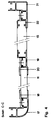
- FIGS 1 to 8 illustrate the present invention by way of example.
- FIG. 1 shows the perspective view of a box structure according to the invention.
- the equipment room (1) In the front part, facing the cab, there is an equipment room (1), while in the rear part of the box body there is a crew room (2).
- the equipment room (1) has an inner aisle (3) arranged centrally in the longitudinal direction, and a passage (4) between the inner aisle (3) and the team room (2).
- the team room can be entered through a door (5).
- Windows (6) are provided as examples on the side walls of the box body in the area of the team room. Other arrangements of doors and windows, such as Side doors and windows on the front wall are also possible.
- the devices or goods can, for example, be brought into and taken out of the device room via the inner aisle (3).
- Storage spaces (7) which can be closed by a flap (8), are also indicated by way of example below the accessible floor.
- the size of the storage space is only indicated as an example and other subdivisions and other arrangements can also be provided, depending on the available space.
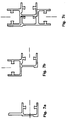
- FIG. 2 shows a section along the line AA in the box structure according to FIG. 1.
- a continuous upper flange profile (9) is connected to a side wall (11) by means of an adapter profile (10).
- Another adapter profile (12) creates a coherent connection to the continuous bottom flange profile.
- the upper chord profiles (9) and lower chord profiles (13), as well as the adapter profiles (10, 12), can be made of different materials, such as steel, brass, aluminum, aluminum alloys or plastic. Because of the easy processability of the low specific weight, the formability eg by extrusion, the strength and Low corrosion is preferred for aluminum and its alloys as a material.
- the side wall elements can represent, for example, flat materials, such as sheets, panels or structural components.
- the side wall elements are e.g. made of wood, from composites containing wood, plastics, fibers, fabric and / or metals or the side walls are structural components made of composite materials containing plastics, fibers, fabric and / or metals.
- Composites containing aluminum sheet as the outer layer are preferred; any intermediate layer can e.g. of plastics, optionally in the form of foams, or metals in the form of e.g. Expanded metals or honeycombs exist, and the inner layer can also contain plastics or metals, in particular aluminum in sheet or plate form.
- the side wall elements can also e.g. be flat aluminum profiles. Furthermore, the side wall elements can be designed to be insulating against heat and cold and / or sound.
- FIG. 3 shows a section along the line B-B in the box structure according to FIG. 1.
- the continuous top flange profile (9) is connected to the elements of a frame (15) by means of the adapter profile (14).
- the frame (15) is based on the continuous lower flange profile (13) and is fastened to the lower flange profile with the adapter profile (16).
- FIG. 4 shows a section along the line C-C in the box structure according to FIG. 1.
- the box structure has the post profiles (17 and 21) on the corner edges.
- the post profiles have the same cross section as the roof belt profiles. This has advantages in manufacturing, warehousing and processing the construction elements for the box body.
- the side wall (11) Connected to the post profile (17), held by an adapter profile (18), is the side wall (11).
- the side wall (11) extends over the crew compartment of the box body.
- a supplementary profile (19) is arranged between the side wall part of the team room and the side wall part of the equipment room, which creates the transition between the structural elements of the side wall and the frame (15).
- the side wall (11) is fixed to the supplementary profile (19) by means of an adapter profile (20).
- the frame (15) which in turn is composed of profile pieces, is arranged between the supplementary profile (19) and the post profile (21) and is fixed by the adapter profile (22). Covers, in particular movable covers, as mentioned above, can be attached between the post profiles, the profile pieces and the lower and upper flange profiles in the area of the equipment compartment.
- 5a to 5c show examples of possible cross sections of shapes of an adapter profile (5a), an upper chord profile (5b) and in FIG. 5c the cross section through the upper chord profile according to FIG. 5b applied to the adapter profile according to FIG. 5a.
- Fig. 6 shows the section through an example of a supplementary profile (19) or supplementary post.
- the side wall (11) can be placed on the supplementary profile (19)
- the structural elements of the frame (15) can be arranged.
- the supplementary profile thus creates the connection between the side wall elements between the team room and the equipment room in the box body.
- FIG. 7 shows a lower chord profile variant, an adapter profile being shown in 7a, a lower chord profile in 7b and the joined elements from FIGS. 7a and 7b in 7c.
- FIG. 8 an exemplary embodiment of a lower chord profile is shown in section with 8a.
- Fig. 8c, 8d and 8e are the profile cross sections of various adapter profiles, respectively. Lower chord profiles shown.
- An adapter profile according to FIG. 8c is used, for example, in the area of the transition from a wall structure to the framework structure.
- a profile according to Fig. 8d exemplifies an embodiment for less stressed areas of a lower flange profile, e.g. can be assembled with cross members and a sheet metal floor to form a floor structure.
- a profile according to Fig. 8e exemplifies an embodiment for heavily loaded areas of a lower flange profile.
- the lower flange profile can e.g. can be assembled with a wooden floor, a sheet metal floor, a sheet metal profile or a floor made of composite materials and cross members to form a particularly stable floor construction.
- connection area of the profile according to FIG. 8e which extends over two grooves, makes it possible, for example, to connect elements such as floors or cross members of greater material thickness.
- 8f relates to the exemplary cross section of a post profile or top flange profile.
- EP-A-0 136 264 relates in particular to a frame for a box structure e.g. for road vehicles with profile bars or the like connected to one another via corner connecting pieces, which have longitudinal grooves with undercuts, if appropriate provided on both sides of their cross section, into which a clamping piece is inserted.
- EP-B-0 185 678 relates to body structures for road vehicles in lightweight construction from a roof, a floor and side wall elements, the latter being connected to the roof by means of upper flange profiles and to the floor by means of lower flange profiles.
- the upper chord profile and the lower chord profile are each provided with at least one molded-on flag which abuts the outer surface of the side wall element, the roof and / or the floor, the flag / s and outer surface being connected by means of an adhesive, and by at least one each on the upper and Bottom flange profile bolted profile piece are complemented to form a U-shaped channel receiving an end face of the side wall element, the roof or the floor.
- the box structures have no welded connections. This makes it possible, for example, to paint the individual components before assembly. After assembling the profile structure and the wall elements, so-called finishing work is generally no longer necessary.
- windows and doors can be installed individually in terms of dimensions and installation position.
- the team room is located at the rear end of the box body.
- the remaining space in the box structure at the front end is intended as an equipment room.
- the arrangement of the team room at the rear end of the box body and the arrangement of at least one door on the rear wall are inventive. This makes it possible to leave the team room through the rear door if, for example, side doors cannot be opened due to side disabilities.
- An advantageous embodiment of the present invention is to provide a usable roof surface on the roof of the box structure.
- a usable roof area is provided by a roof section with increased load capacity and e.g. created with brackets, such as struts, railings, eyelets and / or hooks for fastening the roof loads.
- the usable roof area can extend over the entire length and / or the entire width of the box structure.
- the present invention also relates to the use of the box body for simultaneous transportation of people and equipment in the emergency medical service.
- the box bodies can be mounted on road and rail vehicles. Street vehicles and in particular trucks are preferred.
- the use of the box bodies in the emergency services is preferred for use by the fire brigade, water protection or environmental protection services and in these services, in particular on first-aid vehicles.
Landscapes
- Engineering & Computer Science (AREA)
- Chemical & Material Sciences (AREA)
- Combustion & Propulsion (AREA)
- Transportation (AREA)
- Mechanical Engineering (AREA)
- Body Structure For Vehicles (AREA)
Claims (12)
- Véhicule, et en particulier camion, qui présente une cabine de conducteur et une superstructure en caisse indépendante de la cabine de conducteur, la superstructure en caisse présentant au moins un espace pour recevoir des personnes et des moyens destinés au transport des personnes et au moins un espace pour recevoir des appareils et/ou des marchandises et des moyens destinés au transport des appareils, caractérisé en ce que l'espace (2) pour recevoir les personnes et les moyens destinés au transport des personnes sont agencés à l'extrémité arrière de la superstructure en caisse et en ce qu'il est prévu à l'extrémité arrière de la superstructure en caisse au moins une porte dans la paroi arrière.
- Véhicule selon la revendication 1, caractérisé en ce que la superstructure en caisse présente une liaison intérieure accessible entre l'espace (2) pour recevoir les personnes et l'espace (1) pour recevoir le matériel et/ou les marchandises.
- Véhicule selon la revendication 1, caractérisé en ce que l'espace (1) pour recevoir le matériel présente un couloir intérieur accessible (3) à l'intérieur de la superstructure en caisse.
- Véhicule selon l'une ou l'autre des revendications 2 et 3, caractérisé en ce que la liaison intérieure accessible (4) et le couloir intérieur accessible (3) sont en liaison mutuelle.
- Véhicule selon la revendication 1, caractérisé en ce que la superstructure en caisse présente des profilés de membrure supérieure (9) et des profilés de membrure inférieure (13) qui s'étendent sur toute sa longueur et sur toute sa largeur.
- Véhicule selon la revendication 5, caractérisé en ce que les profilés de membrure supérieure (9) présentent en continu la même section transversale profilée et en ce que les profilés de membrure inférieure (13) présentent en continu la même section transversale profilée.
- Véhicule selon la revendication 1, caractérisé en ce que la superstructure en caisse présente des profilés de membrure supérieure (9), des profilés de membrure inférieure (13) et des profilés de coin, les profilés de coin présentant la même section transversale profilée que les profilés de membrure supérieure et/ou les profilés de membrure inférieure.
- Véhicule selon la revendication 1, caractérisé en ce que la superstructure en caisse présente des profilés de membrure supérieure (9) et des profilés de membrure inférieure (13) d'une section transversale profilée égale en continu, et une ossature (15) dans la région de l'espace pour loger le matériel entre le profilé de membrure supérieure et inférieure, et en ce qu'il est prévu une structure de paroi (11) dans la région de l'espace pour recevoir les personnes, et un système adaptateur (9, 10 ; 12, 13 ; 17, 18 ; 19, 20) qui réalise la liaison entre l'ossature et la structure de paroi.
- Véhicule selon la revendication 8, caractérisé en ce que le système adaptateur (9, 10 ; 12, 13 ; 17, 18 ; 19, 20) comporte des profilés qui présentent une section transversale en forme de L dans la configuration de profilés pour loger une structure de paroi (11), et en ce que les profilés (14, 16, 19, 22) présentent une section transversale en forme de U dans la configuration de profilés pour loger une ossature (15), un porte-à-faux étant prévu respectivement à l'intérieur sur chacun des deux bras du profilé en U.
- Véhicule selon la revendication 9, caractérisé en ce que les structures de paroi (11) sont reçues par la partie profilée (9, 13, 17, 19) présentant la section transversale en forme de L, et en qu'elles sont fixées de manière à tenir par un profilé adaptateur (10, 12, 18, 20) qui est appliqué de telle manière contre la partie profilée qu'il en résulte une partie profilée d'une section transversale en forme de U.
- Application de la superstructure en caisse selon la revendication 1, pour le transport simultané de personnes et de matériel pour les services de secours.
- Application de la superstructure en caisse selon la revendication 1, pour les véhicules des sapeurs pompiers.
Applications Claiming Priority (2)
| Application Number | Priority Date | Filing Date | Title |
|---|---|---|---|
| CH3238/91 | 1991-11-06 | ||
| CH3238/91A CH685196A5 (de) | 1991-11-06 | 1991-11-06 | Kastenaufbau für Fahrzeuge. |
Publications (2)
| Publication Number | Publication Date |
|---|---|
| EP0541485A1 EP0541485A1 (fr) | 1993-05-12 |
| EP0541485B1 true EP0541485B1 (fr) | 1996-12-27 |
Family
ID=4251646
Family Applications (1)
| Application Number | Title | Priority Date | Filing Date |
|---|---|---|---|
| EP92810819A Expired - Lifetime EP0541485B1 (fr) | 1991-11-06 | 1992-10-23 | Véhicule |
Country Status (5)
| Country | Link |
|---|---|
| EP (1) | EP0541485B1 (fr) |
| CH (1) | CH685196A5 (fr) |
| CZ (1) | CZ331492A3 (fr) |
| DE (1) | DE59207765D1 (fr) |
| HU (1) | HUT67719A (fr) |
Families Citing this family (21)
| Publication number | Priority date | Publication date | Assignee | Title |
|---|---|---|---|---|
| DE4326840A1 (de) * | 1993-08-10 | 1995-02-16 | Niesmann & Bischoff Gmbh | Ringankersystem |
| FR2710306B1 (fr) * | 1993-09-23 | 1998-01-23 | Sides | Perfectionnement aux carrosseries en alliage d'aluminium pour véhicules utilitaires. |
| AT406573B (de) * | 1994-04-13 | 2000-06-26 | Rosenbauer Int Ag | Selbsttragender kastenaufbau für einsatzfahrzeuge, insbesondere feuerwehrfahrzeuge |
| EP0685381A1 (fr) * | 1994-05-31 | 1995-12-06 | Alusuisse-Lonza Services AG | Cabine pour véhicules et équipement |
| DE29500741U1 (de) * | 1995-01-18 | 1995-03-02 | Bannas Peter | Verbindungsschiene aus Metall für Aufbauten von Nutzfahrzeugen |
| FR2737550B1 (fr) * | 1995-08-04 | 1997-10-24 | Asca Carrossier Constructeur | Brancard superieur pour carrosseries de vehicules |
| DE19546458A1 (de) * | 1995-12-13 | 1997-06-19 | Metz Feuerwehrgeraete Gmbh | Einsatzfahrzeug |
| NL1002931C1 (nl) * | 1996-01-15 | 1996-06-03 | Vereniging Verenigde Carrosser | Carrosseriesamenstel. |
| EP0930222A3 (fr) * | 1998-01-15 | 2002-04-10 | Bafi, Balmer U. | Elément d' assemblage de panneaux légers |
| EP1090830B1 (fr) * | 1999-10-05 | 2004-09-08 | Alcan Technology & Management AG | Connection de structures assemblées |
| DE20217818U1 (de) * | 2002-11-18 | 2004-04-08 | Binz Gmbh & Co | Einsatzfahrzeug, insbesondere Sturmfahrzeug zum Erstürmen von Objekten |
| DE102004015252A1 (de) * | 2004-03-29 | 2005-10-20 | Spier Gmbh & Co Fahrzeug Kg | Bodenrahmen-Profilschiene für ein Fahrzeug |
| FR2873636B1 (fr) * | 2004-07-30 | 2007-12-28 | Sambuling Soc Par Actions Simp | Cellule de vehicule automobile, destinee a un amenagement fonctionnel |
| WO2007012710A1 (fr) * | 2005-07-25 | 2007-02-01 | Sambuling | Cellule de vehicule automobile, destinee a un amenagement fonctionnel |
| GB2458956A (en) * | 2008-04-04 | 2009-10-07 | Gordon Murray Design Ltd | Vehicle chassis |
| ITMN20130002A1 (it) * | 2013-01-22 | 2014-07-23 | Luca Paganini | Furgonatura autoportante per autocarri. |
| EP2783953B1 (fr) | 2013-03-27 | 2018-10-31 | Iveco Magirus Ag | Profil de bord pour border une superstructure d'un véhicule de secours, en particulier d'un véhicule de pompiers |
| CN103350724B (zh) * | 2013-07-23 | 2016-04-20 | 浙江双友物流器械股份有限公司 | 一种厢式车的车厢 |
| WO2017175192A1 (fr) * | 2016-04-08 | 2017-10-12 | Prinoth S.P.A. | Dameuse à neige |
| PL422829A1 (pl) * | 2017-09-13 | 2019-03-25 | Pojazdy szynowe PESA Bydgoszcz Spółka Akcyjna | Wyłożenie ściany bocznej pojazdu |
| DE102021214650A1 (de) * | 2021-12-20 | 2023-06-22 | Siemens Mobility GmbH | Wagenkasten für ein Fahrzeug zur Personenbeförderung |
Family Cites Families (7)
| Publication number | Priority date | Publication date | Assignee | Title |
|---|---|---|---|---|
| GB462622A (en) * | 1935-11-27 | 1937-03-12 | James Parker Garner | Improvements in road vehicles |
| GB1148752A (en) * | 1965-05-05 | 1969-04-16 | Mickleover Transp Ltd | Improvements in or relating to adjustably jointed frameworks |
| US3633970A (en) * | 1969-11-20 | 1972-01-11 | James J Langhals | Welding truck containing all required equipment |
| GB2081331A (en) * | 1980-07-10 | 1982-02-17 | Carmichael Fire & Bulk Ltd | Building or Vehicle Panelling Structure |
| WO1985005337A1 (fr) * | 1984-05-21 | 1985-12-05 | Schweizerische Aluminium Ag | Caisse de vehicule |
| DE3446734A1 (de) * | 1984-12-21 | 1986-07-03 | Iveco Magirus AG, 7900 Ulm | Kastenkonstruktion, insbesondere fuer nutzfahrzeuge wie brandschutzfahrzeuge |
| DE8914164U1 (fr) * | 1989-12-01 | 1990-02-01 | Dornier Gmbh, 7990 Friedrichshafen, De |
-
1991
- 1991-11-06 CH CH3238/91A patent/CH685196A5/de not_active IP Right Cessation
-
1992
- 1992-10-23 EP EP92810819A patent/EP0541485B1/fr not_active Expired - Lifetime
- 1992-10-23 DE DE59207765T patent/DE59207765D1/de not_active Expired - Fee Related
- 1992-10-29 HU HU9203398A patent/HUT67719A/hu unknown
- 1992-11-05 CZ CS923314A patent/CZ331492A3/cs unknown
Also Published As
| Publication number | Publication date |
|---|---|
| CH685196A5 (de) | 1995-04-28 |
| HUT67719A (en) | 1995-04-28 |
| CZ331492A3 (en) | 1993-07-14 |
| DE59207765D1 (de) | 1997-02-06 |
| EP0541485A1 (fr) | 1993-05-12 |
| HU9203398D0 (en) | 1993-03-01 |
Similar Documents
| Publication | Publication Date | Title |
|---|---|---|
| EP0541485B1 (fr) | Véhicule | |
| EP1061009B1 (fr) | Conteneur à marchandise repliable pour transport aérien | |
| EP1799603B1 (fr) | Cabine d'ascenseur modulaire | |
| EP0755285A1 (fr) | Caisse monocoque pour vehicules d'intervention, notamment fourgons de pompiers | |
| EP0465427A1 (fr) | Superstructure de caisse pour véhicules ferroviaires | |
| DE102006011611B4 (de) | Transportcontainer zur Personenbeförderung | |
| EP2520490B1 (fr) | Utilisation d'un composant léger | |
| DE102008048151A1 (de) | Vorrichtung zum Unterteilen eines Frachtraums | |
| EP0905000A1 (fr) | Plancher intermédiaire pour une voiture à deux niveaux | |
| EP2116420B1 (fr) | Structure de coffre dotée d'un panneau comprenant un dispositif de fixation | |
| DE60022604T2 (de) | System zur Befestigung von Gegenständen im Inneren eines Kraftfahrzeugs sowie gleitende Ankerelemente hierfür | |
| DE3316412A1 (de) | Kabine | |
| DE102021108665A1 (de) | Verbundprofil für einen Kofferaufbau für ein Nutzfahrzeug sowie Kofferaufbau für ein Nutzfahrzeug | |
| EP3388317B1 (fr) | Construction de véhicule frigorifique | |
| DE202012011397U1 (de) | Fahrzeugaufbau sowie Lastkraftwagen und Lastkraftwagenanhänger | |
| DE102012013605A1 (de) | Kraftwagen mit Tragrahmen und Aufbau | |
| EP1630307B1 (fr) | Toilettes mobiles | |
| DE4420632A1 (de) | Mehrzweck-Raupenfahrzeug | |
| DE4309583C2 (de) | Lifteinbau in einem mehrstöckigen Schienenfahrzeug | |
| DE2148067A1 (de) | Frachtcontainer | |
| EP0779202B1 (fr) | Véhicule d'intervention | |
| DE1945636A1 (de) | Ladegutbehaelter mit senkrecht verstellbaren Ladedecks | |
| EP0635405B1 (fr) | Auto-caravane avec dispositif de fixation de ceintures de sécurité | |
| EP0748720B1 (fr) | Grand tiroir destiné à être monté dans un véhicule de service | |
| DE602004000011T2 (de) | Nutz- oder Freizeitfahrzeug mit variablem Innenraum |
Legal Events
| Date | Code | Title | Description |
|---|---|---|---|
| PUAI | Public reference made under article 153(3) epc to a published international application that has entered the european phase |
Free format text: ORIGINAL CODE: 0009012 |
|
| AK | Designated contracting states |
Kind code of ref document: A1 Designated state(s): AT BE CH DE ES FR GB IT LI NL SE |
|
| 17P | Request for examination filed |
Effective date: 19931022 |
|
| 17Q | First examination report despatched |
Effective date: 19950630 |
|
| GRAG | Despatch of communication of intention to grant |
Free format text: ORIGINAL CODE: EPIDOS AGRA |
|
| GRAH | Despatch of communication of intention to grant a patent |
Free format text: ORIGINAL CODE: EPIDOS IGRA |
|
| RBV | Designated contracting states (corrected) |
Designated state(s): DE FR IT |
|
| GRAH | Despatch of communication of intention to grant a patent |
Free format text: ORIGINAL CODE: EPIDOS IGRA |
|
| ITF | It: translation for a ep patent filed |
Owner name: DE DOMINICIS & MAYER S.R.L. |
|
| RAP1 | Party data changed (applicant data changed or rights of an application transferred) |
Owner name: ALUSUISSE TECHNOLOGY & MANAGEMENT AG |
|
| GRAA | (expected) grant |
Free format text: ORIGINAL CODE: 0009210 |
|
| AK | Designated contracting states |
Kind code of ref document: B1 Designated state(s): DE FR IT |
|
| REF | Corresponds to: |
Ref document number: 59207765 Country of ref document: DE Date of ref document: 19970206 |
|
| ET | Fr: translation filed | ||
| PLBE | No opposition filed within time limit |
Free format text: ORIGINAL CODE: 0009261 |
|
| STAA | Information on the status of an ep patent application or granted ep patent |
Free format text: STATUS: NO OPPOSITION FILED WITHIN TIME LIMIT |
|
| 26N | No opposition filed | ||
| PGFP | Annual fee paid to national office [announced via postgrant information from national office to epo] |
Ref country code: FR Payment date: 20021017 Year of fee payment: 11 |
|
| PGFP | Annual fee paid to national office [announced via postgrant information from national office to epo] |
Ref country code: DE Payment date: 20021029 Year of fee payment: 11 |
|
| PG25 | Lapsed in a contracting state [announced via postgrant information from national office to epo] |
Ref country code: DE Free format text: LAPSE BECAUSE OF NON-PAYMENT OF DUE FEES Effective date: 20040501 |
|
| PG25 | Lapsed in a contracting state [announced via postgrant information from national office to epo] |
Ref country code: FR Free format text: LAPSE BECAUSE OF NON-PAYMENT OF DUE FEES Effective date: 20040630 |
|
| REG | Reference to a national code |
Ref country code: FR Ref legal event code: ST |
|
| PG25 | Lapsed in a contracting state [announced via postgrant information from national office to epo] |
Ref country code: IT Free format text: LAPSE BECAUSE OF NON-PAYMENT OF DUE FEES;WARNING: LAPSES OF ITALIAN PATENTS WITH EFFECTIVE DATE BEFORE 2007 MAY HAVE OCCURRED AT ANY TIME BEFORE 2007. THE CORRECT EFFECTIVE DATE MAY BE DIFFERENT FROM THE ONE RECORDED. Effective date: 20051023 |