EP0538526B1 - Vorrichtung zum Richten einer Kante eines rechteckigen Stück-Tuch - Google Patents
Vorrichtung zum Richten einer Kante eines rechteckigen Stück-Tuch Download PDFInfo
- Publication number
- EP0538526B1 EP0538526B1 EP91309895A EP91309895A EP0538526B1 EP 0538526 B1 EP0538526 B1 EP 0538526B1 EP 91309895 A EP91309895 A EP 91309895A EP 91309895 A EP91309895 A EP 91309895A EP 0538526 B1 EP0538526 B1 EP 0538526B1
- Authority
- EP
- European Patent Office
- Prior art keywords
- line
- plate
- flexible sheet
- edge
- movable
- Prior art date
- Legal status (The legal status is an assumption and is not a legal conclusion. Google has not performed a legal analysis and makes no representation as to the accuracy of the status listed.)
- Expired - Lifetime
Links
- 238000010276 construction Methods 0.000 description 4
- 238000006073 displacement reaction Methods 0.000 description 2
Images




Classifications
-
- D—TEXTILES; PAPER
- D06—TREATMENT OF TEXTILES OR THE LIKE; LAUNDERING; FLEXIBLE MATERIALS NOT OTHERWISE PROVIDED FOR
- D06F—LAUNDERING, DRYING, IRONING, PRESSING OR FOLDING TEXTILE ARTICLES
- D06F67/00—Details of ironing machines provided for in groups D06F61/00, D06F63/00, or D06F65/00
- D06F67/04—Arrangements for feeding or spreading the linen
Definitions
- This invention relates to a device for straightening one side edge of the four side edges of a rectangular flexible sheet.
- Laundry shops generally use automatic machines for pressing and folding relatively large rectangular flexible sheets such as bed sheets, quilt covers and bed covers, which have been washed and dried. Since such a rectangular sheet to be processed by the press machine is generally in a crumpled state, it is necessary to straighten one of the four edges thereof before the sheet is fed to the machine. Because of the large size of the sheet, it is difficult for a worker to perform the straightening operation by himself.
- a device for aligning an edge of a flexible sheet with a conveyor which is to transport the sheet is shown in FR-A-2 307 907.
- the present invention has been made to provide a new device which can straighten one of the four side edges of a rectangular flexible sheet as mentioned above.
- a device for processing a rectangular flexible sheet having four corners A - D to straighten one edge DA of the four edges AB, BC, CD and DA thereof comprising:
- the present invention provides a device for processing a rectangular flexible sheet having four corners A - D to straighten one edge DA of the four edges AB, BC, CD and DA thereof, comprising:
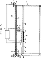
- the present invention provides a device for processing a rectangular flexible sheet, generally designated as Y in Fig. 7 and having four corners A - D, to straighten one edge DA of the four edges AB, BC, CD and DA thereof.
- a frame to which an elongated plate 4 is secured.
- the plate 4 is composed of a front section 41 and a rear section 43.
- the front section 41 has a tapered front tip end 42.
- the rear section 43 has first and second locations L 1 and L 2 spaced apart from each other with a distance greater than any of the edges of the sheet Y.
- the frame 1 has a guide rail 11 extending above the plate 4 and in parallel with the longitudinal direction of the plate 4.
- a movable member 2 which has a top plate 20 and a pair of side plates 21 extending downwardly from the both sides of the top plate 20.
- a pair of spaced apart, right and left holders 22 and 23 are secured to the side plates 21.
- Each of the holders 22 and 23 is adapted to hold a portion of the flexible sheet Y.
- the right holder 22 holds the corner portion (vertex) A of the sheet Y while the left holder 23 holds an intermediate portion P of the edge AB (see Fig. 7).
- the holders 22 and 23 may be of any structure as long as they can firmly hold the sheet Y.
- An air chuck type holder adapted to be opened and closed by compressed air for releasing and clipping the sheet Y may be suitably used.
- the distance between the right and left holders 22 and 23 be about 40-60 cm.
- Displacing means 3 is provided to displace the movable member 2 along the guide rail 11.
- a pair of sprocket wheels 32 are mounted on the opposite ends of the guide rail 11.
- the wheel 32 provided in the rear end of the rail 11 is operatively connected to a drive motor 31.
- a chain 33 is provided between the two wheels 32 for meshing therewith. Both ends of the chain 33 are fixed to the movable member 2 so that the movable member 2 is displaced forward and backward upon the driving of the motor 31 in either direction.
- any other suitable mechanism may be adopted for the displacing means 3.
- the holders 22 and 23 are moved therewith.
- the right and left holders 22 and 23 are moved along spaced apart, first and second lines R 1 and R 2 which position between the side edges of the plate 4 and between which the tapered tip end 42 is located.
- the sheet Y held by the two holders 22 and 23 is pulled and displaced on the plate 4 by the movement of the movable member with the vertex A thereof being moved along the first line R 1 of the movement of the right holder 22.
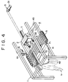
- the tapered end of the fore section 41 of the plate serves to laterally spread the sheet Y.
- Conveyer means 5 is disposed adjacent to the fore section 41 of the plate 4.
- the conveyer means 5 in the illustrated embodiment includes four spaced apart endless belts 52 laterally extending between a pair of rollers 51 provided on both sides of the plate 4.
- the belts 52 are wound around the plate 4 to form on the plate 4 a conveying surface which crosses the first and second lines R 1 and R 2 along which the right and left holders 22 and 23 travel, respectively, as shown in Fig. 2.
- Drive means 6 is connected to one of the rollers 51 (left roller in the illustrated embodiment) to drive the left roller.
- the drive means 6 includes a sprocket and chain mechanism and a motor 61 to drive the sprocket.
- the endless conveyer belts 52 are moved leftward or rightward upon revolution of the motor 61 in either direction.
- the sheet Y brought into supporting engagement with the belt conveyer 5 is moved in the lateral direction of the plate 4.
- Detector means 71 is provided for determining whether or not the flexible sheet Y on the conveying surface is present on the first line R 1 .
- the detector means 71 in the illustrated embodiment is a photoelectric tube disposed in the gap of the conveyer belts 52 just beneath the first line R 1 .
- the detector 71 detects the presence of the sheet Y.
- the detector 71 detects the absence of the sheet Y.
- the detector means 71 and the drive means 6 are electrically coupled to control means 10.
- the control means 10 instructs the drive means 6 to operate so that the conveying surface (i.e. the conveyer belts 52 above the plate 4) runs leftward.
- the control means 10 instructs the drive means 6 to operate so that the conveyer belts 52 run rightward.
- Designated as 72 is sensor means for detecting the passage of the edge CD of the flexible sheet Y through the predetermined first location L 1 of the plate 4 so as to determine the completion of the displacement of the entire sheet Y on the plate 4.
- the sensor means 72 may be a photoelectric tube disposed near the center axis of the plate 4.
- the sensor means 72 and the displacing means 3 are also coupled to the control means 10 so that when the sensor means 72 detects the passage of the edge CD, the displacing means 3 stops operation to stop the movement of the movable means 2, namely to stop the longitudinal movement of the flexible sheet Y. Construction of the control means 10 is well known in the art and the explanation thereof is omitted here.
- the above described device operates as follows. First, the control means 10 is operated to position the movable means 2 in the home position as shown in Fig. 1. An operator picks up desired one corner A of the four corners A, B, C and D of the flexible sheet Y with his right hand and then a desired portion P of the edge AB adjacent to the corner A with his left hand. The sheet Y is then manually attached to the device as shown in Fig. 1 to start the straightening of the edge DA. Namely, the corner A is held by the right holder 22 while the portion P of the edge AB is held by the left holder 23 with the edge AP being desirably slightly strained. Since the distance between the right and left holders 22 and 23 is nearly equal to the breadth of operator's shoulders, the attaching operation can be easily performed.
- the movable means 2 is gradually displaced toward the rear end of the plate 4.
- the trailed portion of the sheet Y is engaged by the tapered end 42 of the plate 4 and is pulled so that the portion of the sheet Y adjacent to the edge DA is laterally and longitudinally spread as the movable means 2 is displaced (Fig. 4).
- the conveyer means 5 is operated to displace the supported sheet Y leftward.
- the conveyer means 5 shifts the supported sheet Y rightward.
- the trailing edge DA is aligned on the first line R 1 along which the right holder 22 holding the corner A travels.
- the movable means 2 After the movable means 2 has displaced so that the edge CD has passed above the sensor means 72 as shown in Fig. 5, the movable means is stopped at the second location L 2 . Then, the holders 22 and 23 are opened to release the sheet Y. The sheet Y whose edge DA has been straightened is then fed to a next step such as a press machine. The movable means 2 is subsequently returned to the home position for the mounting of a new sheet.
- the sheet Y is processed for straightening the edge DA. It will be understood, however, when, in Fig. 7, a portion Q on the edge DA is attached to the left holder 23 in place of the portion P on the edge AB, then the edge AB is automatically straightened by the straightening device of the present invention.
- FIG. 6 Another preferred embodiment of the straightening device of the present invention is shown in Fig. 6 in which the same reference numerals as those in Fig. 1 designate similar component parts. Explanation of the similar parts is not repeated here.
- the second embodiment differs from the above-described first embodiment in that an edge alignment means 50 composed of a plurality (five in the specific embodiment shown) of juxtaposed conveyer means 5a through 5e is used in the second embodiment.
- Each of the conveyer means 5a through 5e has a conveying surface disposed above a plate 4 so that the total length of the conveying surfaces in the longitudinal direction of the plate 4 is greater than any of the four edges of the sheet Y.
- the conveying surfaces are adapted to run independently from each other in the lateral direction of the plate 4.
- a plurality of drive means 6a through 6e, corresponding in number to the conveyer means 5a through 5e, are provided for direction of the plate 4.
- a plurality of detector means 71a through 71e corresponding in number to the plurality of conveyer means 5a through 5e are provided for determining whether or not the flexible sheet Y on the corresponding conveying surface is present on a predetermined reference line positioned on the right side of and in parallel with the locus (first line R 1 in Fig. 2) of the movement of the right holder 22.
- the detector means 71a through 71e may be photoelectric tubes arranged in a row adjacent to the right side end of the conveying surfaces of the conveyer means 5a through 5e.
- the detector means 71a through 71e and the drive means 6a and 6e are coupled to a control means 10.
- the control means 10 instructs respective drive means 5a through 5e to operate so that each of the conveying surfaces runs leftward when the corresponding detector means detects the presence of the flexible sheet Y on the reference line or rightward when the corresponding detector means does not detect the presence of the flexible sheet Y on the reference line.
- control means 10 in this second embodiment is so arranged that the drive means 6a through 6e are made operable only after the flexible sheet Y has been placed on the conveying surfaces of the conveyer means 5a through 5e throughout the length of the edge DA. This is achieved by utilization of the sensor means 72.
- conveyer means 5a through 5e start operation so that the the edge DA thereof is laterally displaced by the conveyer means 5a through 5e and made alignment with the reference line.
- Fig. 6 designated as 12 is an elastic pipe to supply compressed air to the holders 22 and 23 of an air chuck type construction for the actuation thereof.
- Designated as 81 is laterally extending movable bar whose both ends are slidably received by the frame 1.
- Drive means including a motor 84 and a sprocket and chain mechanism is provided for vertically moving the bar 81 between a lower position and an upper position.
- the bar 81 has a pair of spaced apart holders 82 and 83 having a construction similar to the holders 22 and 23 and each adapted to hold a portion of the sheet Y.
- the device shown in Fig. 6 operates as follows.
- An operator first attach a desired corner A of the sheet Y and an intermediate portion P of the edge AB to the holders 82 and 83, respectively, when the bar 81 is in the lower position. Then the operator starts the motor 84 to hoist up the sheet Y. The bar 81 stops moving at the upper position. The operator transfers the sheet Y from the holders 82 and 83 to the holders 22 and 23 of the movable means 2.
- the above sheet hoist up mechanism is optional and may be omitted.
- the movable means 2 is gradually displaced toward the rear end of the plate 4 in the same manner as described in connection with the first embodiment of Fig. 1.
- the trailed portion of the sheet Y is engaged by the tapered end 42 of the plate 4 and is pulled so that the portion of the sheet Y adjacent to the edge DA is laterally and longitudinally spread as the movable means 2 is displaced.
- the movable means 2 After the movable means 2 has been displaced so that the edge CD has passed above the sensor means 72, namely after the entire sheet Y has been displaced to a predetermined location on the plate 4, the movable means 2 is stopped. Then, the holders 22 and 23 are opened to release the sheet Y.
- the conveyer means 5a through 5e start operation to straighten the edge DA.
- the conveyer means 5a through 5e are operated to displace the supported sheet Y leftward.
- the conveyer means 5a through 5e shift the supported sheet Y rightward.
- the edge DA is aligned on the reference line beneath the row of the detectors 71a through 71e.
Landscapes
- Engineering & Computer Science (AREA)
- Textile Engineering (AREA)
- Registering Or Overturning Sheets (AREA)
Claims (4)
- Vorrichtung zur Behandlung eines rechteckigen nachgiebigen textilen Flächengebildes (Y) mit vier Ecken A-D mit dem Ziel, eine der Stoffkanten DA der vier Stoffkanten AB, BC, CD und DA in einer Ebene auszurichten, zu der gehören:ein Rahmen (1)eine Platte (4), die am Rahmen befestigt ist und sich in Längsrichtung vom vorderen Teil (41) zum hinteren Teil (43) erstreckt, wobei die Platte (4) eine erste Bezugsstelle (L1) in der Nähe des vorderen Teils und eine zweite Bezugsstelle (L2) in der Nähe des hinteren Teils aufweist, die erste und zweite Bezugsstelle in Längsrichtung in einem Abstand voneinander angeordnet sind, der größer als jede der Kanten des nachgiebigen textilen Flächengebildes ist, und wobei der vordere Teil (41) kegelförmig ausgeführt ist, so daß er eine kegelförmige Spitze (42) bildet;eine verfahrbare Vorrichtung (2), die sich auf dem Rahmen (1) abstützt und oberhalb der Platte (4) in Längsrichtung der Platte beweglich ist;ein Paar in Querrichtung voneinander in einem bestimmten Abstand angeordnete erste und zweite Spannvorrichtungen (22, 23) zum Einspannen der Ecke A und eines mittleren Bereichs P auf der Kante AB des nachgiebigen textilen Flächengebildes, wobei die erste und die zweite Spannvorrichtung (22, 23) an der verfahrbaren Vorrichtung (2) für die Verschiebung zusammen mit dieser befestigt sind, so daß sich die erste und die zweite Spannvorrichtung (22, 23), wenn die verfahrbare Vorrichtung (2) verschoben wird, auf bestimmten in einem gewissen Abstand angeordneten Linien. der ersten und zweiten Linie (R1 und R2), bewegen, wobei die kegelförmige Spitze (42) der Platte zwischen der ersten und der zweiten Linie angeordnet ist;eine Verschiebevorrichtung (3) zum Bewegen der verfahrbaren Vorrichtung (2);eine Fördereinrichtung (5), die eine sich in Querrichtung zwischen der einen Außenseite und der anderen Außenseite erstreckende Transportfläche aufweist, so daß die erste Linie (R1) zwischen der einen und der anderen Außenseite und die zweite Linie (R2) zwischen der ersten Linie und der anderen Außenseite angeordnet ist, wobei sich die Transportfläche oberhalb der Platte (4) befindet und so ausgelegt ist, daß sie sich in Querrichtung zur Platte bewegt;eine Antriebsvorrichtung (6) zum Antrieb der Fördereinrichtung (5);eine Kontrolleinrichtung (71) zur Prüfung, ob sich das nachgiebige Flächengebilde (4) auf der Fördereinrichtung (5) der ersten Linie (R1) befindet; undeine Steuereinrichtung (10), die mit der Kontrolleinrichtung (71) und der Antriebsvorrichtung (6) verbunden ist und zur Steuerung des Betriebs der Antriebsvorrichtung (6) bestimmt ist, so daß sich die Transportfläche in Richtung von der ersten Linie (R1) zur zweiten Linie (R2) bewegt, wenn die Kontrolleinrichtung (71) feststellt, daß das nachgiebige textile Flächengebilde (Y) an der ersten Linie (R1) vorhanden ist, und sich in Richtung von der zweiten Linie (R2) zur ersten Linie (R1) bewegt, wenn die Kontrolleinrichtung (71) nicht feststellen kann, daß sich das nachgiebige textile Flächengebilde (Y) auf der ersten Linie (R1) befindet, so daß die Ecke A des nachgiebigen textilen Flächengebildes, die von der ersten Spannvorrichtung (21) gehalten wird, und der mittlere Bereich P auf der Kante AB, der von der zweiten Spannvorrichtung (23) gehalten wird, auf der Platte (4) durch Bewegen der Verschiebevorrichtung (3) über die erste Bezugsstelle (L1) zur zweiten Bezugsstelle (L2) transportiert wird, wobei die Kante DA des nachgiebigen textilen Flächengebildes (Y) mit Hilfe der Fördereinrichtung (5) in Querrichtung bewegt und parallel zur ersten Linie (R1) ausgerichtet wird.
- Vorrichtung nach Anspruch 1, zu der des weiteren gehören: eine Gebereinrichtung (72) zur Registrierung, ob die Kante CD des nachgiebigen textilen Flächengebildes über die erste Bezugsstelle (L1) geführt wird, wobei die Gebereinrichtung mit der Steuereinrichtung (10) verbunden ist, so daß die Verschiebevorrichtung (3), wenn die Gebereinrichtung registriert, daß sich die Kante CD über sie hinweg bewegt, anhält und die verfahrbare Vorrichtung (2) ebenfalls anhält.
- Vorrichtung zur Behandlung eines rechteckigen nachgiebigen textilen Flächengebildes (Y) mit vier Ecken A-D mit dem Ziel, eine der Stoffkanten DA der vier Stoffkanten AB, BC, CD und DA in einer Ebene auszurichten, zu der gehören:ein Rahmen (1),eine Platte (4), die am Rahmen befestigt ist und sich in Längsrichtung vom vorderen Teil (41) zum hinteren Teil (43) erstreckt, wobei die Platte (4) eine erste Bezugsstelle (L1) in der Nähe des vorderen Teils und eine zweite Bezugsstelle (L2) in der Nähe des hinteren Teils aufweist, die erste und zweite Bezugsstelle in Längsrichtung in einem Abstand voneinander angeordnet sind, der größer als jede der Kanten des nachgiebigen textilen Flächengebildes ist, und wobei der vordere Teil (41) kegelförmig ausgeführt ist, so daß sie eine kegelförmige Spitze (42) bildet;eine verfahrbare Vorrichtung (2), die sich auf dem Rahmen (1) abstützt und auf der Platte (4) in Längsrichtung der Platte beweglich ist;ein Paar in Querrichtung, voneinander in einem bestimmten Abstand angeordnete erste und zweite Spannvorrichtungen (22, 23) zum Einspannen der Ecke A und eines mittleren Bereichs P auf der Kante AB des nachgiebigen textilen Flächengebildes, wobei die erste und die zweite Spannvorrichtung (22, 23) an der verfahrbaren Vorrichtung (2) für die Verschiebung zusammen mit dieser befestigt sind, so daß sich die erste und die zweite Spannvorrichtung (22, 23), wenn die verfahrbare Vorrichtung (2) verschoben wird, auf bestimmten in einem gewissen Abstand angeordneten Linien, der ersten und zweiten Linie (R1 und R1), bewegen, wobei die kegelförmige Spitze (42) der Platte (4) zwischen der ersten und der zweiten Linie angeordnet ist;eine Verschiebevorrichtung (3) zum Bewegen der verfahrbaren Vorrichtung (2);eine Anzahl von nebeneinander angeordneten Fördereinrichtungen (5a-5e), die jeweils eine sich in Querrichtung zwischen der einen Außenseite und der anderen Außenseite erstreckende Transportfläche aufweisen, so daß die erste Linie (R1) zwischen der einen und der anderen Außenseite und die zweite Linie (R2) zwischen der ersten Linie und der anderen Außenseite angeordnet ist, wobei sich die Transportflächen oberhalb der Platte (4) befinden und so gestaltet sind, daß die Gesamtlänge der Transport flächen in Längsrichtung der Platte größer ist als der Abstand zwischen der ersten und der zweiten Bezugsstelle der Platte ist, wobei die Transportflächen so ausgelegt sind, daß sie sich unabhängig voneinander in Querrichtung der Platte bewegen und eine Bezugslinie zwischen der ersten Linie (R1) und der einen Außenseite aufweisen;eine der Anzahl der Fördereinrichtungen (5a-5e) entsprechende Anzahl von Antriebsvorrichtungen (6a-6e) zum Antrieb der entsprechenden Transportflächen in Querrichtung der Platte (4);eine der Anzahl der Fördereinrichtungen entsprechende Anzahl von Kontrolleinrichtungen (71a-71e) zur Prüfung, ob sich das nachgiebige textile Flächengebilde (Y) auf der entsprechenden Fördereinrichtung auf der Bezugslinie befindet; undeine Steuereinrichtung (10), die mit einer Anzahl Kontrolleinrichtungen (71a-71e) und einer Anzahl Antriebsvorrichtungen (6a-6e) verbunden ist und zur Steuerung des Betriebs der entsprechenden Antriebsvorrichtungen bestimmt ist, so daß sich die Transportflächen in Richtung von der ersten Linie (R1) zur zweiten Linie (R2) bewegen, wenn die entsprechende Kontrolleinrichtung feststellt, daß das nachgiebige textile Flächengebilde (Y) an der Bezugslinie vorhanden ist, und sich in Richtung von der zweiten Linie (R2) zur ersten Linie (R1) bewegt, wenn die Kontrolleinrichtung nicht feststellen kann, daß sich das nachgiebige textile Flächengebilde auf der Bezugslinie befindet, wobei das nachgiebige textile Flächengebilde mit Hilfe der Fördereinrichtung in Querrichtung bewegt wird, so daß die Kante DA parallel zur Bezugslinie ausgerichtet wird, nachdem eine Ecke A der Ecken A-D des nachgiebigen textilen Flächengebildes, die von der ersten Spannvorrichtung (22) gehalten wird, und der mittlere Bereich P auf der Kante AB, der von der zweiten Spannvorrichtung (23) gehalten wird, durch Betätigen der Verschiebevorrichtung (3) über die Transportflächen über die erste Bezugsstelle (L1) zur zweiten Bezugsstelle (L2) transportiert worden ist.
- Vorrichtung nach Anspruch 3, zu der des weiteren gehören: eine Gebereinrichtung (72) zur Registrierung, ob die Kante CD des nachgiebigen textilen Flächengebildes über die erste Bezugsstelle (L1) geführt wird, wobei die Gebereinrichtung mit der Steuereinrichtung (10) verbunden ist, so daß die Verschiebevorrichtung, wenn die Gebereinrichtung das Passieren der Kante CD registriert, anhält, damit die verfahrbare Vorrichtung (2) ebenfalls anhält und eine Anzahl von Fördereinrichtungen (5a-5e) in Bewegung versetzt wird.
Priority Applications (1)
| Application Number | Priority Date | Filing Date | Title |
|---|---|---|---|
| DE1991621717 DE69121717T2 (de) | 1991-10-25 | 1991-10-25 | Vorrichtung zum Richten einer Kante eines rechteckigen Stück-Tuch |
Applications Claiming Priority (1)
| Application Number | Priority Date | Filing Date | Title |
|---|---|---|---|
| US07/781,838 US5179795A (en) | 1991-10-24 | 1991-10-24 | Device for straightening one edge of rectangular sheet |
Publications (2)
| Publication Number | Publication Date |
|---|---|
| EP0538526A1 EP0538526A1 (de) | 1993-04-28 |
| EP0538526B1 true EP0538526B1 (de) | 1996-08-28 |
Family
ID=25124112
Family Applications (1)
| Application Number | Title | Priority Date | Filing Date |
|---|---|---|---|
| EP91309895A Expired - Lifetime EP0538526B1 (de) | 1991-10-24 | 1991-10-25 | Vorrichtung zum Richten einer Kante eines rechteckigen Stück-Tuch |
Country Status (3)
| Country | Link |
|---|---|
| US (1) | US5179795A (de) |
| EP (1) | EP0538526B1 (de) |
| DK (1) | DK0538526T3 (de) |
Families Citing this family (12)
| Publication number | Priority date | Publication date | Assignee | Title |
|---|---|---|---|---|
| US5430915A (en) * | 1992-04-20 | 1995-07-11 | Mitsubishi Jukogyo Kabushiki Kaisha | Apparatus for spreading rectangular cloth pieces |
| DE69403267T2 (de) * | 1993-04-16 | 1998-01-15 | Mitsubishi Heavy Ind Ltd | Vorrichtung zum Ausbreiten eines rechteckigen Tuchs |
| US5515627A (en) * | 1994-07-27 | 1996-05-14 | Mccabe; Stanley G. | Apparatus and method for feeding flatwork articles |
| US5967505A (en) * | 1997-03-21 | 1999-10-19 | Levi Strauss & Co. | Automatic feeder and inverter for fabric workpieces |
| JP4268747B2 (ja) * | 2000-10-10 | 2009-05-27 | 株式会社プレックス | 矩形布片の展開方法及び展開装置 |
| US6826856B1 (en) * | 2003-08-06 | 2004-12-07 | Finishtech Ltd. | Laundry article spreader apparatus and method |
| US7555857B2 (en) * | 2006-09-13 | 2009-07-07 | Mccabe Stanley G | Article of laundry spreader and stacker |
| US7836617B2 (en) * | 2007-06-04 | 2010-11-23 | Mccabe Stanley G | Linen spreader apparatus and method |
| US7827709B2 (en) * | 2007-06-04 | 2010-11-09 | Mccabe Stanley G | Linen spreader apparatus and method |
| DK176722B1 (da) * | 2007-12-17 | 2009-04-27 | Jensen Denmark As | Fremgangsmode til overf ring af et t jstykke og vaskerimaskine til ud velse af fremgangsmoden |
| JP6511256B2 (ja) * | 2014-12-08 | 2019-05-15 | 株式会社プレックス | 方形状布類展開装置 |
| EP3452654A4 (de) * | 2016-05-05 | 2020-01-01 | Foldimate Inc. | Kompakte haushaltsartikelfaltmaschine mit verbessertem antriebsmechanismus |
Family Cites Families (20)
| Publication number | Priority date | Publication date | Assignee | Title |
|---|---|---|---|---|
| DE272768C (de) * | ||||
| DE160903C (de) * | ||||
| US1912724A (en) * | 1931-11-30 | 1933-06-06 | Stokes & Smith Co | Method and apparatus for spreading fabrics |
| NL132184C (de) * | 1966-04-21 | |||
| GB1151434A (en) * | 1966-08-02 | 1969-05-07 | Weir Henry J | Laundry Article Spreading Device |
| US3604132A (en) * | 1970-05-18 | 1971-09-14 | Mc Graw Edison Co | Spreader device for flatwork |
| US3735512A (en) * | 1971-06-18 | 1973-05-29 | A Ross | Sheet feeder and spreader means |
| US3756588A (en) * | 1972-03-06 | 1973-09-04 | Jensen Machinery Inc | Centering guide |
| FR2283979A1 (fr) * | 1974-09-04 | 1976-04-02 | Bora Sa | Appareil de transfert de pieces de linge |
| DK137809B (da) * | 1974-09-04 | 1978-05-08 | Beta Sa | Apparat til udspredning af vasketøj og overførsel af dette til en transportør. |
| FR2307907A1 (fr) * | 1975-04-18 | 1976-11-12 | Jean Michel | Preparatrice engageuse pour poser a plat un article souple sur un convoyeur |
| FR2494733A1 (fr) * | 1980-11-27 | 1982-05-28 | Jean Michel | Dispositif pour l'introduction de pieces de linge, notamment dans une machine a repasser |
| US4501529A (en) * | 1981-05-19 | 1985-02-26 | Herbert Kannegiesser Gmbh & Co. | Apparatus for feeding laundry articles to an ironing machine |
| DE3223048C2 (de) * | 1982-06-19 | 1984-07-05 | Canon K.K., Tokio/Tokyo | Verfahren zum Ausrichten eines durch Walzenpaare laufenden Papierblattes sowie Vorrichtung zur Durchführung des Verfahrens und Anwendung desselben |
| US4726501A (en) * | 1985-12-12 | 1988-02-23 | Tex-Nology Systems, Inc. | Edge steerage apparatus |
| JPH0637247B2 (ja) * | 1986-12-15 | 1994-05-18 | 三菱重工業株式会社 | リネン把持状態の認識方法及び装置 |
| US4805892A (en) * | 1988-04-04 | 1989-02-21 | Eastman Kodak Company | Cross-track registration device for sheet transport system |
| DE3839045A1 (de) * | 1988-06-04 | 1989-12-07 | Kannegiesser H Gmbh Co | Verfahren und vorrichtung zum zufuehren von waeschestuecken zu einer mangel |
| US4885853A (en) * | 1989-02-23 | 1989-12-12 | Jensen Corporation | Spreader feeder apparatus |
| US5021673A (en) * | 1989-10-10 | 1991-06-04 | Unisys Corp. (Formerly Burroughs Corp.) | Web transport with anti-skew arrangement |
-
1991
- 1991-10-24 US US07/781,838 patent/US5179795A/en not_active Expired - Lifetime
- 1991-10-25 EP EP91309895A patent/EP0538526B1/de not_active Expired - Lifetime
- 1991-10-25 DK DK91309895.0T patent/DK0538526T3/da active
Also Published As
| Publication number | Publication date |
|---|---|
| EP0538526A1 (de) | 1993-04-28 |
| DK0538526T3 (da) | 1997-01-13 |
| US5179795A (en) | 1993-01-19 |
Similar Documents
| Publication | Publication Date | Title |
|---|---|---|
| DE69516894T2 (de) | Vorrichtung zum zuführen von flachmaterialstücken | |
| US5179795A (en) | Device for straightening one edge of rectangular sheet | |
| US5440810A (en) | Apparatus for feeding and spreading laundry articles | |
| US5416992A (en) | Apparatus for spreading rectangular cloth | |
| CA1046095A (en) | Stack tilter and feeding means for automatic blank handling | |
| JPS6238258B2 (de) | ||
| US5430915A (en) | Apparatus for spreading rectangular cloth pieces | |
| JPH08300618A (ja) | 金属化画像をシート要素に転写する機械における金属化ベルトの移送装置 | |
| WO1993010032A1 (en) | Apparatus for the high speed stacking of paper sheets both by accordion-like folding of a continuous band and by superimposing separate sheets | |
| JP2695739B2 (ja) | 矩形状布片の展開装置 | |
| US4736940A (en) | Apparatus for aligning an opening of a sack | |
| US5727923A (en) | Collecting device for sheets | |
| JPH07265577A (ja) | 洗濯物処理装置へ洗濯物を供給する方法及び装置 | |
| JPH0649119B2 (ja) | 方形状布類の縁出し装置 | |
| US3211301A (en) | Papermaking machine | |
| KR0142015B1 (ko) | 직사각형상 포편의 전개장치 | |
| JPS606040Y2 (ja) | 延反機用原反供給装置 | |
| US5318288A (en) | Method and apparatus for processing sheets | |
| JP3641544B2 (ja) | 搬送生地の折重ね装置 | |
| JP2534018B2 (ja) | 方形状布類の縁出し方法 | |
| SE429731B (sv) | Anordning for placering av banavsnitt pa ett platt liggande arbetsstycke, speciellt vid tillverkning av bottenforsterkta seckar o dyl | |
| JP2987478B2 (ja) | ウエブの通布装置 | |
| EP0029726B1 (de) | Vorrichtung zum Spannen von Wäsche | |
| US4269408A (en) | Method and means for stacking flat flexible sheets | |
| JP3029932B2 (ja) | 矩形状布片の展開装置 |
Legal Events
| Date | Code | Title | Description |
|---|---|---|---|
| PUAI | Public reference made under article 153(3) epc to a published international application that has entered the european phase |
Free format text: ORIGINAL CODE: 0009012 |
|
| 17P | Request for examination filed |
Effective date: 19920907 |
|
| AK | Designated contracting states |
Kind code of ref document: A1 Designated state(s): BE DE DK FR GB IT SE |
|
| 17Q | First examination report despatched |
Effective date: 19940425 |
|
| GRAH | Despatch of communication of intention to grant a patent |
Free format text: ORIGINAL CODE: EPIDOS IGRA |
|
| GRAH | Despatch of communication of intention to grant a patent |
Free format text: ORIGINAL CODE: EPIDOS IGRA |
|
| GRAA | (expected) grant |
Free format text: ORIGINAL CODE: 0009210 |
|
| AK | Designated contracting states |
Kind code of ref document: B1 Designated state(s): BE DE DK FR GB IT SE |
|
| ET | Fr: translation filed | ||
| REF | Corresponds to: |
Ref document number: 69121717 Country of ref document: DE Date of ref document: 19961002 |
|
| PGFP | Annual fee paid to national office [announced via postgrant information from national office to epo] |
Ref country code: DK Payment date: 19961009 Year of fee payment: 6 |
|
| PGFP | Annual fee paid to national office [announced via postgrant information from national office to epo] |
Ref country code: GB Payment date: 19961016 Year of fee payment: 6 Ref country code: SE Payment date: 19961016 Year of fee payment: 6 |
|
| ITF | It: translation for a ep patent filed | ||
| REG | Reference to a national code |
Ref country code: DK Ref legal event code: T3 |
|
| PLBQ | Unpublished change to opponent data |
Free format text: ORIGINAL CODE: EPIDOS OPPO |
|
| PLBI | Opposition filed |
Free format text: ORIGINAL CODE: 0009260 |
|
| PLBF | Reply of patent proprietor to notice(s) of opposition |
Free format text: ORIGINAL CODE: EPIDOS OBSO |
|
| 26 | Opposition filed |
Opponent name: HERBERT KANNEGIESSER GMBH + CO. Effective date: 19970528 |
|
| PG25 | Lapsed in a contracting state [announced via postgrant information from national office to epo] |
Ref country code: GB Free format text: LAPSE BECAUSE OF NON-PAYMENT OF DUE FEES Effective date: 19971025 |
|
| REG | Reference to a national code |
Ref country code: DK Ref legal event code: EBP |
|
| PG25 | Lapsed in a contracting state [announced via postgrant information from national office to epo] |
Ref country code: SE Free format text: LAPSE BECAUSE OF NON-PAYMENT OF DUE FEES Effective date: 19971026 |
|
| PG25 | Lapsed in a contracting state [announced via postgrant information from national office to epo] |
Ref country code: DK Free format text: LAPSE BECAUSE OF NON-PAYMENT OF DUE FEES Effective date: 19971031 |
|
| PLBF | Reply of patent proprietor to notice(s) of opposition |
Free format text: ORIGINAL CODE: EPIDOS OBSO |
|
| PLBF | Reply of patent proprietor to notice(s) of opposition |
Free format text: ORIGINAL CODE: EPIDOS OBSO |
|
| GBPC | Gb: european patent ceased through non-payment of renewal fee |
Effective date: 19971025 |
|
| EUG | Se: european patent has lapsed |
Ref document number: 91309895.0 |
|
| PLBO | Opposition rejected |
Free format text: ORIGINAL CODE: EPIDOS REJO |
|
| APAC | Appeal dossier modified |
Free format text: ORIGINAL CODE: EPIDOS NOAPO |
|
| APAE | Appeal reference modified |
Free format text: ORIGINAL CODE: EPIDOS REFNO |
|
| APAC | Appeal dossier modified |
Free format text: ORIGINAL CODE: EPIDOS NOAPO |
|
| PLBN | Opposition rejected |
Free format text: ORIGINAL CODE: 0009273 |
|
| STAA | Information on the status of an ep patent application or granted ep patent |
Free format text: STATUS: OPPOSITION REJECTED |
|
| 27O | Opposition rejected |
Effective date: 20010215 |
|
| APAH | Appeal reference modified |
Free format text: ORIGINAL CODE: EPIDOSCREFNO |
|
| PG25 | Lapsed in a contracting state [announced via postgrant information from national office to epo] |
Ref country code: IT Free format text: LAPSE BECAUSE OF NON-PAYMENT OF DUE FEES;WARNING: LAPSES OF ITALIAN PATENTS WITH EFFECTIVE DATE BEFORE 2007 MAY HAVE OCCURRED AT ANY TIME BEFORE 2007. THE CORRECT EFFECTIVE DATE MAY BE DIFFERENT FROM THE ONE RECORDED. Effective date: 20051025 |
|
| REG | Reference to a national code |
Ref country code: FR Ref legal event code: TP |
|
| PGFP | Annual fee paid to national office [announced via postgrant information from national office to epo] |
Ref country code: DE Payment date: 20081027 Year of fee payment: 18 |
|
| PGFP | Annual fee paid to national office [announced via postgrant information from national office to epo] |
Ref country code: BE Payment date: 20081009 Year of fee payment: 18 |
|
| PGFP | Annual fee paid to national office [announced via postgrant information from national office to epo] |
Ref country code: FR Payment date: 20081014 Year of fee payment: 18 |
|
| BERE | Be: lapsed |
Owner name: *PUREX CO. LTD Effective date: 20091031 |
|
| REG | Reference to a national code |
Ref country code: FR Ref legal event code: ST Effective date: 20100630 |
|
| PG25 | Lapsed in a contracting state [announced via postgrant information from national office to epo] |
Ref country code: FR Free format text: LAPSE BECAUSE OF NON-PAYMENT OF DUE FEES Effective date: 20091102 Ref country code: DE Free format text: LAPSE BECAUSE OF NON-PAYMENT OF DUE FEES Effective date: 20100501 |
|
| PG25 | Lapsed in a contracting state [announced via postgrant information from national office to epo] |
Ref country code: BE Free format text: LAPSE BECAUSE OF NON-PAYMENT OF DUE FEES Effective date: 20091031 |
|
| APBE | Information on interlocutory revision deleted |
Free format text: ORIGINAL CODE: EPIDOSDIRAPO |