EP0536498B1 - Appareil de chauffage et/ou de refroidissement - Google Patents
Appareil de chauffage et/ou de refroidissement Download PDFInfo
- Publication number
- EP0536498B1 EP0536498B1 EP92113407A EP92113407A EP0536498B1 EP 0536498 B1 EP0536498 B1 EP 0536498B1 EP 92113407 A EP92113407 A EP 92113407A EP 92113407 A EP92113407 A EP 92113407A EP 0536498 B1 EP0536498 B1 EP 0536498B1
- Authority
- EP
- European Patent Office
- Prior art keywords
- air
- cross
- narrowing
- inlet opening
- section
- Prior art date
- Legal status (The legal status is an assumption and is not a legal conclusion. Google has not performed a legal analysis and makes no representation as to the accuracy of the status listed.)
- Expired - Lifetime
Links
Images

Classifications
-
- F—MECHANICAL ENGINEERING; LIGHTING; HEATING; WEAPONS; BLASTING
- F24—HEATING; RANGES; VENTILATING
- F24F—AIR-CONDITIONING; AIR-HUMIDIFICATION; VENTILATION; USE OF AIR CURRENTS FOR SCREENING
- F24F13/00—Details common to, or for air-conditioning, air-humidification, ventilation or use of air currents for screening
- F24F13/08—Air-flow control members, e.g. louvres, grilles, flaps or guide plates
- F24F13/10—Air-flow control members, e.g. louvres, grilles, flaps or guide plates movable, e.g. dampers
- F24F13/14—Air-flow control members, e.g. louvres, grilles, flaps or guide plates movable, e.g. dampers built up of tilting members, e.g. louvre
- F24F13/15—Air-flow control members, e.g. louvres, grilles, flaps or guide plates movable, e.g. dampers built up of tilting members, e.g. louvre with parallel simultaneously tiltable lamellae
-
- F—MECHANICAL ENGINEERING; LIGHTING; HEATING; WEAPONS; BLASTING
- F24—HEATING; RANGES; VENTILATING
- F24F—AIR-CONDITIONING; AIR-HUMIDIFICATION; VENTILATION; USE OF AIR CURRENTS FOR SCREENING
- F24F1/00—Room units for air-conditioning, e.g. separate or self-contained units or units receiving primary air from a central station
- F24F1/01—Room units for air-conditioning, e.g. separate or self-contained units or units receiving primary air from a central station in which secondary air is induced by injector action of the primary air
Definitions
- the invention relates to a device for heating and / or cooling air with an air-flow heat exchanger, which is arranged in a housing which forms a channel for the air flow, the housing forming an air outlet at its end, in and / or in front of the Slats for guiding the emerging air flow are attached.
- Air heaters which have fins in the air outlet in order to be able to direct the air jet emerging into the room in different directions as required.
- it is also known from German Offenlegungsschrift 3638616 to fasten pairs of fins in front of the air outlet in a V-shape, the side end faces of each pair of fins being open to allow secondary air to enter. This results in an early mixing and a deeper flushing of the room.
- the object of the invention is to improve a device for heating and / or cooling air in such a way that with simple construction and variable room flushing, room air is mixed into the air flow very early.
- the device Due to the increased air velocity in the area of the cross-sectional constriction, a negative pressure is generated behind the cross-sectional constriction, through which room air is sucked into the device through the air inlet opening, so that the heated or cooled air flow behind the heat exchanger is mixed with room air very early on. This leads to a change in the air jet temperature and to an increase in the air outlet speed and thus to an increased flushing of the room and a reduction in the thermals.
- the device is of the simplest construction and it is not necessary to design the lamellae which conduct the air flow differently than usual.
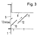
- the device for heating and / or cooling air has a housing 1 which forms an air duct 2, the cross section of which remains the same over the entire length of the housing except for a cross-sectional constriction.
- the air flows through an inlet 3 in the housing and is moved by a fan 4 in the direction of arrow 5.
- the device or the housing 1 can also be connected to the outlet of an air duct, not shown, which supplies the device with air.
- the air outlet 7 is either surrounded by the end of the housing 1 or a frame 8, which can be part of the housing 1.
- the frame 8 can also be a part which is fastened in front of the housing part and which contains the heat exchanger 6 and in particular the fan 4.
- the housing 1, or behind the housing area, which contains the heat exchanger air inlet openings through the room air into the interior of the device and thus into the air flow that comes out of the heat exchanger exit.
- air inlet openings In the direction of flow in front of the air inlet openings there is a cross-sectional constriction which constricts the air flow coming from the heat exchanger 6 and thus increases the flow speed. Since the air inlet openings are located directly behind this cross-sectional constriction, the underpressure generated by the cross-sectional constriction leads to intake of room air through the air inlet openings 9, so that room air enters the main air flow through the openings 9 Device is mixed and emerges from the air outlet 7 in the mixed state.
- the cross-sectional constriction is formed by a fixed guide plate 10, which is fastened to the side of the housing wall 1 near the opening 9 and projects into the interior of the housing and thus into the main air flow at an inclination of 30 to 60 degrees, in particular 45 degrees .
- a rigid or movable guide plate 10 as a surface part, a hollow body or profile can also form the narrowing of the cross section at this point. It is also sufficient that the housing wall is bent inwards.
- a movable air guiding part 11 is rotatably (alternatively and / or displaceably) mounted in the housing in the region of the cross-sectional constriction near the opening 9 and can take the position shown in FIG. 3.
- the air guide 11 is parallel to the baffle 10 at a distance from the baffle, so that a channel 12 is formed between the air baffle 11 and baffle 10, which generates a support flow that sucking in room air, especially at the start of the work Device supported.
- the air outlet speed changes depending on the position of the baffle.
- the air guiding part 11 can be rotated into different positions as required or moved in an embodiment not shown in order to change the air speed.
- the housing has a rectangular cross section.
- other cross-sectional shapes in particular a circular cross-sectional shape, are also possible.
- the number of air inlet openings 9 can vary depending on the type and size of the openings and also on the intended use of the device.
- two opposing air inlet openings are provided in two opposing walls of the housing.
- an intermediate part between the air outlet or the frame 8 and the main housing part 1 can be attached.
- the housing can also have an extension to form the air inlet openings.
Landscapes
- Engineering & Computer Science (AREA)
- Chemical & Material Sciences (AREA)
- Combustion & Propulsion (AREA)
- Mechanical Engineering (AREA)
- General Engineering & Computer Science (AREA)
- Cooling Or The Like Of Electrical Apparatus (AREA)
- Heating, Cooling, Or Curing Plastics Or The Like In General (AREA)
- Central Air Conditioning (AREA)
- Non-Silver Salt Photosensitive Materials And Non-Silver Salt Photography (AREA)
- Air-Flow Control Members (AREA)
Claims (11)
- Dispositif pour le chauffage et/ou le refroidissement d'air, avec un échangeur de chaleur (6) traversé par de l'air qui est disposé dans un carter (1) qui forme un canal (2) pour le flux d'air, le carter formant à son extrémité une sortie d'air (7) dans laquelle et/ou devant laquelle sont fixées des lamelles (8) pour le guidage du flux d'air sortant,
caractérisé en ce que- l'air s'écoule également au centre du canal (2),- au moins une ouverture d'entrée d'air (9) est disposée, dans la zone entre la sortie d'air (7) et l'échangeur de chaleur (6) dans la paroi latérale du carter et que le canal (2) possède, immédiatement avant l'ouverture d'entrée d'air, un étranglement en section transversale,- sensiblement à hauteur de l'ouverture d'entrée d'air (9) est disposée au moins une pièce de guidage d'air (11) qui fait saillie dans le flux d'air du canal (2) plus loin que l'étranglement en section transversale (Q) et est un étranglement supplémentaire plus fort du canal (2) et- la pièce de guidage d'air (11) forme, avec la face intérieure de l'étranglement en section transversale, un canal (12) dirigé vers l'intérieur qui est traversé par l'air du canal (2). - Dispositif selon la revendication 1,
caractérisé en ce que l'étranglement en section transversale est formé par la zone de paroi du carter (1) qui délimite par un bord l'ouverture d'entrée d'air (9). - Dispositif selon la revendication 1,
caractérisé en ce que l'étranglement en section transversale est formé par une pièce de surface (10), un corps creux ou un profilé qui fait saillie à l'intérieur du canal (2) et forme un bord de l'ouverture d'entrée d'air (9). - Dispositif selon la revendication 2 ou 3,
caractérisé en ce que la face intérieure de l'étranglement en section transversale guide le flux d'air dans le canal (2) et la face extérieure de l'étranglement en section transversale guide le flux d'air entrant à travers l'ouverture d'entrée d'air (9). - Dispositif selon l'une des revendications précédentes, caractérisé en ce que la pièce de guidage d'air (11) est mobile parallèlement à l'étranglement en section transversale.
- Dispositif selon la revendication 5, caractérisé en ce que la pièce de guidage d'air (11) est
ajustable en diverses positions - Dispositif selon la revendication 6, caractérisé en ce que la pièce de guidage d'air (11) est
réglable en rotation autour de son axe longitudinal. - Dispositif selon l'une des revendications précédentes,
caractérisé en ce qu'une pièce intermédiaire, qui présente l'ouverture d'entrée d'air (9), est disposée dans le carter entre la sortie d'air (7) et l'échangeur de chaleur (6). - Dispositif selon l'une des revendications précédentes 1 à 8,
caractérisé en ce que le carter (1) forme, entre la sortie d'air (7) et l'échangeur de chaleur (6), un prolongement qui présente l'ouverture d'entrée d'air (9). - Dispositif selon l'une des revendications précédentes,
caractérisé en ce qu'au moins une surface latérale de l'étranglement en section transversale qui guide l'air forme avec la direction principale d'écoulement d'air un angle de 30 à 60 degrés, en particulier un angle de 45°. - Dispositif selon l'une des revendications précédentes,
caractérisé en ce que le carter (1) présente sur chacune d'au moins deux faces opposées l'une à l'autre une ouverture d'entrée d'air (9).
Applications Claiming Priority (2)
| Application Number | Priority Date | Filing Date | Title |
|---|---|---|---|
| DE4133734A DE4133734A1 (de) | 1991-10-11 | 1991-10-11 | Luftheiz- und/oder kuehlgeraet |
| DE4133734 | 1991-10-11 |
Publications (3)
| Publication Number | Publication Date |
|---|---|
| EP0536498A2 EP0536498A2 (fr) | 1993-04-14 |
| EP0536498A3 EP0536498A3 (fr) | 1994-03-02 |
| EP0536498B1 true EP0536498B1 (fr) | 1995-02-08 |
Family
ID=6442515
Family Applications (1)
| Application Number | Title | Priority Date | Filing Date |
|---|---|---|---|
| EP92113407A Expired - Lifetime EP0536498B1 (fr) | 1991-10-11 | 1992-08-06 | Appareil de chauffage et/ou de refroidissement |
Country Status (6)
| Country | Link |
|---|---|
| EP (1) | EP0536498B1 (fr) |
| AT (1) | ATE118267T1 (fr) |
| DE (2) | DE4133734A1 (fr) |
| DK (1) | DK0536498T3 (fr) |
| ES (1) | ES2068659T3 (fr) |
| GR (1) | GR3015051T3 (fr) |
Families Citing this family (5)
| Publication number | Priority date | Publication date | Assignee | Title |
|---|---|---|---|---|
| DE19822173B4 (de) * | 1998-05-16 | 2007-02-08 | Behr Gmbh & Co. Kg | Vorrichtung zur Heizung und/oder Klimatisierung eines Fahrzeuginnenraumes |
| DE19834269C2 (de) * | 1998-07-30 | 2000-09-28 | Ltg Holding Gmbh | Ventilatorkonvektor |
| DE10113521A1 (de) * | 2001-03-20 | 2002-10-02 | Wolf Gmbh | Vorrichtung zum Leiten eines Luftstroms durch Lamellen |
| DE10140190B4 (de) * | 2001-08-22 | 2004-10-14 | Patentwerk.De Gmbh | Raum-Aufheizeinrichtung mit Heizkörper und Luftausrichtungseinheit |
| DE102006027320A1 (de) * | 2006-06-13 | 2007-12-20 | Gea Happel Klimatechnik Produktions- Und Servicegesellschaft Mbh | Auslass eines Gebläsekonvektors |
Family Cites Families (14)
| Publication number | Priority date | Publication date | Assignee | Title |
|---|---|---|---|---|
| US2275295A (en) * | 1939-08-12 | 1942-03-03 | George H Greenway | Air conditioning unit |
| US2345536A (en) * | 1942-05-16 | 1944-03-28 | B F Sturtevant Co | Heat exchange unit |
| US2674177A (en) * | 1951-08-04 | 1954-04-06 | C A Olson Mfg Company | Recirculating entrainment device for forced air heating systems |
| DE1295168B (de) * | 1964-01-09 | 1969-05-14 | Eugen Laible Kg Badeapp Fabrik | Kalt- und Warmluftkonvektor |
| US3604625A (en) * | 1969-11-03 | 1971-09-14 | Dynamics Corp America | Airflow mixing device for air conditioning systems |
| US3638679A (en) * | 1969-11-20 | 1972-02-01 | Dimiter Gorchev | Induction system having variable primary volume and variable induction |
| US3981326A (en) * | 1974-02-28 | 1976-09-21 | Mitco Corporation | Induction mixing nozzle |
| ZA771500B (en) * | 1977-03-11 | 1978-06-28 | Ventline Mfg Ltd | Improvements in or relating to air conditioning |
| US4657178A (en) * | 1980-09-05 | 1987-04-14 | Camp Dresser & Mckee | Mixing box |
| US4448111A (en) * | 1981-01-02 | 1984-05-15 | Doherty Robert | Variable venturi, variable volume, air induction input for an air conditioning system |
| GB2127145B (en) * | 1982-09-14 | 1987-04-29 | Flaekt Ab | Air induction ventilators |
| DE3638614A1 (de) * | 1986-11-12 | 1988-05-26 | Happel Gmbh & Co | Vorrichtung zum leiten eines luftstroms |
| DE3638616A1 (de) * | 1986-11-12 | 1988-05-26 | Happel Gmbh & Co | Vorrichtung zum leiten eines luftstroms |
| DE3644590A1 (de) * | 1986-12-27 | 1988-07-14 | Ltg Lufttechnische Gmbh | Lufttechnisches geraet zum einblasen von zuluft in einen raum |
-
1991
- 1991-10-11 DE DE4133734A patent/DE4133734A1/de not_active Withdrawn
-
1992
- 1992-08-06 AT AT92113407T patent/ATE118267T1/de not_active IP Right Cessation
- 1992-08-06 DK DK92113407.8T patent/DK0536498T3/da active
- 1992-08-06 DE DE59201358T patent/DE59201358D1/de not_active Expired - Fee Related
- 1992-08-06 ES ES92113407T patent/ES2068659T3/es not_active Expired - Lifetime
- 1992-08-06 EP EP92113407A patent/EP0536498B1/fr not_active Expired - Lifetime
-
1995
- 1995-02-15 GR GR950400289T patent/GR3015051T3/el unknown
Also Published As
| Publication number | Publication date |
|---|---|
| DE4133734A1 (de) | 1993-04-22 |
| DK0536498T3 (da) | 1995-07-10 |
| DE59201358D1 (de) | 1995-03-23 |
| EP0536498A3 (fr) | 1994-03-02 |
| ATE118267T1 (de) | 1995-02-15 |
| EP0536498A2 (fr) | 1993-04-14 |
| ES2068659T3 (es) | 1995-04-16 |
| GR3015051T3 (en) | 1995-05-31 |
Similar Documents
| Publication | Publication Date | Title |
|---|---|---|
| EP3397782B1 (fr) | Dispositif de traitement de pièces métalliques avec du gaz de refroidissement | |
| EP0536498B1 (fr) | Appareil de chauffage et/ou de refroidissement | |
| DE102018214560A1 (de) | Luftauslass | |
| DE102009030008A1 (de) | Tomographiegerät mit einem Ringkanal und mit mindestens einem Entlüftungselement zum Abführen eines in dem Ringkanal strömenden Luftstroms | |
| DE3503089C2 (fr) | ||
| EP0267485B1 (fr) | Dispositif pour diriger un courant d'air | |
| DE212013000156U1 (de) | Vorrichtungen zum Beruhigen eines Luftstroms | |
| DE1154252B (de) | Abschirmung von Raumoeffnungen durch einen Luftschleier | |
| DE102019127256A1 (de) | Auslassventil | |
| DE69818024T2 (de) | Kühllamelle für eine vorrichtung zum herstellen von fasern | |
| DE3638614A1 (de) | Vorrichtung zum leiten eines luftstroms | |
| DE856980C (de) | Vorrichtung zum Umlenken und gleichmaessigen Verteilen eines stroemenden Mediums | |
| DE2708809C2 (fr) | ||
| DE3914242C2 (de) | Einrichtung zum Erwärmen und/oder Kühlen von Räumen | |
| EP0392453B1 (fr) | Séparateur centrifuge | |
| EP0706013B1 (fr) | Echangeur de chaleur à gaz | |
| AT207088B (de) | Abschirmung von Raumöffnungen durch einen Luftschleier | |
| DE4323080C1 (de) | Belüftungsvorrichtung | |
| DE19510233B4 (de) | Extruder | |
| DE3306571A1 (de) | Hydraulisch betaetigter spannzylinder fuer spanneinrichtungen an einer rotierenden spindel, insbesondere drehmaschinenspindel | |
| DE4039170C2 (de) | Luftheizer | |
| DE69200335T2 (de) | Drallauslass. | |
| DE1751223C3 (de) | Wirbelrohr zum Kühlen eines Körpers | |
| DE1290650B (de) | Vorrichtung zum Mischen und Durchfuehren von Verbrennungsreaktionen | |
| DE19844691A1 (de) | Vorrichtung zur Wärmebehandlung einer breitgeführten Warenbahn |
Legal Events
| Date | Code | Title | Description |
|---|---|---|---|
| PUAI | Public reference made under article 153(3) epc to a published international application that has entered the european phase |
Free format text: ORIGINAL CODE: 0009012 |
|
| AK | Designated contracting states |
Kind code of ref document: A2 Designated state(s): AT BE CH DE DK ES FR GB GR IE IT LI LU NL PT SE |
|
| PUAL | Search report despatched |
Free format text: ORIGINAL CODE: 0009013 |
|
| AK | Designated contracting states |
Kind code of ref document: A3 Designated state(s): AT BE CH DE DK ES FR GB GR IE IT LI LU NL PT SE |
|
| 17P | Request for examination filed |
Effective date: 19940217 |
|
| 17Q | First examination report despatched |
Effective date: 19940425 |
|
| GRAA | (expected) grant |
Free format text: ORIGINAL CODE: 0009210 |
|
| AK | Designated contracting states |
Kind code of ref document: B1 Designated state(s): AT BE CH DE DK ES FR GB GR IE IT LI LU NL PT SE |
|
| REF | Corresponds to: |
Ref document number: 118267 Country of ref document: AT Date of ref document: 19950215 Kind code of ref document: T |
|
| ET | Fr: translation filed | ||
| REG | Reference to a national code |
Ref country code: IE Ref legal event code: FG4D Free format text: 62836 |
|
| REF | Corresponds to: |
Ref document number: 59201358 Country of ref document: DE Date of ref document: 19950323 |
|
| ITF | It: translation for a ep patent filed | ||
| GBT | Gb: translation of ep patent filed (gb section 77(6)(a)/1977) |
Effective date: 19950223 |
|
| REG | Reference to a national code |
Ref country code: ES Ref legal event code: FG2A Ref document number: 2068659 Country of ref document: ES Kind code of ref document: T3 |
|
| REG | Reference to a national code |
Ref country code: GR Ref legal event code: FG4A Free format text: 3015051 |
|
| REG | Reference to a national code |
Ref country code: DK Ref legal event code: T3 |
|
| PLBE | No opposition filed within time limit |
Free format text: ORIGINAL CODE: 0009261 |
|
| 26N | No opposition filed | ||
| PGFP | Annual fee paid to national office [announced via postgrant information from national office to epo] |
Ref country code: PT Payment date: 19970528 Year of fee payment: 6 |
|
| PGFP | Annual fee paid to national office [announced via postgrant information from national office to epo] |
Ref country code: IE Payment date: 19970604 Year of fee payment: 6 |
|
| PGFP | Annual fee paid to national office [announced via postgrant information from national office to epo] |
Ref country code: GR Payment date: 19970612 Year of fee payment: 6 |
|
| PGFP | Annual fee paid to national office [announced via postgrant information from national office to epo] |
Ref country code: FR Payment date: 19970723 Year of fee payment: 6 |
|
| PGFP | Annual fee paid to national office [announced via postgrant information from national office to epo] |
Ref country code: GB Payment date: 19970724 Year of fee payment: 6 Ref country code: CH Payment date: 19970724 Year of fee payment: 6 |
|
| PGFP | Annual fee paid to national office [announced via postgrant information from national office to epo] |
Ref country code: LU Payment date: 19970728 Year of fee payment: 6 |
|
| PGFP | Annual fee paid to national office [announced via postgrant information from national office to epo] |
Ref country code: SE Payment date: 19970729 Year of fee payment: 6 Ref country code: AT Payment date: 19970729 Year of fee payment: 6 |
|
| PGFP | Annual fee paid to national office [announced via postgrant information from national office to epo] |
Ref country code: ES Payment date: 19970808 Year of fee payment: 6 Ref country code: BE Payment date: 19970808 Year of fee payment: 6 |
|
| PGFP | Annual fee paid to national office [announced via postgrant information from national office to epo] |
Ref country code: DK Payment date: 19970818 Year of fee payment: 6 |
|
| PGFP | Annual fee paid to national office [announced via postgrant information from national office to epo] |
Ref country code: NL Payment date: 19970831 Year of fee payment: 6 |
|
| PGFP | Annual fee paid to national office [announced via postgrant information from national office to epo] |
Ref country code: DE Payment date: 19971023 Year of fee payment: 6 |
|
| PG25 | Lapsed in a contracting state [announced via postgrant information from national office to epo] |
Ref country code: LU Free format text: LAPSE BECAUSE OF NON-PAYMENT OF DUE FEES Effective date: 19980806 Ref country code: IE Free format text: LAPSE BECAUSE OF NON-PAYMENT OF DUE FEES Effective date: 19980806 Ref country code: GB Free format text: LAPSE BECAUSE OF NON-PAYMENT OF DUE FEES Effective date: 19980806 Ref country code: AT Free format text: LAPSE BECAUSE OF NON-PAYMENT OF DUE FEES Effective date: 19980806 |
|
| PG25 | Lapsed in a contracting state [announced via postgrant information from national office to epo] |
Ref country code: SE Free format text: LAPSE BECAUSE OF NON-PAYMENT OF DUE FEES Effective date: 19980807 Ref country code: ES Free format text: LAPSE BECAUSE OF THE APPLICANT RENOUNCES Effective date: 19980807 |
|
| PG25 | Lapsed in a contracting state [announced via postgrant information from national office to epo] |
Ref country code: LI Free format text: LAPSE BECAUSE OF NON-PAYMENT OF DUE FEES Effective date: 19980831 Ref country code: GR Free format text: LAPSE BECAUSE OF NON-PAYMENT OF DUE FEES Effective date: 19980831 Ref country code: DK Free format text: LAPSE BECAUSE OF NON-PAYMENT OF DUE FEES Effective date: 19980831 Ref country code: CH Free format text: LAPSE BECAUSE OF NON-PAYMENT OF DUE FEES Effective date: 19980831 Ref country code: BE Free format text: LAPSE BECAUSE OF NON-PAYMENT OF DUE FEES Effective date: 19980831 |
|
| BERE | Be: lapsed |
Owner name: GEA HAPPEL KLIMATECHNIK G.M.B.H. Effective date: 19980831 |
|
| PG25 | Lapsed in a contracting state [announced via postgrant information from national office to epo] |
Ref country code: PT Free format text: LAPSE BECAUSE OF NON-PAYMENT OF DUE FEES Effective date: 19990228 |
|
| PG25 | Lapsed in a contracting state [announced via postgrant information from national office to epo] |
Ref country code: NL Free format text: LAPSE BECAUSE OF NON-PAYMENT OF DUE FEES Effective date: 19990301 |
|
| GBPC | Gb: european patent ceased through non-payment of renewal fee |
Effective date: 19980806 |
|
| REG | Reference to a national code |
Ref country code: CH Ref legal event code: PL |
|
| PG25 | Lapsed in a contracting state [announced via postgrant information from national office to epo] |
Ref country code: FR Free format text: LAPSE BECAUSE OF NON-PAYMENT OF DUE FEES Effective date: 19990430 |
|
| EUG | Se: european patent has lapsed |
Ref document number: 92113407.8 |
|
| NLV4 | Nl: lapsed or anulled due to non-payment of the annual fee |
Effective date: 19990301 |
|
| PG25 | Lapsed in a contracting state [announced via postgrant information from national office to epo] |
Ref country code: DE Free format text: LAPSE BECAUSE OF NON-PAYMENT OF DUE FEES Effective date: 19990601 |
|
| REG | Reference to a national code |
Ref country code: FR Ref legal event code: ST |
|
| REG | Reference to a national code |
Ref country code: PT Ref legal event code: MM4A Free format text: LAPSE DUE TO NON-PAYMENT OF FEES Effective date: 19990228 |
|
| REG | Reference to a national code |
Ref country code: DK Ref legal event code: EBP |
|
| REG | Reference to a national code |
Ref country code: ES Ref legal event code: FD2A Effective date: 20001102 |
|
| PG25 | Lapsed in a contracting state [announced via postgrant information from national office to epo] |
Ref country code: IT Free format text: LAPSE BECAUSE OF NON-PAYMENT OF DUE FEES;WARNING: LAPSES OF ITALIAN PATENTS WITH EFFECTIVE DATE BEFORE 2007 MAY HAVE OCCURRED AT ANY TIME BEFORE 2007. THE CORRECT EFFECTIVE DATE MAY BE DIFFERENT FROM THE ONE RECORDED. Effective date: 20050806 |