EP0535409B1 - Amortisseur hydraulique pour véhicule automobile - Google Patents
Amortisseur hydraulique pour véhicule automobile Download PDFInfo
- Publication number
- EP0535409B1 EP0535409B1 EP92115324A EP92115324A EP0535409B1 EP 0535409 B1 EP0535409 B1 EP 0535409B1 EP 92115324 A EP92115324 A EP 92115324A EP 92115324 A EP92115324 A EP 92115324A EP 0535409 B1 EP0535409 B1 EP 0535409B1
- Authority
- EP
- European Patent Office
- Prior art keywords
- shock absorber
- absorber according
- annular part
- cylinder
- annular
- Prior art date
- Legal status (The legal status is an assumption and is not a legal conclusion. Google has not performed a legal analysis and makes no representation as to the accuracy of the status listed.)
- Expired - Lifetime
Links
- 239000006096 absorbing agent Substances 0.000 title claims description 27
- 230000035939 shock Effects 0.000 title claims description 27
- 125000006850 spacer group Chemical group 0.000 claims description 33
- 238000013016 damping Methods 0.000 claims description 23
- 238000007789 sealing Methods 0.000 claims description 5
- 239000012530 fluid Substances 0.000 claims description 3
- 239000002184 metal Substances 0.000 claims description 3
- 238000013022 venting Methods 0.000 claims description 3
- 230000001154 acute effect Effects 0.000 claims 1
- 238000007373 indentation Methods 0.000 claims 1
- 238000000465 moulding Methods 0.000 description 9
- 238000004519 manufacturing process Methods 0.000 description 3
- 238000005553 drilling Methods 0.000 description 2
- 238000009423 ventilation Methods 0.000 description 2
- 239000011324 bead Substances 0.000 description 1
- 238000005266 casting Methods 0.000 description 1
- 230000006835 compression Effects 0.000 description 1
- 238000007906 compression Methods 0.000 description 1
- 238000010276 construction Methods 0.000 description 1
- 230000008595 infiltration Effects 0.000 description 1
- 238000001764 infiltration Methods 0.000 description 1
- 238000003780 insertion Methods 0.000 description 1
- 230000037431 insertion Effects 0.000 description 1
- 238000003754 machining Methods 0.000 description 1
- 238000005245 sintering Methods 0.000 description 1
Images


Classifications
-
- F—MECHANICAL ENGINEERING; LIGHTING; HEATING; WEAPONS; BLASTING
- F16—ENGINEERING ELEMENTS AND UNITS; GENERAL MEASURES FOR PRODUCING AND MAINTAINING EFFECTIVE FUNCTIONING OF MACHINES OR INSTALLATIONS; THERMAL INSULATION IN GENERAL
- F16F—SPRINGS; SHOCK-ABSORBERS; MEANS FOR DAMPING VIBRATION
- F16F9/00—Springs, vibration-dampers, shock-absorbers, or similarly-constructed movement-dampers using a fluid or the equivalent as damping medium
- F16F9/32—Details
- F16F9/36—Special sealings, including sealings or guides for piston-rods
- F16F9/362—Combination of sealing and guide arrangements for piston rods
- F16F9/363—Combination of sealing and guide arrangements for piston rods the guide being mounted between the piston and the sealing, enabling lubrication of the guide
Definitions
- the invention relates to a Hydraulic vibration damper for motor vehicles with a damper cylinder containing damping fluid, a piston rod which moves back and forth in it and carries a damping piston, and a guide closure arranged at the end penetrated by the piston rod and having a trailing oil relief channel and having a cylindrical guide part for the piston rod and an oil seal contacting the piston rod and a support and spacer unit formed from a plurality of sheet-metal-formed parts, which supports the cylindrical guide part of the piston rod on the damper cylinder radially and axially, a first ring-shaped part having an essentially cup-shaped cross section.
- German laid-open specification DE 40 30 788 describes a guide lock for a two-tube vibration damper, which consists of a tubular rod guide part, an oil seal and a pressed plate part. An additional stop is arranged more colorfully to intercept the pull stop forces.
- the guide lock improves the disadvantages of known piston rod guides, but is not applicable to single-tube vibration dampers with higher demands on the guide package, in particular the rigidity of the guide lock against the load is not sufficient.
- the support and spacer unit has at least one further ring shaped part partially overlapping the ring shaped part, the ring shaped part closing the ring shaped part to form a cavity.
- the support and spacer unit holds the oil seal surrounding the piston rod on its side facing the piston rod.
- the support and spacer unit which is formed from a first and a second shaped ring part, has a cross section which surrounds a cavity and is of any shape and which in one configuration is essentially rectangular.
- the support and spacer unit consists of a first ring molded part with a cup-shaped cross section and a second ring molded part closing the first ring molded part and rests on the cylindrical guide part of the piston rod, but other designs are also possible.
- the support and spacer unit has a further ring-shaped part designed as an end cap, which seals the damper cylinder in a sealing manner.
- the first ring shaped part has a design for the single-tube damper a bore that forms the trailing oil relief channel from the oil seal contracting the piston rod to the working space of the vibration damper.
- the second ring-shaped part closing the first ring-shaped part extends over the wall of the damper cylinder at intervals and is supported on the outer cylinder and / or the end cap.
- the cup-shaped first ring shaped part is supported on the inner wall of the damper cylinder and the supporting part engages around the damper cylinder.
- the first or second molded ring part has a vent hole which forms a channel between the annular space of the oil seal and the compensation space formed by the outer cylinder, the channel being closed on the compensation space side by a check valve.
- a check valve Different designs of the check valve are possible.
- the bottom part of the first ring-shaped part which has an essentially cup-shaped cross section, is cranked at least once, as a result of which, in the case of single-tube vibration dampers, there is greater stability with respect to the forces arising from the insertion and extension stroke of the piston rod.
- the guide part of the piston rod can thus be supported on the damper cylinder and on the outer cylinder, since the part bent upwards lies against the damper cylinder.
- the second ring shaped part holds the oil seal contacting the piston rod and seals the damper cylinder or the outer cylinder of the vibration damper on the side facing away from the piston rod, overlapping the first ring shaped part by means of a further seal.
- the support and spacer unit is fixed in the cylinder by the fully or partially flanged edge of the damper cylinder and / or by means of sinks or a constriction in the wall of the damper cylinder fixed.
- the outer cylinder fixes them accordingly.
- the guide lock according to the invention has the advantage over known piston rod guides for vibration dampers that its ring shaped parts are easy to manufacture, introduce a small mass into the vibration damper and can be easily installed in the vibration damper, since the guide lock can be prefabricated as a complete assembly with a guide part and oil seal. The tensile stop forces occurring in the rebound stage and also the stop forces of the compression stage are absorbed by the guide lock.
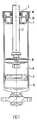
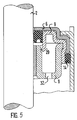
- the hydraulic single-tube vibration damper shown in FIG. 1 essentially consists of a damper cylinder 1 containing damping fluid, which is closed by a guide lock 20 and a damper piston 15 connected to the piston rod 2 a working space 16, which is separated by the separating piston 17 from the gas-filled compensation space 19, which serves to compensate for the increase or decrease in volume in the hydraulic working space 16 by the retracting or extending internal volume of the piston rod 2.
- the piston rod 2 slides through the guide plug 20 and is in contact with an oil seal 4 to seal the opening of the cylinder assembly.
- An annular plate 18 encompassing the piston rod 2 is also fastened above the guide closure 20, for example by means of a clamped or welded connection.
- the ring plate 18 serves as a rubber buffer stop at the end of the entry stroke.
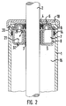
- Fig. 2 shows a guide closure according to the invention, consisting of a cylindrical guide part 3, which guides the in and out strokes of the piston rod 2, a support and spacer unit 5 made of sheet metal parts, which the guide part 3 on the inner wall of the damper cylinder 1 and the Supporting end cap 6, and an oil seal 4 arranged above the guide part 3 and supported or held by the support and spacer unit 5.
- the ring-shaped support and spacer unit 5 consisting of two ring-shaped parts 8, 9 has a rectangular cross section enclosing a cavity 7. wherein the ring-shaped part 9 partially overlaps the cup-shaped ring-shaped part 8 on the guide part 3 and on the wall of the damper cylinder 1 and rests on the outer wall of the guide part 3.
- the trailing oil relief channel 21 runs from the oil seal 4 via a bore or slots 29 in the ring-shaped part 9, the cavity 7 and a bore 32 in the bottom of the cup-shaped ring part 8 to the working space 16.
- an annular seal 14 is fitted on the outer edge of the end cap 6 between the ring-shaped part 8 and the wall of the damper cylinder 1.
- the ring plate 18 which serves as a rubber buffer stop, lies on the parts of the edge 33 which are not flanged.
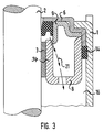
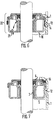
- FIG. 3 shows a support and spacer unit in which the ring-shaped part 9 closes the cup-shaped ring-shaped part 8, but does not overlap.
- the inner part 34 of the ring-shaped part 8 thus bears against the guide part 3 of the piston rod 2.
- part 34 of ring-shaped part 8 is coated on its side facing piston rod 2 and serves as a piston rod guide, so that guide part 3 could be omitted.
- the ring-shaped part 9 is supported only on the end cap 6, which is shaped in such a way that it abuts the inner wall of the damper cylinder 1 and the ring-shaped part 8 partially overlaps.
- a seal 14 was arranged between the wall of the damper cylinder 1 and the ring-shaped part 8, which comes to rest on the end face of the end cap 6.
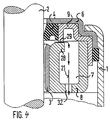
- the support and spacer unit consists of the cup-shaped ring-shaped part 8, the wall of which lies against the guide part 3 has a short, inwardly bent part 28 on which the ring-shaped part 9 is supported.
- the ring molding 8 is overlapped by the ring molding 9, which also abuts the end cap 6 carrying the oil seal 4.
- the oil drag relief channel 21 is formed by slots 29 in the ring molding 9, the cavity 7 and a bore 32 in the bottom of the ring molding 8.
- the second ring-shaped part 9 and the first ring-shaped part 6 are shaped such that an annular space is formed on the piston rod 2 above the guide part 3, in which the oil seal 4 held by the ring-shaped parts is located.
- FIG. 5 shows another possible variant of a support and spacer unit, in which the side of the end cap 6 overlapping the ring-shaped part 9 is caulked against the ring-shaped part 9 in order to pretension the seal 14.
- the slots 29 for the Relief channel as well as the bore 32 were incorporated into the ring molding 8.
- FIG. 1 Another possibility of prestressing the seal 14 required for sealing the working space 16 and the trailing oil relief channel 21 is shown in FIG.
- the seal 14 which is designed as an annular seal, was arranged above the support and spacer unit 5 between the completely bent edge of the damper cylinder 1 and the stepped end cap 6.
- the constriction 12 on the wall of the damper cylinder 1 only serves to hold the guide part 3 and the support and spacer unit 5 in the damper cylinder 1.
- FIG. 8 Another type of fixation of the guide closure is shown in Fig. 8, in which in the wall of the damper cylinder 1 below the guide closure on the circumference, sinks 11 are introduced, on which the ring-shaped part 8 of the support and spacer unit comes to rest.
- the upper fixation of the guide lock is realized by the completely cranked edge 33 of the damper cylinder 1.
- the trailing oil relief duct runs from the oil seal 4 via the annular space 10, a passage 29, the cavity 7 and a bore 32 to the working space 16.
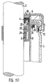
- Fig. 9 shows a two-tube damper, which consists of a working space 16, which is formed by the damper cylinder 1 and is delimited at the lower end by the bottom valve 30 and at the top by the guide lock 20.
- the damper cylinder 1 is surrounded by an outer cylinder 23.
- the compensation space is located in the annular space thus formed 19, which is about half filled with oil, while the working space 16 has full oil.
- the outer cylinder 23 connects the guide lock 20 to the bottom cap 31 supporting the bottom valve.
- Fig. 10 the guide closure for a two-tube damper with three ring shaped parts is described in more detail.
- the cup-shaped ring-shaped part 8 rests with its inner wall on the guide part 3 of the piston rod 2.
- the radially outer part 24 of the ring-shaped part 8 encompasses the upper edge of the damper cylinder 1. Because of the larger radius of the piston rod 2 of a shock absorber, the distance between the inner part 34 and the outer part 24 of the ring-shaped part 8 is dimensioned such that the cup-shaped ring-shaped part 8 passes through Fit of the side part 37 of the ring molding 9 is closed.
- the ring-shaped part 9 also bridges the wall of the damper cylinder 1 at intervals and is supported on the inner wall of the outer cylinder 23 and the end cap 6 closing the damper cylinder and the outer cylinder.
- the end cap 6 also carries the oil seal 4 encompassing the piston rod 2 and lying against its circumference 4.
- the vent hole 25 provided in the ring shaped part 9 and the part of the ring shaped part 8 between the ring shaped part 9 and the part of the ring shaped part 8 encompassing the upper edge of the damper cylinder 1 ensure effective ventilation provided elastic valve ring 26.
- the outer cylinder 23 is sealed by means of the seal 27 between the inner wall of the outer cylinder 23 and the support and spacer unit. To fix the guide lock in the outer cylinder 23, it has a circumferential constriction 12 on which the support and spacer unit comes to rest.
- a ring plate 18, which surrounds the piston rod 2 and serves as a rubber buffer stop, is fastened above the guide closure.
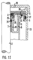
- the cup-shaped ring-shaped part 8 also bears against the guide part 3 and carries a high-pressure seal 35 above it on its side facing the piston rod 2. With its part 24, the ring-shaped part 8 also engages around the damper cylinder 1.
- the ring-shaped part 9 closes the cup-shaped ring-shaped part 8 by being closed is supported on or on the inner part 34 of the ring-shaped part 8 and rests on the angled part 24. In the area of the outer cylinder 23, it is supported on the end cap 6.
- the oil seal 4 designed as a low-pressure seal is held by the ring-shaped part 9.
- the venting channel is formed by the bore 36 in the annular molded part 8 and the ventilation opening 25 designed as a slot or bore, as well as the check valve 26 located between the part 24 encompassing the damper cylinder 1 and the annular molded part 9.
- the support and spacer unit 5 according to the invention can be installed together with the oil seal 4 as a preassembled unit.
Landscapes
- Engineering & Computer Science (AREA)
- General Engineering & Computer Science (AREA)
- Mechanical Engineering (AREA)
- Fluid-Damping Devices (AREA)
Claims (25)
- Amortisseur hydraulique pour véhicule, comportant un cylindre d'amortisseur (1) contenant un fluide d'amortissement, une tige de piston (2) se déplaçant en va-et-vient dans celui-ci et portant un piston d'amortissement (15), et une fermeture de guidage (20) disposée à l'extrémité traversée par la tige de piston (2), présentant un canal de détente de l'huile entraînée et comportant une pièce de guidage (3) de forme cylindrique pour la tige de piston (2), un joint étanche à l'huile (4) en contact avec la tige de piston et une unité de soutien et d'écartement (5) formée de plusieurs pièces en tôle façonnées, qui soutient radialement et axialement la pièce de guidage (3) de forme cylindrique de la tige de piston (2) sur le cylindre d'amortisseur (1), dans lequel une première pièce de forme annulaire (8) présente une section transversale essentiellement en forme de cuvette, caractérisé en ce que l'unité de soutien et d'écartement (5) présente au moins une autre pièce de forme annulaire (9,6) recouvrant partiellement la pièce de forme annulaire (8), et en ce que la pièce de forme annulaire (9) ferme la pièce de forme annulaire (8) pour former une chambre creuse (7).
- Amortisseur selon la revendication 1, caractérisé en ce que, de son côté tourné vers la tige de piston (2), l'unité de soutien et d'écartement (5) maintient et/ou porte le joint étanche à l'huile (4) entourant la tige de piston, au-dessus ou en dessous de la pièce de guidage (3) de forme tubulaire.
- Amortisseur selon la revendication 2, caractérisé en ce que l'unité de soutien et d'écartement (5) est configurée en forme d'anneau, avec une section transversale essentiellement rectangulaire.
- Amortisseur selon l'une des revendications 1-3, caractérisé en ce que la seconde pièce de forme annulaire (9) recouvre partiellement la pièce de forme annulaire (8).
- Amortisseur selon l'une des revendications 1 à 4, caractérisé en ce qu'une pièce de forme annulaire entourant les pièces de forme annulaire (8, 9) est configurée comme capot d'extrémité (6) fermant le cylindre d'amortisseur (1).
- Amortisseur selon la revendication 5, caractérisé en ce que la seconde pièce de forme annulaire (9) est ajuste au capot d'extrémité (6) et à la paroi extérieure de la pièce de guidage (3).
- Amortisseur selon l'une des revendications 4 à 6, caractérisé en ce que la pièce de guidage (3) est formée par une partie de la pièce de forme annulaire (9) ou de la pièce de forme annulaire (8).
- Amortisseur selon la revendication 7, caractérisé en ce que la pièce de forme annulaire (8) en forme de cuvette est ajusté à la paroi extérieure de la pièce de guidage (3).
- Amortisseur selon l'une ou plusieurs des revendications 4 à 8, caractérisé en ce que la pièce de forme annulaire (9) est ajusté à la paroi intérieure du cylindre d'amortisseur (1).
- Amortisseur selon l'une ou plusieurs des revendications 4 à 8, caractérisé en ce que la pièce de forme annulaire (8) présente un alésage (29) qui forme le canal (21) de détente de l'huile entraînée entre la chambre annulaire (10) et la chambre de travail (16).
- Amortisseur selon l'une ou plusieurs des revendications 1 à 10, caractérisé en ce que l'unité de soutien et d'écartement (5) est ajustée de manière étanche à la paroi intérieure du cylindre d'amortisseur (1).
- Amortisseur selon l une ou plusieurs des revendications 1 à 8, caractérisé en ce que le cylindre d'amortisseur (1) est entouré par un cylindre extérieur (23), le capot d'extrémité (6) ferme le cylindre d'amortisseur (1) et le cylindre extérieur (23), et la pièce de forme annulaire (9) fermant la pièce de forme annulaire (8) recouvre a distance le bord supérieur du cylindre d'amortisseur (1) et s'appuie radialement et axialement contre le capot d'extrémité (6) et/ou la paroi intérieure du cylindre extérieur (23).
- Amortisseur selon l'une ou plusieurs des revendications 4 à 12, caractérise en ce que la pièce de fond (22) de la pièce de forme annulaire (8) est rabattue au moins une fois.
- Amortisseur selon la revendication 13, caractérisé en ce que le cylindre d'amortisseur (1) est entouré par un cylindre extérieur (23), la pièce de forme annulaire (9) ferme de manière étanche le cylindre d'amortisseur (1) et le cylindre extérieur (23), et la pièce de forme annulaire (8) s'appuie radialement contre la paroi intérieure du cylindre d'amortisseur (1) et du cylindre extérieur (23), tandis que la partie rabattue de la pièce de forme annulaire (8) recouvre le bord (24) du cylindre d'amortisseur (1).
- Amortisseur selon l'une ou plusieurs des revendications 13 à 14, caractérise en ce que la pièce de forme annulaire (8) ou la pièce de forme annulaire (9) présentent un alésage (25) de purge d'air qui forme un canal entre la chambre annulaire (10), le joint étanche à l'huile (4) et la chambre d'équilibrage (19) formée par le cylindre extérieur (23), tandis que le canal est fermé par une soupape anti-retour (13), du côté de la chambre d'équilibrage.
- Amortisseur selon la revendication 15, caractérisé en ce que la soupape anti-retour (13) est prévue entre la partie de la pièce de forme annulaire (8) qui entoure le bord supérieur du cylindre d'amortisseur (1) et la pièce de forme annulaire (9) formant un angle aigu avec celle-ci.
- Amortisseur selon la revendication 15 ou 16, caractérisé en ce que la soupape anti-retour (13) est une bague de soupape élastique.
- Amortisseur selon la revendication 15, caractérisé en ce que la soupape anti-retour (13) est formée par le bord (24) de la pièce de forme annulaire (8) ou par le bord (32) du cylindre d'amortisseur (1), et une bague de soupape (26) correspondant à l'alésage (25) de purge d'air.
- Amortisseur selon la revendication 15, caractérisé en ce que la soupape anti-retour (13) est formée d'une pièce annulaire (38) courbée, disposée sur la paroi intérieure de la pièce de forme annulaire (8), et d'une bague de soupape (26) correspondant au passage.
- Amortisseur selon l'une ou plusieurs des revendications 13 à 19, caractérisé en ce que le cylindre extérieur (23) est fermé de manière étanche au moyen d'un joint étanche (27) situé entre la paroi intérieure du cylindre extérieur (23) et l'unité de soutien et d'écartement (5).
- Amortisseur selon l'une ou plusieurs des revendications 1 à 20, caractérisé en ce que l'unité de soutien et d'écartement (5) sert de butée en traction.
- Amortisseur selon l'une ou plusieurs des revendications 1 à 21, caractérise en ce que la pièce de guidage (3), l'unité de soutien et d'écartement (5) et le joint étanch à l'huile (4) forment une unité pré-montée.
- Amortisseur selon l'une ou plusieurs des revendications 1 à 22, caractérisé en ce que l'unité de soutien et d'écartement (5) est maintenue contre la paroi du cylindre d'amortisseur (1) ou du cylindre extérieur (23) au moyen d'un rétrécissement (11) ou d'une gorge (12).
- Amortisseur selon la revendication 18, caractérisé en ce que le joint étanche (14, 27) est pré-serré au moyen de la gorge (12).
- Amortisseur selon l une ou plusieurs des revendications 1 à 24, caractérisé en ce que l'unité de soutien et d'écartement est fixée par le bord (33), complètement ou partiellement rabattu, du cylindre d'amortisseur (1) ou du cylindre extérieur (23).
Applications Claiming Priority (6)
| Application Number | Priority Date | Filing Date | Title |
|---|---|---|---|
| DE4132734 | 1991-10-01 | ||
| DE4132734 | 1991-10-01 | ||
| DE4135576 | 1991-10-29 | ||
| DE4135576 | 1991-10-29 | ||
| DE19924207099 DE4207099C1 (fr) | 1992-03-06 | 1992-03-06 | |
| DE4207099 | 1992-03-06 |
Publications (2)
| Publication Number | Publication Date |
|---|---|
| EP0535409A1 EP0535409A1 (fr) | 1993-04-07 |
| EP0535409B1 true EP0535409B1 (fr) | 1996-02-07 |
Family
ID=27202987
Family Applications (1)
| Application Number | Title | Priority Date | Filing Date |
|---|---|---|---|
| EP92115324A Expired - Lifetime EP0535409B1 (fr) | 1991-10-01 | 1992-09-08 | Amortisseur hydraulique pour véhicule automobile |
Country Status (3)
| Country | Link |
|---|---|
| EP (1) | EP0535409B1 (fr) |
| DE (1) | DE59205291D1 (fr) |
| ES (1) | ES2083043T3 (fr) |
Families Citing this family (17)
| Publication number | Priority date | Publication date | Assignee | Title |
|---|---|---|---|---|
| FR2695973B1 (fr) * | 1992-09-18 | 1994-11-18 | Hutchinson | Dispositif de guidage pour tige d'amortisseur. |
| DE4311101B4 (de) * | 1993-04-03 | 2004-01-15 | Zf Sachs Ag | Einteilige Blechkolbenstangenführung für einen Schwingungsdämpfer |
| ES2114358B1 (es) * | 1993-04-03 | 1999-01-01 | Fichtel & Sachs Ag | Guia de biela de chapa de una sola pieza para un amortiguador de vibraciones. |
| DE4311100B4 (de) * | 1993-04-03 | 2004-04-29 | Zf Sachs Ag | Einteilige Blechkolbenstangenführung für einen Schwingungsdämpfer |
| FR2708692B1 (fr) * | 1993-08-06 | 1995-10-13 | Carbon Ste Fse Amortisseurs | Dispositif d'obturation à guide lubrifié pour tube d'amortisseur hydraulique pressurisé. |
| DE4345116C2 (de) * | 1993-12-18 | 1995-11-16 | Bilstein August Gmbh Co Kg | Hydraulischer Schwingungsdämpfer für Kraftfahrzeuge |
| DE4436967C2 (de) * | 1994-10-15 | 2000-04-20 | Krupp Bilstein Gmbh | Stoßdämpferverschluß |
| IT1280823B1 (it) * | 1995-03-24 | 1998-02-11 | Rft Spa | Unita di guida e di tenuta per uno stelo, particolarmente per uno stelo di ammortizzatore. |
| FR2740845B1 (fr) * | 1995-11-06 | 1997-12-19 | Soframca | Dispositif d'obturation perfectionne pour tube d'amortisseur en particulier d'amortisseur du type monotube pressurise |
| JP3753196B2 (ja) * | 1996-04-09 | 2006-03-08 | カヤバ工業株式会社 | ロッドガイドの成形方法 |
| BR9700537C1 (pt) * | 1997-04-11 | 2000-01-04 | Sabo Ind & Comercio Ltda | Sistema integrado de vedação com guia de haste de amortecedor. |
| DE19819827C1 (de) | 1998-05-04 | 2000-02-24 | Mannesmann Sachs Ag | Kolbenstangenführung für ein Kolben-Zylinderaggregat |
| JP2003049887A (ja) * | 2001-08-02 | 2003-02-21 | Showa Corp | 油圧緩衝器の軸封部構造及びその組立方法 |
| DE10151023C1 (de) * | 2001-10-16 | 2003-02-27 | Thyssen Krupp Bilstein Gmbh | Hydraulischer Stoßdämpfer |
| JP5957514B2 (ja) * | 2014-12-26 | 2016-07-27 | Kyb株式会社 | ショックアブソーバ |
| JP6530671B2 (ja) * | 2015-08-03 | 2019-06-12 | Kyb株式会社 | 複筒型ショックアブソーバ |
| DE102019215208A1 (de) * | 2019-10-02 | 2021-04-08 | Continental Teves Ag & Co. Ohg | Magnetventil |
Family Cites Families (9)
| Publication number | Priority date | Publication date | Assignee | Title |
|---|---|---|---|---|
| US3804217A (en) * | 1972-03-13 | 1974-04-16 | Monroe Belgium Nv | Pressurized shock absorber |
| DE7338870U (de) * | 1973-10-30 | 1974-03-14 | Boge Gmbh | Kolbenstangenlager im Abschlussdeckel eines hydraulischen Zweirohr-Schwingungsdämpfers, insbesondere für Mc Pherson-Federbeine von Kraftfahrzeugen |
| DE2922437A1 (de) * | 1979-06-01 | 1980-12-11 | Fichtel & Sachs Ag | Zweirohrschwingungsdaempfer mit universell anwendbarer kolbenstangenfuehrung |
| IT1143255B (it) * | 1981-01-08 | 1986-10-22 | Iao Industrie Riunite Spa | Perfezionamenti negli ammortizzatori idraulici telescopici del tipo bitubo particolarmente per sospensioni macpherson di autoveicoli |
| DE3128723A1 (de) * | 1981-07-21 | 1983-02-10 | Fichtel & Sachs Ag, 8720 Schweinfurt | Hydropneumatischer zweirohr-schwingungsdaempfer oder federbeineinsatz mit einer verschlusskappe fuer ein behaelterrohr |
| DE3202705C2 (de) * | 1982-01-28 | 1984-11-22 | August Bilstein GmbH & Co KG, 5828 Ennepetal | Hydropneumatischer Schwingungsdämpfer für Kraftfahrzeuge |
| FR2526904B1 (fr) * | 1982-05-12 | 1987-05-07 | Allinquant J G | Dispositif de guidage et d'etancheite de la tige de piston d'un amortisseur mac pherson |
| DE4030788C2 (de) * | 1989-09-29 | 1994-07-14 | Atsugi Unisia Corp | Hydraulischer Stoßdämpfer |
| JP2517808Y2 (ja) * | 1990-05-10 | 1996-11-20 | 株式会社ユニシアジェックス | 複筒式液圧緩衝器のロッドガイド |
-
1992
- 1992-09-08 EP EP92115324A patent/EP0535409B1/fr not_active Expired - Lifetime
- 1992-09-08 DE DE59205291T patent/DE59205291D1/de not_active Expired - Lifetime
- 1992-09-08 ES ES92115324T patent/ES2083043T3/es not_active Expired - Lifetime
Also Published As
| Publication number | Publication date |
|---|---|
| EP0535409A1 (fr) | 1993-04-07 |
| ES2083043T3 (es) | 1996-04-01 |
| DE59205291D1 (de) | 1996-03-21 |
Similar Documents
| Publication | Publication Date | Title |
|---|---|---|
| EP0535409B1 (fr) | Amortisseur hydraulique pour véhicule automobile | |
| DE4436967C2 (de) | Stoßdämpferverschluß | |
| DE2941118C2 (fr) | ||
| DE10104358C1 (de) | Selbstpumpendes hydropneumatisches Federbein mit innerer Niveauregelung | |
| DE3128723C2 (fr) | ||
| DE3123575C2 (fr) | ||
| DE2922437A1 (de) | Zweirohrschwingungsdaempfer mit universell anwendbarer kolbenstangenfuehrung | |
| DE3100886A1 (de) | Hydraulischer schwingungsdaempfer mit geraeuscharmen daempfventilen | |
| DE2404706C3 (de) | Hydropneumatischer Pralldämpfer | |
| DE3206124A1 (de) | Hydropneumatischer zweirohr-schwingungsdaempfer mit einem im bereich einer kolbenstangenfuehrung angeordneten oelabstreifring | |
| EP0658701B1 (fr) | Amortisseur hydraulique pour véhicules | |
| DE102006014331B4 (de) | Doppelohr-Hydraulikstossdämpfer | |
| DE4030788C2 (de) | Hydraulischer Stoßdämpfer | |
| EP0663543B1 (fr) | Amortisseur de vibrations, hydraulique et réglable, pour véhicule automobiles | |
| EP1176332B1 (fr) | Jambe de ressort pneumatique | |
| DE112017000973T5 (de) | Zylindervorrichtung und Verfahren zur Herstellung derselben | |
| DE4207053C2 (de) | Hydraulischer Schwingungsdämpfer für Kraftfahrzeuge | |
| DE8205342U1 (de) | Gasdruckdämpfer in Zweirohr-Teleskop-Bauart | |
| DE3202705C2 (de) | Hydropneumatischer Schwingungsdämpfer für Kraftfahrzeuge | |
| DE102009057165A1 (de) | Anschlagpatrone für einen Schwingungsdämpfer | |
| DE4207099C1 (fr) | ||
| DE112018002155B4 (de) | Stoßdämpfer | |
| DE2257556A1 (de) | Hydraulischer teleskopstossdaempfer mit einer vorrichtung zum aufstauen von oel im vorratsraum | |
| DE19501792A1 (de) | Kolben mit Kolbenring | |
| DE19823024C2 (de) | Hydraulischer Schwingungsdämpfer und Verfahren zum Zusammenbau eines derartigen Schwingungsdämpfers |
Legal Events
| Date | Code | Title | Description |
|---|---|---|---|
| PUAI | Public reference made under article 153(3) epc to a published international application that has entered the european phase |
Free format text: ORIGINAL CODE: 0009012 |
|
| 17P | Request for examination filed |
Effective date: 19930109 |
|
| AK | Designated contracting states |
Kind code of ref document: A1 Designated state(s): BE DE ES FR GB IT NL SE |
|
| 17Q | First examination report despatched |
Effective date: 19930601 |
|
| GRAA | (expected) grant |
Free format text: ORIGINAL CODE: 0009210 |
|
| AK | Designated contracting states |
Kind code of ref document: B1 Designated state(s): BE DE ES FR GB IT NL SE |
|
| ET | Fr: translation filed | ||
| GBT | Gb: translation of ep patent filed (gb section 77(6)(a)/1977) |
Effective date: 19960209 |
|
| REF | Corresponds to: |
Ref document number: 59205291 Country of ref document: DE Date of ref document: 19960321 |
|
| REG | Reference to a national code |
Ref country code: ES Ref legal event code: FG2A Ref document number: 2083043 Country of ref document: ES Kind code of ref document: T3 |
|
| ITF | It: translation for a ep patent filed | ||
| PLBE | No opposition filed within time limit |
Free format text: ORIGINAL CODE: 0009261 |
|
| STAA | Information on the status of an ep patent application or granted ep patent |
Free format text: STATUS: NO OPPOSITION FILED WITHIN TIME LIMIT |
|
| 26N | No opposition filed | ||
| PGFP | Annual fee paid to national office [announced via postgrant information from national office to epo] |
Ref country code: SE Payment date: 19970820 Year of fee payment: 6 |
|
| PGFP | Annual fee paid to national office [announced via postgrant information from national office to epo] |
Ref country code: NL Payment date: 19970821 Year of fee payment: 6 |
|
| PGFP | Annual fee paid to national office [announced via postgrant information from national office to epo] |
Ref country code: BE Payment date: 19970828 Year of fee payment: 6 |
|
| PGFP | Annual fee paid to national office [announced via postgrant information from national office to epo] |
Ref country code: ES Payment date: 19970926 Year of fee payment: 6 |
|
| PG25 | Lapsed in a contracting state [announced via postgrant information from national office to epo] |
Ref country code: SE Free format text: LAPSE BECAUSE OF NON-PAYMENT OF DUE FEES Effective date: 19980909 Ref country code: ES Free format text: LAPSE BECAUSE OF THE APPLICANT RENOUNCES Effective date: 19980909 |
|
| PG25 | Lapsed in a contracting state [announced via postgrant information from national office to epo] |
Ref country code: BE Free format text: LAPSE BECAUSE OF NON-PAYMENT OF DUE FEES Effective date: 19980930 |
|
| BERE | Be: lapsed |
Owner name: AUGUST BILSTEIN G.M.B.H. & CO. K.G. Effective date: 19980930 |
|
| PG25 | Lapsed in a contracting state [announced via postgrant information from national office to epo] |
Ref country code: NL Free format text: LAPSE BECAUSE OF NON-PAYMENT OF DUE FEES Effective date: 19990401 |
|
| EUG | Se: european patent has lapsed |
Ref document number: 92115324.3 |
|
| NLV4 | Nl: lapsed or anulled due to non-payment of the annual fee |
Effective date: 19990401 |
|
| REG | Reference to a national code |
Ref country code: ES Ref legal event code: FD2A Effective date: 20001102 |
|
| REG | Reference to a national code |
Ref country code: GB Ref legal event code: IF02 |
|
| PGFP | Annual fee paid to national office [announced via postgrant information from national office to epo] |
Ref country code: GB Payment date: 20090922 Year of fee payment: 18 |
|
| PGFP | Annual fee paid to national office [announced via postgrant information from national office to epo] |
Ref country code: DE Payment date: 20090922 Year of fee payment: 18 |
|
| PGFP | Annual fee paid to national office [announced via postgrant information from national office to epo] |
Ref country code: IT Payment date: 20090926 Year of fee payment: 18 |
|
| GBPC | Gb: european patent ceased through non-payment of renewal fee |
Effective date: 20100908 |
|
| PG25 | Lapsed in a contracting state [announced via postgrant information from national office to epo] |
Ref country code: IT Free format text: LAPSE BECAUSE OF NON-PAYMENT OF DUE FEES Effective date: 20100908 |
|
| REG | Reference to a national code |
Ref country code: FR Ref legal event code: ST Effective date: 20110531 |
|
| REG | Reference to a national code |
Ref country code: DE Ref legal event code: R119 Ref document number: 59205291 Country of ref document: DE Effective date: 20110401 |
|
| PG25 | Lapsed in a contracting state [announced via postgrant information from national office to epo] |
Ref country code: FR Free format text: LAPSE BECAUSE OF NON-PAYMENT OF DUE FEES Effective date: 20100930 Ref country code: DE Free format text: LAPSE BECAUSE OF NON-PAYMENT OF DUE FEES Effective date: 20110401 |
|
| PG25 | Lapsed in a contracting state [announced via postgrant information from national office to epo] |
Ref country code: GB Free format text: LAPSE BECAUSE OF NON-PAYMENT OF DUE FEES Effective date: 20100908 |
|
| PGFP | Annual fee paid to national office [announced via postgrant information from national office to epo] |
Ref country code: FR Payment date: 20091001 Year of fee payment: 18 |