EP0534058A1 - Ensemble d'éléments pour la construction d'aménagements de terrains de jeux - Google Patents
Ensemble d'éléments pour la construction d'aménagements de terrains de jeux Download PDFInfo
- Publication number
- EP0534058A1 EP0534058A1 EP92109313A EP92109313A EP0534058A1 EP 0534058 A1 EP0534058 A1 EP 0534058A1 EP 92109313 A EP92109313 A EP 92109313A EP 92109313 A EP92109313 A EP 92109313A EP 0534058 A1 EP0534058 A1 EP 0534058A1
- Authority
- EP
- European Patent Office
- Prior art keywords
- components
- kit according
- stationary
- wall
- parts
- Prior art date
- Legal status (The legal status is an assumption and is not a legal conclusion. Google has not performed a legal analysis and makes no representation as to the accuracy of the status listed.)
- Ceased
Links
Images


Classifications
-
- A—HUMAN NECESSITIES
- A63—SPORTS; GAMES; AMUSEMENTS
- A63B—APPARATUS FOR PHYSICAL TRAINING, GYMNASTICS, SWIMMING, CLIMBING, OR FENCING; BALL GAMES; TRAINING EQUIPMENT
- A63B9/00—Climbing poles, frames, or stages
-
- A—HUMAN NECESSITIES
- A63—SPORTS; GAMES; AMUSEMENTS
- A63B—APPARATUS FOR PHYSICAL TRAINING, GYMNASTICS, SWIMMING, CLIMBING, OR FENCING; BALL GAMES; TRAINING EQUIPMENT
- A63B9/00—Climbing poles, frames, or stages
- A63B2009/004—Three-dimensional rope or cable networks
-
- A—HUMAN NECESSITIES
- A63—SPORTS; GAMES; AMUSEMENTS
- A63B—APPARATUS FOR PHYSICAL TRAINING, GYMNASTICS, SWIMMING, CLIMBING, OR FENCING; BALL GAMES; TRAINING EQUIPMENT
- A63B2208/00—Characteristics or parameters related to the user or player
- A63B2208/12—Characteristics or parameters related to the user or player specially adapted for children
Definitions
- the invention relates to a kit for children's playgrounds for erecting play structures.
- Play structures on children's playgrounds such as small huts, castles, towers and the like are subject to heavy wear and tear by the children playing. Since wood, which can rot, is used in particular as a suitable, touch-friendly material for erecting such play structures, weather influences also have a disadvantageous effect on the lifespan of such play structures. Sometimes wanton destruction also contributes to the fact that play structures in children's playgrounds have to be replaced relatively often.
- the present invention provides a kit for erecting play structures on children's playgrounds, which makes it possible to significantly reduce the effort required to renew the play structures.
- the kit according to the invention is characterized by stationary, installable components to form a basic structure and easily replaceable components to expand the basic structure.
- the effort for renewing the play structures erected using such a kit can be substantially reduced in that only the easily replaceable components need to be replaced for renewal.
- the easily exchangeable components are preferably wooden components, which takes into account the requirement to use suitable, touch-friendly materials for play structures.
- suitable, touch-friendly materials for play structures For the stationary components, however, resistant, weatherproof material can be selected.
- the stationary components are therefore preferably made of concrete.
- the basic structure can be expanded to form different building variants by means of easily replaceable components.
- a renewal of the playground structures can be combined with a change in the playground structures, which may be perceived as a welcome change by the children using the playground structures.
- the stationary components comprise standard components of the same shape.
- Standard components of this type which can be used in a grid in a different arrangement, can be produced rationally, which further reduces the outlay for producing a kit for erecting play structures.
- the stationary and / or easily replaceable components can advantageously comprise components for forming sound-absorbing walls.
- soundproof walls can be formed at least partially surrounding the playground, which on the one hand the residents of such playgrounds against the noise of children and on the other hand the children protect against possible street noise.
- Such sound-absorbing walls help to improve the playground atmosphere, particularly on playgrounds located near busy streets.
- the soundproofing walls can also advantageously be used to shield the playground from wind. By not only shielding the playground against the ingress of sound through the sound-absorbing walls, but also, conversely, only dampening the playground noise, such play structures combined with sound-absorbing walls are particularly suitable for children's playgrounds that are located in densely built-up residential areas.
- Fig. 1 four standard support wall parts are designated by the reference numeral 1. These components, which have the same shape, are made of concrete in the present exemplary embodiment and are anchored in the ground. Instead of such ground anchoring, a weight anchoring could also be provided, for example by providing the support wall parts with solid concrete feet.
- the standard carrier wall parts 1 have window openings 2, three window openings being provided one above the other in the present exemplary embodiment.
- the uppermost window opening of the standard support wall parts is provided with a grating 3.
- This grating can be formed by steel bars, which are cast into the concrete during the manufacture of the support wall parts 1.
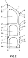
- the support wall part shown in FIG. 2, which otherwise corresponds to the support wall parts of FIG. 1, does not have this grating.
- the reference numeral 4 in FIGS. 1 and 2 denotes an upper edge of the support wall parts, which is chamfered in the present case.
- the beveled edges serve to accommodate roof parts 5 which are inclined in accordance with the beveled edges 4.
- threaded bushings 12 and 13 for a screw connection between the roof parts 5 and the support wall parts 1 are let into the support surfaces. Further threaded bushings, which can be used to connect the support wall parts 1 to a foundation in the ground, are identified in FIG. 2 by the reference number 51.
- the reference numeral 14 in FIG. 1 designates a first intermediate floor made of wood, which has four cross members 15 arranged at the same distance and parallel to one another, of which three cross members 15 are visible in FIG. 1.
- the carrier 15 provided at each end of the intermediate floor 14 rests on bearing surfaces 11 'which are provided in the concrete wall parts.
- the two cross members arranged between the cross members 15 at the ends of the intermediate floor 14 engage in recesses 16 'in the support wall parts 1, where they rest on contact surfaces 17'.
- the reference numeral 14 'in FIG. 1 denotes a further intermediate floor, which is designed in the same way as the intermediate floor 14 and rests with four cross members 15' on support surfaces 11 '' or 17 '' formed in the concrete part 1.
- the upper intermediate floor 14 ' is connected to side walls 19 and 20.
- the side walls 19 are attached at their lower edge to the cross member 15 'of the intermediate floor 14' and with their upper edge to the lower cross member 7 of the roof part 5.
- window openings 21 are provided in the wooden side walls 19
- the side walls 20, which also consist of wood in the present exemplary embodiment, are connected at their lower edge to the intermediate floor 14 '. Connections can be made between the side edges of the walls 20 and the adjacent concrete parts for further stabilization.
- the intermediate floor 14 ' has an opening (not visible in FIG. 1) through which the intermediate floor 14' can be reached via the intermediate floor 14.
- 22 in Fig. 1 is a rise to the intermediate floor 14, which is provided with transverse, preventing slipping strips 23.
- 24 denotes a slide from the intermediate floor 14 and reference numeral 24 'denotes a slide which starts from the intermediate floor 14', the latter being adjacent to the intermediate floor 14 'opposite the side wall 20.
- the wooden parts that are subject to greater wear can be easily replaced, and a renewal of the play building shown in FIG. 1 can generally be limited to an exchange of these parts.
- the very resistant stationary concrete parts are subject to much less wear, so that their service life far exceeds that of the easily replaceable wooden parts.
- the use of concrete as a material for the stationary parts anchored in the ground has the further advantage that this material can be designed in any manner by means of casting molds. In addition to a low production energy consumption in production dispose of this material easily. No preservatives are required to preserve it, which is harmful to the environment when it is disposed of. The dimensional stability and static strength are guaranteed over the entire service life.
- FIG. 1 While in Fig. 1 two pairs of parallel spaced support wall parts are arranged symmetrically with respect to an axis extending to the longitudinal sides of the roof parts 5, in Fig. 3 such concrete parts are arranged in a cross shape such that the extensions of their inclined upper edges 4 in converge at a point.
- the reference numerals 5a indicate four roof parts, which in the type of a hip roof are joined, the roof parts abutting each other above the inclined upper edges 4 of the support wall parts 1 and are supported at the joints by the upper edge 4 of the support wall parts.
- the support wall parts made of concrete also anchored in the ground in the embodiment shown in FIG spaced that the abutting roof parts 5a form a central opening 26.
- 14a and 14a ' denote intermediate floors which, like the intermediate floors 14 and 14' of the play building of FIG. 1, each have cross-member parts on support surfaces 11 'and 11''and17' and 17 '' of the concrete parts. Accordingly, the bearing surfaces 11 and 12 of the concrete parts 1 are used to remove the roof parts.
- the intermediate floors 14a and 14a ' have approximately identical central openings 26' and 26 '' with respect to a vertical axis to the opening 26.
- the game building shown in FIG. 3 could be further expanded, for example, by slipping and ladder steps created on the intermediate floors.
- a renewal can also be limited to the easily replaceable wooden parts in the game building according to FIG. 3.
- support wall parts according to FIG. 2 are arranged in a row at a predetermined grid spacing, the upper inclined edges of the support wall parts each being inclined in the same direction. 4, the same parts with the same and equivalent parts with the same, but provided with the index b reference number as in Fig. 1 are designated.
- wooden roof parts 5 are provided as in FIG. 1, the length of which corresponds to the grid length, and which collide over the sloping upper edges of the support wall parts 1.
- the roof parts 5 are supported on the concrete parts via cross beams in the same way as the roof parts 5 of FIG. 1.
- the roof parts 5 having the grid length are standard components like the concrete parts 1.
- corresponding standard roof parts 5 can be used both in the game building of FIG. 1 and that of FIG. 4.
- a first and a second intermediate floor are designated by 14b and 14b ', each of which also has the grid length and which in the same way as the intermediate floors 14 and 14' of the game building of FIG. 1 on support surfaces 11 ', 11 '', 17 'and 17''of the concrete wall parts 1 are held.
- Intermediate floors of adjoining grid sections of the game building of FIG. 4 abutting in the same plane lie with support ends approximately on one half of these support surfaces provided in the concrete parts.
- the intermediate floors 14b and 14b ' are versatile standard parts in that, like the roof parts 5, they have standard dimensions in terms of length and width, the length of the intermediate floors corresponding to the grid dimension.
- the intermediate floors in the exemplary embodiment shown in FIG. 4, like the roof parts 5, are wooden parts.
- the reference symbols 27, 28 and 29 in FIG. 4 designate wooden side walls with window openings, a transverse wall 31 extending over part of the width of the intermediate floor adjoining the side wall 23 between an intermediate floor 14b and an intermediate floor 14b '.
- the reference number 30 in FIG. 4 denotes grid parts arranged between the side wall parts 27 and 28.
- Both the side wall parts 27 and 28 and the grid parts could, for example, be provided as standardized standard parts, which could be attached at any points of the game building formed by a number of grid sections.
- the side wall 29 with the transverse wall 31 connected to it could be such a standard part that can be installed at various locations in the game building.
- the reference number 35 in FIG. 4 is in each case a grid spacing extending rear wall parts called.
- the rear wall parts are designed as sound insulation walls.
- the sound-absorbing rear wall parts designed in the present exemplary embodiment as easily replaceable components could also be provided as stationary components.
- FIG. 5 in which the same parts are designated with the same reference number as in FIG. 4, further possible variations of the game building shown in FIG. 4 emerge.
- the game building shown in FIG. 5 differs in the grid sections shown from the game building according to FIG. 4 in that slides 32 and 33 are provided instead of the side walls 27, 28 and 29.
- 34 in FIG. 7 denotes a grating which is laterally offset in comparison to the grating 30 of FIG. 4.
- the game building shown in FIG. 5, like the game building according to FIG. 4, has rear walls 35 which are designed as sound-absorbing walls and, as standard parts, have a width corresponding to the grid dimension.
- the exemplary embodiment shown in FIG. 6 for a game building like the game buildings according to FIGS. 4 and 5, has support wall parts 1 arranged in a row at a grid spacing, the grid sections of the game building adjoining a rear wall 35 'essentially having grid sections according to FIG 4 and 5 correspond.
- the rear wall 35 ' is also designed as a sound-absorbing wall and has a grid dimension Spread out.
- Climbing ropes 36 which can be provided with a plastic sheath, extend between the mutually facing support wall parts 1 of the adjacent grid sections and extend across the width of the rear wall.
- the soundproofing wall 35 ' was designed higher than the soundproofing walls 35 closing the neighboring grid sections of the play building to the rear in order to ensure adequate soundproofing also in the climbing area.
- the sound-absorbing walls 35 and 35 'of the game building shown in FIGS. 4 to 6 can be designed both as solid stationary components, for example anchored in the floor, and / or as easily replaceable components having rotting materials.
- the climbing ropes 36 used in the play building of FIG. 6 are fastened in the present exemplary embodiment to end faces of the cross members for the roof parts 5 and for the intermediate floors 14b and 14b '.
- FIG. 7 shows a section of a game building in which grid sections, as shown in FIGS. 4 to 6, are at right angles to one another, with wall support parts 1 perpendicular to one another via a roof part 36 and intermediate floors 37 and 37 'with one another are connected.
- This corner area between the mutually perpendicular support wall parts 1, like the adjacent grid sections, is closed off at the rear by a sound-absorbing rear wall 39.
- the standard parts 36 can be used for the roof parts 5a of the game building of FIG. 3 and accordingly be put together.
- the intermediate floors 14a and 14a 'of the game building of FIG. 3 can be assembled from standard parts 37 and 37', respectively.
- the intermediate floors 14 and 14 'of the game building shown in FIG. 1 could each be composed of four standard parts 5b, as are used for the intermediate floors of the game buildings shown in FIGS. 2 to 7.
- all of the game buildings shown in FIGS. 1 and 2 to 7 could be produced from a kit which contains, as standard parts, the concrete support wall parts 1, the roof parts 5 and 36, the rear wall parts 35, 35 'and 39, and the intermediate floor parts 5b and 37.
- the side walls shown can also be provided in the kit as multiple standard components.
- Game buildings constructed from such a kit with a sound-absorbing rear wall, as shown in FIGS. 2 to 7, have the advantage that ground preparation measures for fall protection are only required on one side of the game building and the effort required to erect the game buildings with respect to free-standing play buildings or free-standing play equipment is reduced.
- the play buildings shown in FIGS. 1 to 7 can be equipped with further play equipment such as swings, slides, hanging climbing ropes and the like in addition to the climbing ropes shown in FIG. 6.
- a common foundation platform for a plurality of stationary components for example a game building with a foundation platform supporting an inner courtyard, whereby, if small platform dimensions are provided, the foundation platform with game buildings which may have been completely built thereon can be transported as a whole and therefore temporarily if necessary on one desired position can be set up.
- the stationary standard support wall parts 1 can also advantageously only serve as support elements for swings 43, which are fastened to a crossbeam 42 which engages at both ends in the recesses 8 of the concrete support wall parts and on the support surfaces 10 rests, the beam can be connected to the support wall parts by a screw connection using the threaded bushings 12 in the concrete support wall parts. If the support wall parts 1 of the arrangement shown in FIG. 8 are set up at a grid spacing from one another, the arrangement could easily be expanded to a play building corresponding to a grid section of one of the play buildings shown in FIGS 42 with the swings 43 at another location, where two support wall parts are arranged at a grid spacing from one another, if this appears desirable in the context of the redesign of the playground.
- a playground could also be provided on a continuous soundproof wall in such a way that the soundproof wall also included play equipment arranged on one side of the soundproof wall is connected.
- These game facilities can include both play structures and play equipment.
- Such a playground which extends along a soundproof wall, requires only a very small piece of land, so that very narrow area strips, for example located on busy traffic routes, can be used accordingly.
- measures for soil preparation through which fall injuries are to be largely avoided, only have to be carried out on one side of the recordable soundproofing wall.
- the soundproofing wall can have a foot part which extends to form an L-shape essentially on the side of the soundproofing wall on which the game devices are arranged.
- the foot part can be connected in one piece to the soundproof wall, for example having concrete, and accordingly can itself be designed as a concrete part.
- a soundproofing wall can be constructed from corresponding L-shaped, transportable components, which can already be completely equipped with play equipment.
- the soundproofing wall can advantageously have connecting devices, such as recessed threaded bushings, for connection to components for erecting play structures and / or to play equipment. Carrier parts that serve to hold such components or / and play equipment could also be embedded in a soundproofing wall made of concrete.
- the soundproofing wall can advantageously have a surface suitable for mounting posters on the side facing away from the game devices.
- the exemplary embodiment shown in FIG. 9 for a game building is produced from a kit which has concrete parts 1a as stationary standard components, which essentially comprise halves of the wall of a round tower.
- the wall halves provided with windows 42 and embrasures 43 have an external design reminiscent of a castle tower.
- the concrete parts 1a of the play building shown in FIG. 9 are also firmly anchored in the ground. Due to their semicircular cross-section, the concrete parts also have a certain inherent stability, which may make anchoring in the floor superfluous if the surface is solid. In the case of wall corner parts, which would also be usable in a kit according to the invention, such an autonomy would also be present.
- the concrete parts 1a have two intermediate walls 44 and 44 'which extend perpendicular to the longitudinal axis and which are integrally connected to the rest of the concrete part.
- 45 and 45 ' denote intermediate floors made of wood, which, not visible in FIG. 9, are held by the intermediate walls 44 and 44' of the concrete parts 1a.
- the correspondingly formed intermediate floors 45 and 45 ' are provided at their ends with protruding parts which engage in corresponding recesses in the intermediate walls 44 and 44', respectively, where they are connected in the manner shown in FIG the concrete parts include embedded threaded bushings, can be attached.
- FIG. 10 In the example of a game building shown in FIG. 10, four tower concrete parts 1 a are used to hold two congruent platforms 47 and 47 ′ arranged one above the other.
- the platforms made of wood and easily exchangeable are provided in the same way as the intermediate floors 45 and 45 'of the game building shown in FIG. 9 with projecting parts 48 and 48' which engage in corresponding recesses in the intermediate floors 44 and 44 ' and can also be fastened there by screw connections.
- the kit on which the game buildings according to FIGS. 9 and 10 are based also allows game buildings to be constructed in various forms.
- tower halves 1a set up at a greater distance from one another could also be connected to one another by bridges or web-shaped intermediate floors, bridge connections to different tower parts being able to be produced, for example, from the intermediate walls 44 and 44 '.
Applications Claiming Priority (2)
| Application Number | Priority Date | Filing Date | Title |
|---|---|---|---|
| DE19914132321 DE4132321A1 (de) | 1991-09-27 | 1991-09-27 | Bausatz fuer kinderspielplaetze zum errichten von spielbauten |
| DE4132321 | 1991-09-27 |
Publications (1)
| Publication Number | Publication Date |
|---|---|
| EP0534058A1 true EP0534058A1 (fr) | 1993-03-31 |
Family
ID=6441689
Family Applications (1)
| Application Number | Title | Priority Date | Filing Date |
|---|---|---|---|
| EP92109313A Ceased EP0534058A1 (fr) | 1991-09-27 | 1992-06-02 | Ensemble d'éléments pour la construction d'aménagements de terrains de jeux |
Country Status (2)
| Country | Link |
|---|---|
| EP (1) | EP0534058A1 (fr) |
| DE (1) | DE4132321A1 (fr) |
Cited By (5)
| Publication number | Priority date | Publication date | Assignee | Title |
|---|---|---|---|---|
| US5496232A (en) * | 1994-10-31 | 1996-03-05 | Morris; Denny W. | Modular playground equipment system |
| USD377203S (en) | 1995-07-03 | 1997-01-07 | The Little Tikes Company | Climb and slide structure |
| USD418895S (en) | 1998-08-07 | 2000-01-11 | The Little Tikes Company | Climb and slide apparatus |
| US10155128B1 (en) | 2018-05-01 | 2018-12-18 | Maria Sophia Lefevre | Shed and modular playset accessory system |
| DE202022102271U1 (de) | 2022-04-27 | 2023-08-08 | Eiden & Wagner Metallbau Gmbh | Parkourpark |
Families Citing this family (2)
| Publication number | Priority date | Publication date | Assignee | Title |
|---|---|---|---|---|
| DE10321696A1 (de) * | 2003-05-14 | 2004-12-02 | Maurer Söhne Gmbh & Co. Kg | Modulbahn mit erhöhtem Bahnhof |
| DE102020110219A1 (de) | 2020-04-14 | 2021-10-14 | Mack Rides Gmbh & Co Kg | Fahrgeschäft |
Citations (3)
| Publication number | Priority date | Publication date | Assignee | Title |
|---|---|---|---|---|
| FR2191916A1 (fr) * | 1972-07-07 | 1974-02-08 | Gewerk Keramchemie | |
| AU595475B3 (en) * | 1982-03-04 | 1990-03-29 | Glenwood Systems Pty Ltd | Clamping ring for play structure |
| EP0462039A1 (fr) * | 1990-06-11 | 1991-12-18 | Husson Collectivites, S.A. | Dispositif de jeu modulaire |
-
1991
- 1991-09-27 DE DE19914132321 patent/DE4132321A1/de not_active Ceased
-
1992
- 1992-06-02 EP EP92109313A patent/EP0534058A1/fr not_active Ceased
Patent Citations (3)
| Publication number | Priority date | Publication date | Assignee | Title |
|---|---|---|---|---|
| FR2191916A1 (fr) * | 1972-07-07 | 1974-02-08 | Gewerk Keramchemie | |
| AU595475B3 (en) * | 1982-03-04 | 1990-03-29 | Glenwood Systems Pty Ltd | Clamping ring for play structure |
| EP0462039A1 (fr) * | 1990-06-11 | 1991-12-18 | Husson Collectivites, S.A. | Dispositif de jeu modulaire |
Cited By (5)
| Publication number | Priority date | Publication date | Assignee | Title |
|---|---|---|---|---|
| US5496232A (en) * | 1994-10-31 | 1996-03-05 | Morris; Denny W. | Modular playground equipment system |
| USD377203S (en) | 1995-07-03 | 1997-01-07 | The Little Tikes Company | Climb and slide structure |
| USD418895S (en) | 1998-08-07 | 2000-01-11 | The Little Tikes Company | Climb and slide apparatus |
| US10155128B1 (en) | 2018-05-01 | 2018-12-18 | Maria Sophia Lefevre | Shed and modular playset accessory system |
| DE202022102271U1 (de) | 2022-04-27 | 2023-08-08 | Eiden & Wagner Metallbau Gmbh | Parkourpark |
Also Published As
| Publication number | Publication date |
|---|---|
| DE4132321A1 (de) | 1993-04-01 |
Similar Documents
| Publication | Publication Date | Title |
|---|---|---|
| DE2908818A1 (de) | Abbaubare barriere | |
| EP0016353A1 (fr) | Ensemble d'éléments de construction pour ériger des structures tridimensionnelles | |
| EP0378725B1 (fr) | Piste pour planche à roulettes fabriquée à partir d'éléments uniques | |
| EP0534058A1 (fr) | Ensemble d'éléments pour la construction d'aménagements de terrains de jeux | |
| EP3428343B1 (fr) | Cache de vision destiné à la protection contre les accidents et pied pour ce cache de vision | |
| CH651095A5 (de) | Bewehrungselement zur uebertragung von querkraeften in plattenartigen traggliedern, z.b. flachdecken. | |
| DE2532520B2 (de) | Schutzvorrichtung, insbesondere schallschutzeinrichtung und boeschungsbefestigung fuer strassen, bestehend aus vorgefertigten bauteilen aus kunststein, beton o.dgl. | |
| DE2644453A1 (de) | Aus fertigteilen zusammensetzbare tragplatte | |
| CH676260A5 (en) | Noise insulating wall for side of road or railway | |
| DE2755389A1 (de) | Laermschutzwandelemente | |
| DE3111982A1 (de) | Spielflaeche mit zumindest einem kinderspielgeraet | |
| DE2657614A1 (de) | Raumkonstruktion zur bildung von bauwerken mit einer oder mehreren etagen | |
| DE3416482A1 (de) | Zerlegbarer ueberdachter gehsteig | |
| DE4315286A1 (de) | Vorgefertigtes Ankerelement, insbesondere für passive Schutzeinrichtungen | |
| EP0631022A2 (fr) | Elément tridimensionnel pour la construction d'ouvrages et procédé pour sa fabrication | |
| DE4237325C2 (de) | Raumzellenanordnung, insbesondere mobiles Gebäude in mehrgeschossiger Bauweise | |
| DE3203980C2 (de) | Unterführungsbauwerk sowie Verfahren zu seiner Herstellung | |
| DE102020123285A1 (de) | Treppenstufenbetonfertigteil | |
| EP0093453A1 (fr) | Elément de remblais | |
| DE2535826C3 (de) | Bauelement fur einen dem Schutz von Personen im Bereich von Baustellen dienenden Fußgängertunnel | |
| DE1759805B1 (de) | Aus Einzelteilen zusammensetzbare und wieder auseinandernehmbare Park- und Abstellflaeche | |
| DE2333257A1 (de) | Obere deckkonstruktion fuer kuehltuerme | |
| AT410285B (de) | Kinder-spielhaus | |
| AT393401B (de) | Garage | |
| EP0732307A2 (fr) | Pont en béton armé pour un bassin ou une fosse de traitement d'eau usée |
Legal Events
| Date | Code | Title | Description |
|---|---|---|---|
| PUAI | Public reference made under article 153(3) epc to a published international application that has entered the european phase |
Free format text: ORIGINAL CODE: 0009012 |
|
| AK | Designated contracting states |
Kind code of ref document: A1 Designated state(s): AT BE CH DE DK ES FR GB GR IT LI LU MC NL PT SE |
|
| 17P | Request for examination filed |
Effective date: 19930628 |
|
| 17Q | First examination report despatched |
Effective date: 19941121 |
|
| GRAG | Despatch of communication of intention to grant |
Free format text: ORIGINAL CODE: EPIDOS AGRA |
|
| STAA | Information on the status of an ep patent application or granted ep patent |
Free format text: STATUS: THE APPLICATION HAS BEEN REFUSED |
|
| 18R | Application refused |
Effective date: 19970929 |