EP0534058A1 - Structural assembly for playgrounds - Google Patents
Structural assembly for playgrounds Download PDFInfo
- Publication number
- EP0534058A1 EP0534058A1 EP92109313A EP92109313A EP0534058A1 EP 0534058 A1 EP0534058 A1 EP 0534058A1 EP 92109313 A EP92109313 A EP 92109313A EP 92109313 A EP92109313 A EP 92109313A EP 0534058 A1 EP0534058 A1 EP 0534058A1
- Authority
- EP
- European Patent Office
- Prior art keywords
- components
- kit according
- stationary
- wall
- parts
- Prior art date
- Legal status (The legal status is an assumption and is not a legal conclusion. Google has not performed a legal analysis and makes no representation as to the accuracy of the status listed.)
- Ceased
Links
Images


Classifications
-
- A—HUMAN NECESSITIES
- A63—SPORTS; GAMES; AMUSEMENTS
- A63B—APPARATUS FOR PHYSICAL TRAINING, GYMNASTICS, SWIMMING, CLIMBING, OR FENCING; BALL GAMES; TRAINING EQUIPMENT
- A63B9/00—Climbing poles, frames, or stages
-
- A—HUMAN NECESSITIES
- A63—SPORTS; GAMES; AMUSEMENTS
- A63B—APPARATUS FOR PHYSICAL TRAINING, GYMNASTICS, SWIMMING, CLIMBING, OR FENCING; BALL GAMES; TRAINING EQUIPMENT
- A63B9/00—Climbing poles, frames, or stages
- A63B2009/004—Three-dimensional rope or cable networks
-
- A—HUMAN NECESSITIES
- A63—SPORTS; GAMES; AMUSEMENTS
- A63B—APPARATUS FOR PHYSICAL TRAINING, GYMNASTICS, SWIMMING, CLIMBING, OR FENCING; BALL GAMES; TRAINING EQUIPMENT
- A63B2208/00—Characteristics or parameters related to the user or player
- A63B2208/12—Characteristics or parameters related to the user or player specially adapted for children
Definitions
- the invention relates to a kit for children's playgrounds for erecting play structures.
- Play structures on children's playgrounds such as small huts, castles, towers and the like are subject to heavy wear and tear by the children playing. Since wood, which can rot, is used in particular as a suitable, touch-friendly material for erecting such play structures, weather influences also have a disadvantageous effect on the lifespan of such play structures. Sometimes wanton destruction also contributes to the fact that play structures in children's playgrounds have to be replaced relatively often.
- the present invention provides a kit for erecting play structures on children's playgrounds, which makes it possible to significantly reduce the effort required to renew the play structures.
- the kit according to the invention is characterized by stationary, installable components to form a basic structure and easily replaceable components to expand the basic structure.
- the effort for renewing the play structures erected using such a kit can be substantially reduced in that only the easily replaceable components need to be replaced for renewal.
- the easily exchangeable components are preferably wooden components, which takes into account the requirement to use suitable, touch-friendly materials for play structures.
- suitable, touch-friendly materials for play structures For the stationary components, however, resistant, weatherproof material can be selected.
- the stationary components are therefore preferably made of concrete.
- the basic structure can be expanded to form different building variants by means of easily replaceable components.
- a renewal of the playground structures can be combined with a change in the playground structures, which may be perceived as a welcome change by the children using the playground structures.
- the stationary components comprise standard components of the same shape.
- Standard components of this type which can be used in a grid in a different arrangement, can be produced rationally, which further reduces the outlay for producing a kit for erecting play structures.
- the stationary and / or easily replaceable components can advantageously comprise components for forming sound-absorbing walls.
- soundproof walls can be formed at least partially surrounding the playground, which on the one hand the residents of such playgrounds against the noise of children and on the other hand the children protect against possible street noise.
- Such sound-absorbing walls help to improve the playground atmosphere, particularly on playgrounds located near busy streets.
- the soundproofing walls can also advantageously be used to shield the playground from wind. By not only shielding the playground against the ingress of sound through the sound-absorbing walls, but also, conversely, only dampening the playground noise, such play structures combined with sound-absorbing walls are particularly suitable for children's playgrounds that are located in densely built-up residential areas.
- Fig. 1 four standard support wall parts are designated by the reference numeral 1. These components, which have the same shape, are made of concrete in the present exemplary embodiment and are anchored in the ground. Instead of such ground anchoring, a weight anchoring could also be provided, for example by providing the support wall parts with solid concrete feet.
- the standard carrier wall parts 1 have window openings 2, three window openings being provided one above the other in the present exemplary embodiment.
- the uppermost window opening of the standard support wall parts is provided with a grating 3.
- This grating can be formed by steel bars, which are cast into the concrete during the manufacture of the support wall parts 1.
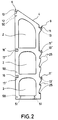
- the support wall part shown in FIG. 2, which otherwise corresponds to the support wall parts of FIG. 1, does not have this grating.
- the reference numeral 4 in FIGS. 1 and 2 denotes an upper edge of the support wall parts, which is chamfered in the present case.
- the beveled edges serve to accommodate roof parts 5 which are inclined in accordance with the beveled edges 4.
- threaded bushings 12 and 13 for a screw connection between the roof parts 5 and the support wall parts 1 are let into the support surfaces. Further threaded bushings, which can be used to connect the support wall parts 1 to a foundation in the ground, are identified in FIG. 2 by the reference number 51.
- the reference numeral 14 in FIG. 1 designates a first intermediate floor made of wood, which has four cross members 15 arranged at the same distance and parallel to one another, of which three cross members 15 are visible in FIG. 1.
- the carrier 15 provided at each end of the intermediate floor 14 rests on bearing surfaces 11 'which are provided in the concrete wall parts.
- the two cross members arranged between the cross members 15 at the ends of the intermediate floor 14 engage in recesses 16 'in the support wall parts 1, where they rest on contact surfaces 17'.
- the reference numeral 14 'in FIG. 1 denotes a further intermediate floor, which is designed in the same way as the intermediate floor 14 and rests with four cross members 15' on support surfaces 11 '' or 17 '' formed in the concrete part 1.
- the upper intermediate floor 14 ' is connected to side walls 19 and 20.
- the side walls 19 are attached at their lower edge to the cross member 15 'of the intermediate floor 14' and with their upper edge to the lower cross member 7 of the roof part 5.
- window openings 21 are provided in the wooden side walls 19
- the side walls 20, which also consist of wood in the present exemplary embodiment, are connected at their lower edge to the intermediate floor 14 '. Connections can be made between the side edges of the walls 20 and the adjacent concrete parts for further stabilization.
- the intermediate floor 14 ' has an opening (not visible in FIG. 1) through which the intermediate floor 14' can be reached via the intermediate floor 14.
- 22 in Fig. 1 is a rise to the intermediate floor 14, which is provided with transverse, preventing slipping strips 23.
- 24 denotes a slide from the intermediate floor 14 and reference numeral 24 'denotes a slide which starts from the intermediate floor 14', the latter being adjacent to the intermediate floor 14 'opposite the side wall 20.
- the wooden parts that are subject to greater wear can be easily replaced, and a renewal of the play building shown in FIG. 1 can generally be limited to an exchange of these parts.
- the very resistant stationary concrete parts are subject to much less wear, so that their service life far exceeds that of the easily replaceable wooden parts.
- the use of concrete as a material for the stationary parts anchored in the ground has the further advantage that this material can be designed in any manner by means of casting molds. In addition to a low production energy consumption in production dispose of this material easily. No preservatives are required to preserve it, which is harmful to the environment when it is disposed of. The dimensional stability and static strength are guaranteed over the entire service life.
- FIG. 1 While in Fig. 1 two pairs of parallel spaced support wall parts are arranged symmetrically with respect to an axis extending to the longitudinal sides of the roof parts 5, in Fig. 3 such concrete parts are arranged in a cross shape such that the extensions of their inclined upper edges 4 in converge at a point.
- the reference numerals 5a indicate four roof parts, which in the type of a hip roof are joined, the roof parts abutting each other above the inclined upper edges 4 of the support wall parts 1 and are supported at the joints by the upper edge 4 of the support wall parts.
- the support wall parts made of concrete also anchored in the ground in the embodiment shown in FIG spaced that the abutting roof parts 5a form a central opening 26.
- 14a and 14a ' denote intermediate floors which, like the intermediate floors 14 and 14' of the play building of FIG. 1, each have cross-member parts on support surfaces 11 'and 11''and17' and 17 '' of the concrete parts. Accordingly, the bearing surfaces 11 and 12 of the concrete parts 1 are used to remove the roof parts.
- the intermediate floors 14a and 14a ' have approximately identical central openings 26' and 26 '' with respect to a vertical axis to the opening 26.
- the game building shown in FIG. 3 could be further expanded, for example, by slipping and ladder steps created on the intermediate floors.
- a renewal can also be limited to the easily replaceable wooden parts in the game building according to FIG. 3.
- support wall parts according to FIG. 2 are arranged in a row at a predetermined grid spacing, the upper inclined edges of the support wall parts each being inclined in the same direction. 4, the same parts with the same and equivalent parts with the same, but provided with the index b reference number as in Fig. 1 are designated.
- wooden roof parts 5 are provided as in FIG. 1, the length of which corresponds to the grid length, and which collide over the sloping upper edges of the support wall parts 1.
- the roof parts 5 are supported on the concrete parts via cross beams in the same way as the roof parts 5 of FIG. 1.
- the roof parts 5 having the grid length are standard components like the concrete parts 1.
- corresponding standard roof parts 5 can be used both in the game building of FIG. 1 and that of FIG. 4.
- a first and a second intermediate floor are designated by 14b and 14b ', each of which also has the grid length and which in the same way as the intermediate floors 14 and 14' of the game building of FIG. 1 on support surfaces 11 ', 11 '', 17 'and 17''of the concrete wall parts 1 are held.
- Intermediate floors of adjoining grid sections of the game building of FIG. 4 abutting in the same plane lie with support ends approximately on one half of these support surfaces provided in the concrete parts.
- the intermediate floors 14b and 14b ' are versatile standard parts in that, like the roof parts 5, they have standard dimensions in terms of length and width, the length of the intermediate floors corresponding to the grid dimension.
- the intermediate floors in the exemplary embodiment shown in FIG. 4, like the roof parts 5, are wooden parts.
- the reference symbols 27, 28 and 29 in FIG. 4 designate wooden side walls with window openings, a transverse wall 31 extending over part of the width of the intermediate floor adjoining the side wall 23 between an intermediate floor 14b and an intermediate floor 14b '.
- the reference number 30 in FIG. 4 denotes grid parts arranged between the side wall parts 27 and 28.
- Both the side wall parts 27 and 28 and the grid parts could, for example, be provided as standardized standard parts, which could be attached at any points of the game building formed by a number of grid sections.
- the side wall 29 with the transverse wall 31 connected to it could be such a standard part that can be installed at various locations in the game building.
- the reference number 35 in FIG. 4 is in each case a grid spacing extending rear wall parts called.
- the rear wall parts are designed as sound insulation walls.
- the sound-absorbing rear wall parts designed in the present exemplary embodiment as easily replaceable components could also be provided as stationary components.
- FIG. 5 in which the same parts are designated with the same reference number as in FIG. 4, further possible variations of the game building shown in FIG. 4 emerge.
- the game building shown in FIG. 5 differs in the grid sections shown from the game building according to FIG. 4 in that slides 32 and 33 are provided instead of the side walls 27, 28 and 29.
- 34 in FIG. 7 denotes a grating which is laterally offset in comparison to the grating 30 of FIG. 4.
- the game building shown in FIG. 5, like the game building according to FIG. 4, has rear walls 35 which are designed as sound-absorbing walls and, as standard parts, have a width corresponding to the grid dimension.
- the exemplary embodiment shown in FIG. 6 for a game building like the game buildings according to FIGS. 4 and 5, has support wall parts 1 arranged in a row at a grid spacing, the grid sections of the game building adjoining a rear wall 35 'essentially having grid sections according to FIG 4 and 5 correspond.
- the rear wall 35 ' is also designed as a sound-absorbing wall and has a grid dimension Spread out.
- Climbing ropes 36 which can be provided with a plastic sheath, extend between the mutually facing support wall parts 1 of the adjacent grid sections and extend across the width of the rear wall.
- the soundproofing wall 35 ' was designed higher than the soundproofing walls 35 closing the neighboring grid sections of the play building to the rear in order to ensure adequate soundproofing also in the climbing area.
- the sound-absorbing walls 35 and 35 'of the game building shown in FIGS. 4 to 6 can be designed both as solid stationary components, for example anchored in the floor, and / or as easily replaceable components having rotting materials.
- the climbing ropes 36 used in the play building of FIG. 6 are fastened in the present exemplary embodiment to end faces of the cross members for the roof parts 5 and for the intermediate floors 14b and 14b '.
- FIG. 7 shows a section of a game building in which grid sections, as shown in FIGS. 4 to 6, are at right angles to one another, with wall support parts 1 perpendicular to one another via a roof part 36 and intermediate floors 37 and 37 'with one another are connected.
- This corner area between the mutually perpendicular support wall parts 1, like the adjacent grid sections, is closed off at the rear by a sound-absorbing rear wall 39.
- the standard parts 36 can be used for the roof parts 5a of the game building of FIG. 3 and accordingly be put together.
- the intermediate floors 14a and 14a 'of the game building of FIG. 3 can be assembled from standard parts 37 and 37', respectively.
- the intermediate floors 14 and 14 'of the game building shown in FIG. 1 could each be composed of four standard parts 5b, as are used for the intermediate floors of the game buildings shown in FIGS. 2 to 7.
- all of the game buildings shown in FIGS. 1 and 2 to 7 could be produced from a kit which contains, as standard parts, the concrete support wall parts 1, the roof parts 5 and 36, the rear wall parts 35, 35 'and 39, and the intermediate floor parts 5b and 37.
- the side walls shown can also be provided in the kit as multiple standard components.
- Game buildings constructed from such a kit with a sound-absorbing rear wall, as shown in FIGS. 2 to 7, have the advantage that ground preparation measures for fall protection are only required on one side of the game building and the effort required to erect the game buildings with respect to free-standing play buildings or free-standing play equipment is reduced.
- the play buildings shown in FIGS. 1 to 7 can be equipped with further play equipment such as swings, slides, hanging climbing ropes and the like in addition to the climbing ropes shown in FIG. 6.
- a common foundation platform for a plurality of stationary components for example a game building with a foundation platform supporting an inner courtyard, whereby, if small platform dimensions are provided, the foundation platform with game buildings which may have been completely built thereon can be transported as a whole and therefore temporarily if necessary on one desired position can be set up.
- the stationary standard support wall parts 1 can also advantageously only serve as support elements for swings 43, which are fastened to a crossbeam 42 which engages at both ends in the recesses 8 of the concrete support wall parts and on the support surfaces 10 rests, the beam can be connected to the support wall parts by a screw connection using the threaded bushings 12 in the concrete support wall parts. If the support wall parts 1 of the arrangement shown in FIG. 8 are set up at a grid spacing from one another, the arrangement could easily be expanded to a play building corresponding to a grid section of one of the play buildings shown in FIGS 42 with the swings 43 at another location, where two support wall parts are arranged at a grid spacing from one another, if this appears desirable in the context of the redesign of the playground.
- a playground could also be provided on a continuous soundproof wall in such a way that the soundproof wall also included play equipment arranged on one side of the soundproof wall is connected.
- These game facilities can include both play structures and play equipment.
- Such a playground which extends along a soundproof wall, requires only a very small piece of land, so that very narrow area strips, for example located on busy traffic routes, can be used accordingly.
- measures for soil preparation through which fall injuries are to be largely avoided, only have to be carried out on one side of the recordable soundproofing wall.
- the soundproofing wall can have a foot part which extends to form an L-shape essentially on the side of the soundproofing wall on which the game devices are arranged.
- the foot part can be connected in one piece to the soundproof wall, for example having concrete, and accordingly can itself be designed as a concrete part.
- a soundproofing wall can be constructed from corresponding L-shaped, transportable components, which can already be completely equipped with play equipment.
- the soundproofing wall can advantageously have connecting devices, such as recessed threaded bushings, for connection to components for erecting play structures and / or to play equipment. Carrier parts that serve to hold such components or / and play equipment could also be embedded in a soundproofing wall made of concrete.
- the soundproofing wall can advantageously have a surface suitable for mounting posters on the side facing away from the game devices.
- the exemplary embodiment shown in FIG. 9 for a game building is produced from a kit which has concrete parts 1a as stationary standard components, which essentially comprise halves of the wall of a round tower.
- the wall halves provided with windows 42 and embrasures 43 have an external design reminiscent of a castle tower.
- the concrete parts 1a of the play building shown in FIG. 9 are also firmly anchored in the ground. Due to their semicircular cross-section, the concrete parts also have a certain inherent stability, which may make anchoring in the floor superfluous if the surface is solid. In the case of wall corner parts, which would also be usable in a kit according to the invention, such an autonomy would also be present.
- the concrete parts 1a have two intermediate walls 44 and 44 'which extend perpendicular to the longitudinal axis and which are integrally connected to the rest of the concrete part.
- 45 and 45 ' denote intermediate floors made of wood, which, not visible in FIG. 9, are held by the intermediate walls 44 and 44' of the concrete parts 1a.
- the correspondingly formed intermediate floors 45 and 45 ' are provided at their ends with protruding parts which engage in corresponding recesses in the intermediate walls 44 and 44', respectively, where they are connected in the manner shown in FIG the concrete parts include embedded threaded bushings, can be attached.
- FIG. 10 In the example of a game building shown in FIG. 10, four tower concrete parts 1 a are used to hold two congruent platforms 47 and 47 ′ arranged one above the other.
- the platforms made of wood and easily exchangeable are provided in the same way as the intermediate floors 45 and 45 'of the game building shown in FIG. 9 with projecting parts 48 and 48' which engage in corresponding recesses in the intermediate floors 44 and 44 ' and can also be fastened there by screw connections.
- the kit on which the game buildings according to FIGS. 9 and 10 are based also allows game buildings to be constructed in various forms.
- tower halves 1a set up at a greater distance from one another could also be connected to one another by bridges or web-shaped intermediate floors, bridge connections to different tower parts being able to be produced, for example, from the intermediate walls 44 and 44 '.
Abstract
Description
Die Erfindung betrifft einen Bausatz für Kinderspielplätze zum Errichten von Spielbauten.The invention relates to a kit for children's playgrounds for erecting play structures.
Spielbauten auf Kinderspielplätzen, wie kleine Hütten, Burgen, Türme und ähnliches unterliegen einer starken Beanspruchung und Abnutzung durch die spielenden Kinder. Da zur Errichtung solcher Spielbauten als geeignetes, berührungsfreundliches Material insbesondere Holz verwendet wird, das verrotten kann, wirken sich auch Witterungseinflüsse nachteilig auf die Lebensdauer solcher Spielbauten aus. Mitunter tragen auch mutwillige Zerstörungen dazu bei, daß Spielbauten auf Kinderspielplätzen verhältnismäßig oft erneuert werden müssen.Play structures on children's playgrounds such as small huts, castles, towers and the like are subject to heavy wear and tear by the children playing. Since wood, which can rot, is used in particular as a suitable, touch-friendly material for erecting such play structures, weather influences also have a disadvantageous effect on the lifespan of such play structures. Sometimes wanton destruction also contributes to the fact that play structures in children's playgrounds have to be replaced relatively often.
Durch die vorliegende Erfindung wird ein Bausatz zur Errichtung von Spielbauten auf Kinderspielplätzen geschaffen, der es ermöglicht, den Aufwand zur Erneuerung der Spielbauten erheblich zu verringern.The present invention provides a kit for erecting play structures on children's playgrounds, which makes it possible to significantly reduce the effort required to renew the play structures.
Der erfindungsgemäße Bausatz ist durch stationäre, installierbare Bauelemente zur Bildung eines Grundaufbaus und leicht auswechselbare Bauelemente zum Ausbau des Grundaufbaus gekennzeichnet.The kit according to the invention is characterized by stationary, installable components to form a basic structure and easily replaceable components to expand the basic structure.
Durch diese erfindungsgemäße Lösung läßt sich der Aufwand zum Erneuern der unter Verwendung eines solchen Bausatzes errichteten Spielbauten dadurch wesentlich verringern, daß zur Erneuerung nur die leicht auswechselbaren Bauelemente ersetzt zu werden brauchen.With this solution according to the invention, the effort for renewing the play structures erected using such a kit can be substantially reduced in that only the easily replaceable components need to be replaced for renewal.
Vorzugsweise handelt es sich bei den leicht auswechselbaren Bauelementen um Holzbauteile, womit der Forderung, für Spielbauten geeignete, berührungsfreundliche Materialien zu verwenden, Rechnung getragen wird. Für die stationären Bauelemente kann dagegen widerstandsfähiges, witterungsbeständiges Material ausgewählt werden. Vorzugsweise bestehen die stationären Bauelemente daher aus Beton.The easily exchangeable components are preferably wooden components, which takes into account the requirement to use suitable, touch-friendly materials for play structures. For the stationary components, however, resistant, weatherproof material can be selected. The stationary components are therefore preferably made of concrete.
In weiterer vorteilhafter Ausgestaltung der Erfindung kann vorgesehen sein, daß der Grundaufbau durch leicht auswechselbare Bauelemente zu verschiedenen Bautenvarianten ausbaubar ist. Damit läßt sich eine Erneuerung der Spielplatzbauten gleichzeitig mit einer Veränderung der Spielbauten verbinden, was von den die Spielbauten benutzenden Kindern möglicherweise als willkommene Abswechselung empfunden wird.In a further advantageous embodiment of the invention, it can be provided that the basic structure can be expanded to form different building variants by means of easily replaceable components. In this way, a renewal of the playground structures can be combined with a change in the playground structures, which may be perceived as a welcome change by the children using the playground structures.
In weiterer vorteilhafter Ausgestaltung der Erfindung kann vorgesehen sein, daß die stationären Bauelemente formgleiche Standardbauteile umfassen. Solche Standardbauteile, die in einem Raster in unterschiedlicher Anordnung verwendet werden können, lassen sich rationell herstellen, wodurch sich der Aufwand zur Herstellung eines Bausatzes zum Errichten von Spielbauten weiter verringert.In a further advantageous embodiment of the invention it can be provided that the stationary components comprise standard components of the same shape. Standard components of this type, which can be used in a grid in a different arrangement, can be produced rationally, which further reduces the outlay for producing a kit for erecting play structures.
Vorteilhaft können die stationären und/oder leicht auswechselbaren Bauelemente Bauteile zur Bildung von schalldämmenden Wänden umfassen. Dadurch können etwa den Spielplatz wenigstens teilweise umgebende Schallschutzwände gebildet werden, die einerseits die Anlieger von solchen Spielplätzen vor dem Kinderlärm und andererseits die Kinder vor etwaigem Straßenlärm schützen. Solche schalldämmenden Wände tragen insbesondere auf in der Nähe belebter Straßen gelegenen Spielplätzen zu einer Verbesserung der Spielplatzatmosphäre bei. Durch die schalldämmenden Wände kann auch vorteilhaft eine Abschirmung des Spielplatzes gegen Wind erfolgen. Indem durch die schalldämmenden Wände nicht nur der Spielplatz gegen eindringenden Schall abgeschirmt wird, sondern auch umgekehrt der Spielplatzlärm nur gedämpft nach außen dringt, eignen sich solche mit schalldämmenden Wänden kombinierte Spielbauten insbesondere für Kinderspielplätze, die in dicht bebauten Wohngebieten liegen. Werden derartige Schallschutzwände mit den Spieleinrichtungen kombiniert, so bedeutet dies, daß die Spieleinrichtungen nur von der der Lärmschutzwand abgelegenen Seite zugänglich sind. Das bringt den wesentlichen weiteren Vorteil mit sich, daß die Fläche des Bodens um die Spieleinrichtung herum, die für das Herunterfallen der Kinder besonders präpariert werden muß und deshalb besonders kostspielig ist, auf die Hälfte verringert werden kann.The stationary and / or easily replaceable components can advantageously comprise components for forming sound-absorbing walls. As a result, soundproof walls can be formed at least partially surrounding the playground, which on the one hand the residents of such playgrounds against the noise of children and on the other hand the children protect against possible street noise. Such sound-absorbing walls help to improve the playground atmosphere, particularly on playgrounds located near busy streets. The soundproofing walls can also advantageously be used to shield the playground from wind. By not only shielding the playground against the ingress of sound through the sound-absorbing walls, but also, conversely, only dampening the playground noise, such play structures combined with sound-absorbing walls are particularly suitable for children's playgrounds that are located in densely built-up residential areas. If such noise barriers are combined with the gaming facilities, this means that the gaming facilities are only accessible from the side remote from the noise barriers. This brings with it the further significant advantage that the area of the floor around the play facility, which has to be specially prepared for the falling of the children and is therefore particularly expensive, can be reduced by half.
Weitere vorteilhafte Ausgestaltungsmöglichkeiten der Erfindung gehen aus den Unteransprüchen hervor.Further advantageous design options of the invention emerge from the subclaims.
Die Erfindung soll nun anhand von Ausführungsbeispielen und der beiliegenden, sich auf diese Ausführungsbeispiele beziehenden Zeichnungen näher erläutert und beschrieben werden.The invention will now be explained and described in more detail with reference to exemplary embodiments and the accompanying drawings relating to these exemplary embodiments.
Es zeigen:
- Fig.1
- ein Ausführungsbeispiel für ein mit einem erfindungsgemäßen Bausatz errichtetes Spielgebäude unter Verwendung eines ersten stationären Standardträgerwandteils,
- Fig.2
- das bei dem Spielgebäude gemäß Fig. 1 verwendete Standardträgerwandteil in einer Seitenansicht,
- Fig.3
- ein weiteres Ausführungsbeispiel für ein mit einem erfindungsgemäßen Bausatz unter Verwendung des Standardbauteils von Fig. 2 errichtetes Spielgebäude,
- Fig.4
- ein drittes Ausführungsbeispiel für ein mit einem erfindungsgemäßen Bausatz unter Verwendung des Standardbauteils von Fig. 2 errichtetes Spielgebäude,
- Fig.5
- ein viertes Ausführungsbeispiel für ein mit einem erfindungsgemäßen Bausatz unter Verwendung des Standardbauteils von Fig. 2 errichtetes Spielgebäude,
- Fig.6
- ein fünftes Ausführungsbeispiel für ein mit einem erfindungsgemäßen Bausatz unter Verwendung des Standardbauteils von Fig. 2 errichtetes Spielgebäude,
- Fig.7
- ein sechstes Ausführungsbeispiel für ein mit einem erfindungsgemäßen Bausatz unter Verwendung des Standardbauteils von Fig. 2 errichtetes Spielgebäude,
- Fig.8
- ein unter Verwendung des Standardbauteils gemäß Fig. 2 errichteter Aufbau zur Halterung von Schaukeln,
- Fig.9
- ein siebentes Ausführungsbeispiel für ein mit einem erfindungsgemäßen Bausatz errichtetes Spielgebäude, wobei ein zweites Standardträgerwandteil verwendet ist, und
- Fig.10
- eine achtes Ausführungsbeispiel für ein mit einem erfindungsgemäßen Bausatz errichtetes Spielgebäude, das unter Verwendung des zweiten Standardträgerwandteils aufgebaut ist.
- Fig. 1
- 1 shows an exemplary embodiment of a game building constructed with a kit according to the invention using a first stationary standard support wall part,
- Fig. 2
- 1 in a side view, the standard support wall part used in the game building,
- Fig. 3
- 2 shows another exemplary embodiment of a game building erected with a kit according to the invention using the standard component from FIG. 2,
- Fig. 4
- 3 shows a third exemplary embodiment of a game building erected with a kit according to the invention using the standard component from FIG. 2,
- Fig. 5
- 4 shows a fourth exemplary embodiment of a game building erected with a kit according to the invention using the standard component from FIG. 2,
- Fig. 6
- 5 shows a fifth exemplary embodiment of a game building constructed with a kit according to the invention using the standard component from FIG. 2,
- Fig. 7
- 6 shows a sixth exemplary embodiment of a game building constructed with a kit according to the invention using the standard component from FIG. 2,
- Fig. 8
- a set up using the standard component according to FIG. 2 for holding swings,
- Fig. 9
- a seventh embodiment of a game building erected with a kit according to the invention, wherein a second standard support wall part is used is and
- Fig. 10
- an eighth embodiment of a game building constructed with a kit according to the invention, which is constructed using the second standard support wall part.
In der Fig. 1 sind mit dem Bezugszeichen 1 vier Standardträgerwandteile bezeichnet. Diese in ihrer Form übereinstimmenden Bauteile bestehen im vorliegenden Ausführungsbeispiel aus Beton und sind im Erdboden verankert. Statt einer solchen Erdbodenverankerung könnte auch eine Gewichtsverankerung vorgesehen sein, indem die Trägerwandteile zum Beispiel mit massiven Betonfüßen versehen werden.In Fig. 1, four standard support wall parts are designated by the
Die Standardträgerwandteile 1 weisen, wie auch aus der Fig. 2 hervorgeht, Fensterdurchbrüche 2 auf, wobei im vorliegenden Ausführungsbeispiel drei Fensterdurchbrüche übereinander vorgesehen sind. Der jeweils oberste Fensterdurchbruch der Standardträgerwandteile ist mit einer Vergitterung 3 versehen. Diese Vergitterung kann durch Stahlstangen gebildet sein, welche bei der Herstellung der Trägerwandteile 1 mit in den Beton eingegossen werden. Das in der Fig. 2 dargestellte, ansonsten den Trägerwandteilen von Fig. 1 entsprechende Trägerwandteil weist diese Vergitterung nicht auf. Mit dem Bezugszeichen 4 ist in den Fig. 1 und 2 ein oberer Rand der Trägerwandteile bezeichnet, welcher im vorliegenden Fall abgeschrägt ist. Die abgeschrägten Ränder dienen zur Aufnahme von Dachteilen 5, die entsprechend den abgeschrägten Rändern 4 geneigt sind. Die im vorliegenden Ausführungsbeispiel aus Holz bestehenden Dachteile 5 weisen obere Querträger 6 und untere Querträger 7 auf, welche in Ausnehmungen 8 bzw. 9 der Trägerwandteile eingreifen. Wie aus der Fig. 2 hervorgeht weisen die Ausnehmungen 8 und 9 horizontale Auflageflächen 10 und 11 für die Querträger auf. In die Auflageflächen sind im vorliegenden Ausführungsbeispiel Gewindebuchsen 12 bzw. 13 für eine Schraubverbindung zwischen den Dachteilen 5 und den Trägerwandteilen 1 eingelassen. Weitere Gewindebuchsen, die zur Verbindung der Trägerwandteile 1 mit einem Fundament im boden dienen können, sind in der Fig. 2 mit dem Bezugszeichen 51 bezeichnet.As is also apparent from FIG. 2, the standard
Mit dem Bezugszeichen 14 ist in der Fig. 1 ein erster Zwischenboden aus Holz bezeichnet, welcher vier im gleichen Abstand und parallel zueinander angeordnete Querträger 15 aufweist, von denen in der Fig. 1 drei Querträger 15 sichtbar sind. Der jeweils an einem Ende des Zwischenbodens 14 vorgesehene Träger 15 liegt auf Auflageflächen 11' auf, welche in den Betonwandteilen vorgesehen sind. Die beiden zwischen den Querträgern 15 an den Enden des Zwischenbodens 14 angeordneten Querträger greifen in Ausnehmungen 16' in den Trägerwandteilen 1 ein, wo sie auf Auflageflächen 17' aufliegen.The
In die Auflageflächen 11' sind wie in die Auflageflächen 11 Gewindebuchsen 13' eingelassen, wodurch der Zwischenboden an seinen vier Ecken mit den Betonteilen 1 über eine Schraubverbindung verbindbar ist. Mit dem Bezugszeichen 14' ist in der Fig. 1 ein weiterer Zwischenboden bezeichnet, der in der gleichen Weise wie der Zwischenboden 14 ausgebildet ist und mit vier Querträgern 15' auf in dem Betonteil 1 ausgebildeten Auflageflächen 11'' bzw. 17'' aufliegt. Der obere Zwischenboden 14' ist mit Seitenwänden 19 und 20 verbunden. Die Seitenwände 19 sind an ihrem unteren Rand an dem Querträger 15' des Zwischenbodens 14' und mit ihrem oberen Rand an dem unteren Querträger 7 des Dachteils 5 befestigt. In den aus Holz hergestellten Seitenwänden 19 sind Fensterdurchbrüche 21 vorgesehen. Die Seitenwände 20, die im vorliegenden Ausführungsbeispiel ebenfalls aus Holz bestehen, sind an ihrem unteren Rand mit dem Zwischenboden 14' verbunden. Zur weiteren Stabilisierung können Verbindungen zwischen den Seitenrändern der Wände 20 und den angrenzenden Betonteilen hergestellt sein. Der Zwischenboden 14' weist eine in der Fig. 1 nicht sichtbare Öffnung auf, durch die man über den Zwischenboden 14 auf den Zwischenboden 14' gelangen kann. Mit 22 ist in der Fig. 1 ein Aufgang zum Zwischenboden 14 bezeichnet, der mit querverlaufenden, ein Abrutschen verhindernden Leisten 23 versehen ist. Mit 24 ist eine vom Zwischenboden 14 und mit dem Bezugszeichen 24' eine vom Zwischenboden 14' ausgehende Rutschbahn bezeichnet, wobei letztere gegenüber der Seitenwand 20 an den Zwischenboden 14' angrenzt.As in the support surfaces 11, threaded bushings 13 'are embedded in the support surfaces 11', as a result of which the intermediate floor can be connected at its four corners to the
Spielende Kinder können das Spielgebäude über den Aufgang 22 betreten und zum Beispiel über die in der Fig. 1 nicht sichtbare Öffnung in dem Zwischenboden 14' auf den Zwischenboden 14' gelangen. Beide Zwischenböden können über die im vorliegenden Ausführungsbeispiel aus Metall bestehenden Rutschen 24 und 24' verlassen werden.Children playing can enter the play building via the
Die einem höherem Verschleiß unterliegenden Holzteile können leicht ausgewechselt werden, wobei eine Erneuerung des in der Fig. 1 gezeigten Spielgebäudes im allgemeinen auf eine Auswechselung dieser Teile beschränkt bleiben kann. Die sehr widerstandsfähigen stationären Betonteile unterliegen einem weit geringeren Verschleiß, so daß ihre Lebensdauer diejenige der leicht auswechselbaren Holzteile weit übersteigt. Die Verwendung von Beton als Material für die stationären, im Boden verankerten Teile hat weiterhin den Vorteil, daß sich dieses Material durch Gießformen in beliebiger Weise gestalten läßt. Neben einem geringen Gestehungsenergieverbrauch bei der Herstellung läßt sich dieses Material auch problemlos entsorgen. Zur Haltbarmachung werden keine, die Umwelt bei einer eventuellen Entsorgung belastenden Mittel benötigt, die Formbeständigkeit und statische Festigkeit sind über die gesamte Nutzungsdauer gewährleistet.The wooden parts that are subject to greater wear can be easily replaced, and a renewal of the play building shown in FIG. 1 can generally be limited to an exchange of these parts. The very resistant stationary concrete parts are subject to much less wear, so that their service life far exceeds that of the easily replaceable wooden parts. The use of concrete as a material for the stationary parts anchored in the ground has the further advantage that this material can be designed in any manner by means of casting molds. In addition to a low production energy consumption in production dispose of this material easily. No preservatives are required to preserve it, which is harmful to the environment when it is disposed of. The dimensional stability and static strength are guaranteed over the entire service life.
Bei der Erneuerung des in der Fig. 1 gezeigten Spielgebäudes durch Auswechseln der nicht stationären Bauteile könnten Variationen dahingehend vorgenommen werden, daß zum Beispiel Seitenwände, wie die Seitenwände 19 und 20 an anderen Stellen und mit anderen Abmessungen vorgesehen werden, oder es könnten zum Beispiel weitere an den Standardträgerwandteilen 1 vorgesehene Auflageflächen 25 für die Auflage von zusätzlichen Teilen genutzt werden. Ansonsten dienen die Auflageflächen 25 als Trittflächen, die ein Klettern vom Erdboden zum ersten Zwischenboden oder von Zwischenboden zu Zwischenboden zu ermöglichen.When the game building shown in FIG. 1 is renewed by replacing the non-stationary components, variations could be made such that side walls, such as the
Während in der Fig. 1 zwei Paare von parallel beabstandeten Trägerwandteilen symmetrisch in bezug auf eine sich zu den Längsseiten der Dachteile 5 erstreckende Achse angeordnet sind, sind in der Fig. 3 derartige Betonteile kreuzförmig derart angeordnet, daß die Verlängerungen ihrer geneigten oberen Ränder 4 in einem Punkt zusammenlaufen. In der Fig. 3, in der gleiche Teile mit der gleichen Bezugszahl und eine ähnliche Funktion ausübende Teile mit der gleichen jedoch mit dem Index a versehenen Bezugszahl wie in der Fig. 1 bezeichnet sind, weisen die Bezugszeichen 5a auf vier Dachteile hin, die in der Art eines Walmdaches zusammengefügt sind, wobei die Dachteile jeweils über den geneigten oberen Rändern 4 der Trägerwandteile 1 aneinanderstoßen und an den Stoßstellen durch den oberen Rand 4 der Trägerwandteile abgestützt sind. Die auch bei dem in der Fig. 3 gezeigten Ausführungsbeispiel im Erdboden verankerten Trägerwandteile aus Beton sind derart zueinander beabstandet, daß die aneinanderstoßenden Dachteile 5a eine Mittelöffnung 26 bilden. Mit 14a und 14a' sind in der Fig. 3 Zwischenböden bezeichnet, die wie die Zwischenböden 14 und 14' des Spielgebäudes von Fig. 1 jeweils mit Querträgerteilen auf Auflageflächen 11' und 11'' sowie 17' und 17'' der Betonteile aufliegen. Zum Abtragen der Dachteile sind dementsprechend die Auflageflächen 11 und 12 der Betonteile 1 verwendet. Die Zwischenböden 14a und 14a' weisen in bezug auf eine vertikale Achse zu der Öffnung 26 etwa deckungsgleiche Mittenöffnungen 26' und 26'' auf.While in Fig. 1 two pairs of parallel spaced support wall parts are arranged symmetrically with respect to an axis extending to the longitudinal sides of the
Das in der Fig. 3 gezeigte Spielgebäude wäre zum Beispiel durch Rutschen und an die Zwischenböden angelegte Leiteraufgänge weiter ausbaubar. Wie bei dem in der Fig. 1 gezeigten Spielgebäude kann sich auch bei dem Spielgebäude gemäß Fig. 3 eine Erneuerung auf die leicht auswechselbaren Holzteile beschränken.The game building shown in FIG. 3 could be further expanded, for example, by slipping and ladder steps created on the intermediate floors. As with the game building shown in FIG. 1, a renewal can also be limited to the easily replaceable wooden parts in the game building according to FIG. 3.
Bei dem in der Fig. 4 gezeigten weiteren Ausführungsbeispiel für ein Spielgebäude sind Trägerwandteile gemäß Fig. 2 in einem vorgegebenen Rasterabstand in einer Reihe angeordnet, wobei die oberen geneigten Ränder der Trägerwandteile jeweils in die gleiche Richtung abfallend geneigt sind. In der Fig. 4 sind gleiche Teile mit der gleichen und gleichwirkende Teile mit der gleichen, jedoch mit dem Index b versehenen Bezugszahl wie in der Fig. 1 bezeichnet. Dementsprechend sind Holzdachteile 5 wie in Fig. 1 vorgesehen, deren Länge der Rasterlänge entspricht, und die über den schräg abfallenden oberen Rändern der Trägerwandteile 1 zusammenstoßen. Die Dachteile 5 sind über Querträger in der gleichen Weise auf den Betonteilen gehaltert, wie die Dachteile 5 von Fig. 1. Die die Rasterlänge aufweisenden Dachteile 5 sind wie die Betonteile 1 Standardbauteile. Indem bei dem Spielgebäude von Fig. 1 die Betonwandteile in bezug auf ihre seitlichen Abstände ebenfalls in diesem Rasterabstand angeordnet sind, können entsprechende Standarddachteile 5 sowohl bei dem Spielgebäude von Fig. 1 als auch dem von Fig. 4 verwendet werden. Mit 14b und 14b' sind in der Fig. 4 ein erster und ein zweiter Zwischenboden bezeichnet, von denen jeder ebenfalls die Rasterlänge aufweist und welche in der gleichen Weise wie die Zwischenböden 14 und 14' des Spielgebäudes von Fig. 1 auf Auflageflächen 11', 11'', 17' und 17'' der Betonwandteile 1 gehaltert sind. In gleicher Ebene aneinanderstoßende Zwischenböden aneinandergrenzender Rasterabschnitte des Spielgebäudes von Fig. 4 liegen mit Auflageenden etwa jeweils auf einer Hälfte dieser in den Betonteilen vorgesehen Auflageflächen auf. Auch die Zwischenböden 14b und 14b' sind vielseitig verwendbare Standardteile, indem sie wie die Dachteile 5 in bezug auf Länge und Breite Normmaße aufweisen, wobei die Länge der Zwischenböden dem Rastermaß entspricht. Auch die Zwischenböden sind in dem in der Fig. 4 gezeigten Ausführungsbeispiel wie die Dachteile 5 Holzteile. Mit den Bezugszeichen 27, 28 und 29 sind in der Fig. 4 hölzerne Seitenwände mit Fensterdurchbrüchen bezeichnet, wobei sich an die Seitenwand 23 zwischen einem Zwischenboden 14b und einem Zwischenboden 14b' eine sich über einen Teil der Breite des Zwischenbodens erstreckende Querwand 31 anschließt. Mit dem Bezugszeichen 30 sind in der Fig. 4 zwischen den Seitenwandteilen 27 und 28 angeordnete Gitterteile bezeichnet. Sowohl die Seitenwandteile 27 und 28 als auch die Gitterteile könnten zum Beispiel als genormte Standardteile vorgesehen sein, die an beliebigen Stellen des durch eine Anzahl von Rasterabschnitten gebildeten Spielgebäudes angebracht sein könnten. Ebenso könnte die Seitenwand 29 mit der damit verbundenen Querwand 31 ein solches an verschiedenen Stellen des Spielgebäudes installierbares Standardteil sein. Mit dem Bezugszeichen 35 sind in der Fig. 4 sich jeweils über einen Rasterabstand erstreckende Rückwandteile bezeichnet. Die Rückwandteile sind im vorliegenden Ausführungsbeispiel als Schalldämmungswände ausgebildet. Die im vorliegenden Ausführungsbeispiel als leicht auswechselbare Bauelemente ausgebildeten schalldämmenden Rückwandteile könnten auch als stationäre Bauelemente vorgesehen sein. Zur Herstellung von Schraubverbindungen zwischen den Rückwandteilen 35 und den Betonteilen 1 können in die Betonteile 1 eingelassene Gewindebuchsen 50, wie sie in der Fig. 2 gezeigt sind, verwendet werden.In the further exemplary embodiment for a game building shown in FIG. 4, support wall parts according to FIG. 2 are arranged in a row at a predetermined grid spacing, the upper inclined edges of the support wall parts each being inclined in the same direction. 4, the same parts with the same and equivalent parts with the same, but provided with the index b reference number as in Fig. 1 are designated. Accordingly,
Aus der Fig. 5, in der gleiche Teile mit der gleichen Bezugszahl wie in der Fig. 4 bezeichnet sind, gehen weitere Variationsmöglichkeiten des in der Fig. 4 gezeigten Spielgebäudes hervor. Das in der Fig. 5 gezeigte Spielgebäude unterscheidet sich in den gezeigten Rasterabschnitten von dem Spielgebäude gemäß der Fig. 4 dadurch, daß anstelle der Seitenwände 27, 28 und 29 Rutschbahnen 32 und 33 vorgesehen sind. Mit 34 ist in der Fig. 7 eine Vergitterung bezeichnet, die im Vergleich zu der Vergitterung 30 von Fig. 4 seitlich versetzt angeordnet ist. Das in der Fig. 5 gezeigte Spielgebäude weist wie das Spielgebäude gemäß Fig. 4 Rückwände 35 auf, die als schallschluckende Wände ausgebildet sind und als Standardteile eine dem Rastermaß entsprechende Breite aufweisen.From FIG. 5, in which the same parts are designated with the same reference number as in FIG. 4, further possible variations of the game building shown in FIG. 4 emerge. The game building shown in FIG. 5 differs in the grid sections shown from the game building according to FIG. 4 in that slides 32 and 33 are provided instead of the
Das in der Fig. 6 gezeigte Ausführungsbeispiel für ein Spielgebäude weist wie die Spielgebäude gemäß den Fig. 4 und 5 in einer Reihe im Rasterabstand angeordnete Trägerwandteile 1 auf, wobei die an eine Rückwand 35' seitlich angrenzenden Rasterabschnitte des Spielgebäudes im wesentlichen Rasterabschnitten gemäß den Fig. 4 und 5 entsprechen. Auch die Rückwand 35' ist als schalldämmende Wand ausgebildet und weist eine dem Rastermaß entsprechende Breite auf. Über die Breite der Rückwand erstrecken sich zwischen einander zugewandten Trägerwandteilen 1 der benachbarten Rasterabschnitte angeordnete Kletterseile 36, die mit einer Kunststoffummantelung versehen sein können. Da der Kletterabschnitt nicht wie die benachbarten Rasterabschnitte mit einem Dachteil 5 abgedeckt ist, wurde die Schalldämmungswand 35' höher als die die benachbarten Rasterabschnitte des Spielgebäudes nach hinten abschließenden Schalldämmungswände 35 ausgebildet, um auch in dem Kletterbereich eine ausreichende Schalldämmung zu gewährleisten.The exemplary embodiment shown in FIG. 6 for a game building, like the game buildings according to FIGS. 4 and 5, has
Die schallschluckenden Wände 35 und 35' der in den Fig. 4 bis 6 gezeigten Spielgebäude können sowohl als massive stationäre, zum Beispiel im Boden verankerte Bauelemente oder/und als leicht auswechselbare, verrottbare Materialien aufweisende Bauelemente ausgebildet sein. Die bei dem Spielgebäude von Fig. 6 verwendeten Kletterseile 36 sind in dem vorliegenden Ausführungsbeispiel an Endstirnflächen der Querträger für die Dachteile 5 sowie für die die Zwischenböden 14b und 14b' befestigt.The sound-absorbing
In der Fig. 7 ist ausschnittsweise ein Spielgebäude gezeigt, bei dem Rasterabschnitte, wie sie in den Fig. 4 bis 6 gezeigt sind, zueinander im rechten Winkel stehen, wobei zueinander senkrechte, Wandträgerteile 1 über ein Dachteil 36 sowie Zwischenböden 37 und 37' miteinander verbunden sind. Dieser Eckenbereich zwischen den zueinander senkrecht stehenden Trägerwandteilen 1 ist wie die angrenzenden Rasterabschnitte nach hinten durch eine schalldämmende Rückwand 39 abgeschlossen. Mit einem Bausatz, der auch die Teile 36, 37, 37' und 39 als Standardteile mehrfach enthält, können über die in der Fig. 7 gezeigte Winkelanordnung hinaus komplette Innenhöfe, die besonders wirksam gegen Schall und Wind geschützt sind, aufgebaut werden.7 shows a section of a game building in which grid sections, as shown in FIGS. 4 to 6, are at right angles to one another, with
Wenn die jeweils zueinander senkrechten Trägerwandteile des in der Fig. 3 gezeigten Spielgebäudes relativ zueinander in der gleichen Position angeordnet sind wie die in der Fig. 7 gezeigten Trägerwandteile, so können für die Dachteile 5a des Spielgebäudes von Fig. 3 die Standardteile 36 verwendet und entsprechend zusammengefügt werden. Ebenso können die Zwischenböden 14a und 14a' des Spielgebäudes von Fig. 3 aus Standardteilen 37 bzw. 37' zusammengesetzt werden. Darüber hinaus könnten die Zwischenböden 14 und 14' des in der Fig. 1 gezeigten Spielgebäudes aus jeweils vier Standardteilen 5b zusammengesetzt sein, wie sie für die Zwischenböden der in den Fig. 2 bis 7 gezeigten Spielgebäude verwendet sind.If the respective mutually perpendicular support wall parts of the game building shown in FIG. 3 are arranged relative to one another in the same position as the support wall parts shown in FIG. 7, the
Entsprechend könnten sämtliche in den Fig. 1 sowie 2 bis 7 gezeigten Spielgebäude aus einem Bausatz hergestellt sein, der als Standardteile die Betonträgerwandteile 1, die Dachteile 5 und 36, die Rückwandteile 35, 35' und 39, und die Zwischenbodenteile 5b und 37 enthält. Auch die gezeigten Seitenwände können in dem Bausatz als mehrfach vorhandende Standardbauteile vorgesehen sein. Aus einem solchen Bausatz aufgebaute Spielgebäude mit einer schalldämmenden Rückwand, wie sie in den Fig. 2 bis 7 dargestellt sind, haben den Vorteil, daß Bodenpräparierungsmaßnahmen zur Sturzsicherung nur auf einer Seite des Spielgebäudes erforderlich sind und der Aufwand zur Errichtung der Spielgebäude damit gegüber freistehenden Spielgebäuden bzw. freistehenden Spielgeräten verringert ist.Correspondingly, all of the game buildings shown in FIGS. 1 and 2 to 7 could be produced from a kit which contains, as standard parts, the concrete
Die in den Fig. 1 bis 7 dargestellten Spielgebäude können über die anhand der Fig. 6 gezeigten Kletterseile hinaus mit weiteren Spielgeräten wie Schaukeln, Rutschbahnen, herabhängenden Kletterseilen und ähnlichem ausgestattet sein.The play buildings shown in FIGS. 1 to 7 can be equipped with further play equipment such as swings, slides, hanging climbing ropes and the like in addition to the climbing ropes shown in FIG. 6.
Es ist auch denkbar, für mehrere stationäre Bauelemente eine gemeinsame Fundamentplattform vorzusehen, beispielsweise ein Spielgebäude mit einer einen Innenhof tragenden Fundamentplattform, wobei, sofern kleine Plattformabmessungen vorgesehen werden, die Fundamentplattform mit gegebenenfalls schon komplett darauf aufgebauten Spielgebäuden als Ganzes transportierbar und somit bedarfsweise zeitweilig an einer gewünschten Stelle aufstellbar ist.It is also conceivable to provide a common foundation platform for a plurality of stationary components, for example a game building with a foundation platform supporting an inner courtyard, whereby, if small platform dimensions are provided, the foundation platform with game buildings which may have been completely built thereon can be transported as a whole and therefore temporarily if necessary on one desired position can be set up.
Anhand der Fig. 8 läßt sich erkennen, daß die stationären Standardträgerwandteile 1 auch vorteilhaft lediglich als Stützelemente für Schaukeln 43 dienen können, die an einem Querbalken 42 befestigt sind, welcher an seinen beiden Enden in die Ausnehmungen 8 der Betonträgerwandteile eingreift und auf den Auflageflächen 10 aufliegt, wobei der Balken durch eine Schraubverbindung unter Benutzung der Gewindebuchsen 12 in den Betonträgerwandteilen mit den Trägerwandteilen verbunden sein kann. Sofern die Trägerwandteile 1 der in der Fig. 8 gezeigten Anordnung im Rasterabstand zueinander aufgestellt sind, ließe sich die Anordnung bei einer Spielplatzumgestaltung leicht zu einem Spielgebäude entsprechend einem Rasterabschnitt eines der in den Fig. 2 bis 7 gezeigten Spielgebäude ausbauen, während zum Beispiel der Balken 42 mit den Schaukeln 43 an einer anderen Stelle, wo zwei Trägerwandteile im Rasterabstand zueinander angeordnet sind, installiert wird, wenn das im Rahmen der Umgestaltung des Spielplatzes wünschenswert erscheint.8 it can be seen that the stationary standard
Im Gegensatz zu den in den Fig. 4 bis 7 gezeigten Ausführungsbeispielen für Spielgebäude, bei denen Schallschutzwände durch sich über die jeweilige Rasterlänge erstreckende Rückwandteile gebildet sind, könnte ein Spielplatz aber auch an einer durchgehenden Schallschutzwand derart vorgesehen sein, daß die Schallschutzwand mit auf einer Seite der Schallschutzwand angeordneten Spieleinrichtungen verbunden ist. Diese Spieleinrichtungen können sowohl Spielbauten als auch Spielgeräte umfassen. Ein solcher sich längs einer Schallschutzwand erstreckender Spielplatz benötigt nur eine sehr geringe Grunstücksfläche, so daß sich sehr schmale, zum Beispiel an belebten Verkehrswegen gelegene Arealstreifen entsprechend nutzen lassen. Weiterhin ergibt sich bereits der erwähnte Vorteil, daß Maßnahmen zur Bodenpräparierung, durch die Sturzverletzungen weitgehend vermieden werden sollen, nur auf einer Seite der bespielbaren Schallschutzwand durchgeführt werden müssen. Zur Gewichtsverankerung kann die Schallschutzwand ein Fußteil aufweisen, das sich unter Bildung einer L-Form im wesentlichen auf der Seite der Schallschutzwand, auf der die Spieleinrichtungen angeordnet sind, erstreckt. Das Fußteil kann einstückig mit der zum Beispiel Beton aufweisenden Schallschutzwand verbunden und dementsprechend selbst als Betonteil ausgebildet sein. Eine Schallschutzwand läßt sich aus entsprechenden L-förmigen, transportablen Bauteilen, die schon komplett mit Spieleinrichtungen ausgestattet sein können, errichten. Vorteilhaft kann die Schallschutzwand Verbindungseinrichtungen, wie zum Beispiel eingelassene Gewindebuchsen, für die Verbindung mit Bauelementen zur Errichtung von Spielbauten oder/und mit Spielgeräten aufweisen. In eine Schallschutzwand aus Beton könnten auch Trägerteile eingelassen sein, die zur Halterung solcher Bauelemente oder/und Spielgeräte dienen. Die Schallschutzwand kann auf der den Spieleinrichtungen abgewandten Seite vorteilhaft eine zum Anbringen von Plakaten geeignete Oberfläche aufweisen.In contrast to the exemplary embodiments for game buildings shown in FIGS. 4 to 7, in which soundproof walls are formed by rear wall parts which extend over the respective grid length, a playground could also be provided on a continuous soundproof wall in such a way that the soundproof wall also included play equipment arranged on one side of the soundproof wall is connected. These game facilities can include both play structures and play equipment. Such a playground, which extends along a soundproof wall, requires only a very small piece of land, so that very narrow area strips, for example located on busy traffic routes, can be used accordingly. Furthermore, there is already the advantage mentioned that measures for soil preparation, through which fall injuries are to be largely avoided, only have to be carried out on one side of the recordable soundproofing wall. For weight anchoring, the soundproofing wall can have a foot part which extends to form an L-shape essentially on the side of the soundproofing wall on which the game devices are arranged. The foot part can be connected in one piece to the soundproof wall, for example having concrete, and accordingly can itself be designed as a concrete part. A soundproofing wall can be constructed from corresponding L-shaped, transportable components, which can already be completely equipped with play equipment. The soundproofing wall can advantageously have connecting devices, such as recessed threaded bushings, for connection to components for erecting play structures and / or to play equipment. Carrier parts that serve to hold such components or / and play equipment could also be embedded in a soundproofing wall made of concrete. The soundproofing wall can advantageously have a surface suitable for mounting posters on the side facing away from the game devices.
Das in der Fig. 9 gezeigte Ausführungsbeispiel für ein Spielgebäude ist aus einem Bausatz hergestellt, welcher als stationäre Standardbauelemente Betonteile 1a aufweist, welche im wesentlichen Hälften der Wand eines Rundturms umfassen. Die mit Fenstern 42 und Schießscharten 43 versehenen Wandhälften weisen eine an einen Burgturm erinnernde äußere Gestaltung auf. Auch die Betonteile 1a des in der Fig. 9 gezeigten Spielgebäudes sind fest im Boden verankert. Die Betonteile besitzen aufgrund ihres halbkreisförmigen Querschnitts aber auch eine gewisse Eigenstandfestigkeit, die bei entsprechend festem Untergrund möglicherweise eine Verankerung im Boden überflüssig macht. Bei Wandeckteilen, die in einem Bausatz nach der Erfindung ebenfalls verwendbar wären, würde eine solche Eigenstandfstigkeit ebenfalls vorliegen.The exemplary embodiment shown in FIG. 9 for a game building is produced from a kit which has
Wie aus der Fig. 10 hervorgeht, weisen die Betonteile 1a zwei sich senkrecht zur Längsachse erstreckende Zwischenwände 44 und 44' auf, die einstückig mit dem übrigen Betonteil verbunden sind. Mit 45 und 45' sind in Fig. 9 Zwischenböden aus Holz bezeichnet, die, in der Fig. 9 nicht sichtbar, durch die Zwischenwände 44 und 44' der Betonteile 1a gehaltert sind. Die übereinstimmend ausgebildeten Zwischenböden 45 und 45' sind an ihren Enden mit vorstehenden Teilen versehen, die in entsprechende, Auflageflächen aufweisende Ausnehmungen in den Zwischenwänden 44 bzw. 44' eingreifen, wo sie in der anhand der Fig. 2 gezeigten Weise über Schraubverbindungen, die in die Betonteile eingelassene Gewindebuchsen umfassen, befestigt sein können. Mit dem Bezugszeichen 46 ist in der Fig. 9 ein Dachteil zur Bildung eines Spitzdaches bezeichnet, das in der Art wie die Zwischenböden 45 und 45' durch die Betonteile gehaltert und mit den Betonteilen verbunden sein kann. Die aus Holz gefertigten Teile 45, 45' und 46 können, wenn sie verschlissen sind, zur Erneuerung des Spielgebäudes leicht gegen entsprechende neue Teile ausgetauscht werden.As can be seen from FIG. 10, the
Bei dem in der Fig. 10 gezeigten Beispiel für ein Spielgebäude sind vier Turmbetonteile 1a verwendet, um zwei deckungsgleiche übereinander angeordnete Plattformen 47 und 47' zu haltern. Die aus Holz gefertigen und leicht austauschbaren Plattformen sind in der gleichen Weise wie die Zwischenböden 45 und 45' des in der Fig. 9 gezeigten Spielgebäudes mit vorstehenden Teilen 48 bzw. 48' versehen, die in entsprechende Ausnehmungen in den Zwischenböden 44 und 44' eingreifen und dort zusätzlich durch Schraubverbindungen befestigt sein können.In the example of a game building shown in FIG. 10, four tower
Auch der den Spielgebäuden gemäß den Fig. 9 und 10 zugrundeliegende Bausatz gestattet Spielgebäude in vielfältigen Formen aufzubauen. Zum Beispiel könnten durch Brücken oder stegförmig ausgebildete Zwischenböden auch in größerem Abstand zueinander aufgestellte Turmhälften 1a miteinander verbunden werden, wobei zum Beispiel von den Zwischenwänden 44 und 44' aus Brückenverbindungen zu verschiedenen Turmteilen herstellbar sind.The kit on which the game buildings according to FIGS. 9 and 10 are based also allows game buildings to be constructed in various forms. For example,
Claims (38)
Applications Claiming Priority (2)
| Application Number | Priority Date | Filing Date | Title |
|---|---|---|---|
| DE19914132321 DE4132321A1 (en) | 1991-09-27 | 1991-09-27 | KIT FOR CHILDREN'S PLAYGROUNDS FOR BUILDING TOYS |
| DE4132321 | 1991-09-27 |
Publications (1)
| Publication Number | Publication Date |
|---|---|
| EP0534058A1 true EP0534058A1 (en) | 1993-03-31 |
Family
ID=6441689
Family Applications (1)
| Application Number | Title | Priority Date | Filing Date |
|---|---|---|---|
| EP92109313A Ceased EP0534058A1 (en) | 1991-09-27 | 1992-06-02 | Structural assembly for playgrounds |
Country Status (2)
| Country | Link |
|---|---|
| EP (1) | EP0534058A1 (en) |
| DE (1) | DE4132321A1 (en) |
Cited By (5)
| Publication number | Priority date | Publication date | Assignee | Title |
|---|---|---|---|---|
| US5496232A (en) * | 1994-10-31 | 1996-03-05 | Morris; Denny W. | Modular playground equipment system |
| USD377203S (en) | 1995-07-03 | 1997-01-07 | The Little Tikes Company | Climb and slide structure |
| USD418895S (en) | 1998-08-07 | 2000-01-11 | The Little Tikes Company | Climb and slide apparatus |
| US10155128B1 (en) | 2018-05-01 | 2018-12-18 | Maria Sophia Lefevre | Shed and modular playset accessory system |
| DE202022102271U1 (en) | 2022-04-27 | 2023-08-08 | Eiden & Wagner Metallbau Gmbh | parkour park |
Families Citing this family (2)
| Publication number | Priority date | Publication date | Assignee | Title |
|---|---|---|---|---|
| DE10321696A1 (en) * | 2003-05-14 | 2004-12-02 | Maurer Söhne Gmbh & Co. Kg | Roundabout for use as amusement ride in e.g. fairs, celebrations, amusement parks, has entry/exit point that is provided in tracks above deepest point of tracks |
| DE102020110219A1 (en) | 2020-04-14 | 2021-10-14 | Mack Rides Gmbh & Co Kg | Amusement ride |
Citations (3)
| Publication number | Priority date | Publication date | Assignee | Title |
|---|---|---|---|---|
| FR2191916A1 (en) * | 1972-07-07 | 1974-02-08 | Gewerk Keramchemie | |
| AU595475B3 (en) * | 1982-03-04 | 1990-03-29 | Glenwood Systems Pty Ltd | Clamping ring for play structure |
| EP0462039A1 (en) * | 1990-06-11 | 1991-12-18 | Husson Collectivites, S.A. | Modular toy device |
-
1991
- 1991-09-27 DE DE19914132321 patent/DE4132321A1/en not_active Ceased
-
1992
- 1992-06-02 EP EP92109313A patent/EP0534058A1/en not_active Ceased
Patent Citations (3)
| Publication number | Priority date | Publication date | Assignee | Title |
|---|---|---|---|---|
| FR2191916A1 (en) * | 1972-07-07 | 1974-02-08 | Gewerk Keramchemie | |
| AU595475B3 (en) * | 1982-03-04 | 1990-03-29 | Glenwood Systems Pty Ltd | Clamping ring for play structure |
| EP0462039A1 (en) * | 1990-06-11 | 1991-12-18 | Husson Collectivites, S.A. | Modular toy device |
Cited By (5)
| Publication number | Priority date | Publication date | Assignee | Title |
|---|---|---|---|---|
| US5496232A (en) * | 1994-10-31 | 1996-03-05 | Morris; Denny W. | Modular playground equipment system |
| USD377203S (en) | 1995-07-03 | 1997-01-07 | The Little Tikes Company | Climb and slide structure |
| USD418895S (en) | 1998-08-07 | 2000-01-11 | The Little Tikes Company | Climb and slide apparatus |
| US10155128B1 (en) | 2018-05-01 | 2018-12-18 | Maria Sophia Lefevre | Shed and modular playset accessory system |
| DE202022102271U1 (en) | 2022-04-27 | 2023-08-08 | Eiden & Wagner Metallbau Gmbh | parkour park |
Also Published As
| Publication number | Publication date |
|---|---|
| DE4132321A1 (en) | 1993-04-01 |
Similar Documents
| Publication | Publication Date | Title |
|---|---|---|
| DE2908818A1 (en) | DEGRADABLE BARRIER | |
| EP0016353A1 (en) | Set of building parts for the construction of three-dimensional structures | |
| EP0378725B1 (en) | Skate board tracks made from individual modules | |
| EP0534058A1 (en) | Structural assembly for playgrounds | |
| EP3428343B1 (en) | Screen for screening of accidents and foot therefor | |
| CH651095A5 (en) | REINFORCEMENT ELEMENT FOR TRANSMITTING LATERAL FORCES IN PANEL-LIKE SUPPORT LINKS, e.g. FLAT CEILINGS. | |
| DE2532520B2 (en) | PROTECTION DEVICE, IN PARTICULAR SOUND PROTECTION DEVICE AND MOUNTING FASTENING FOR ROADS, COMPOSING OF PREFABRICATED COMPONENTS MADE OF ARTIFICIAL STONE, CONCRETE OR THE LIKE. | |
| DE2644453A1 (en) | Room cell load bearing slab - has sections each with support leg at outer corner and cantilevered inwards to abut other sections | |
| CH676260A5 (en) | Noise insulating wall for side of road or railway | |
| DE2755389A1 (en) | Noise screen wall slab - comprises vertical and/or inclined flat units joined at angles or arched | |
| DE3111982A1 (en) | Play area with at least one child's plaything | |
| DE2657614A1 (en) | SPACE CONSTRUCTION FOR THE FORMATION OF BUILDINGS WITH ONE OR MORE FLOORS | |
| DE3416482A1 (en) | Covered footpath which can be dismantled | |
| DE4315286A1 (en) | Prefabricated anchor element, in particular for passive protection devices | |
| EP3967827B1 (en) | Prefabricated concrete step | |
| EP0631022A2 (en) | Tridimensional element for building purposes and its manufacturing process | |
| DE4237325C2 (en) | Room cell arrangement, especially a mobile building with a multi-storey construction | |
| CH681314A5 (en) | ||
| EP0093453A1 (en) | Cribbing member | |
| DE2535826C3 (en) | Component for a pedestrian tunnel used to protect people in the area of construction sites | |
| DE1759805B1 (en) | Parking and storage area that can be assembled and dismantled from individual parts | |
| DE2333257A1 (en) | UPPER DECK CONSTRUCTION FOR COOLING TOWERS | |
| AT410285B (en) | Child's playhouse | |
| AT393401B (en) | GARAGE | |
| DE202020103078U1 (en) | Temporary platform with tactile guiding strip |
Legal Events
| Date | Code | Title | Description |
|---|---|---|---|
| PUAI | Public reference made under article 153(3) epc to a published international application that has entered the european phase |
Free format text: ORIGINAL CODE: 0009012 |
|
| AK | Designated contracting states |
Kind code of ref document: A1 Designated state(s): AT BE CH DE DK ES FR GB GR IT LI LU MC NL PT SE |
|
| 17P | Request for examination filed |
Effective date: 19930628 |
|
| 17Q | First examination report despatched |
Effective date: 19941121 |
|
| GRAG | Despatch of communication of intention to grant |
Free format text: ORIGINAL CODE: EPIDOS AGRA |
|
| STAA | Information on the status of an ep patent application or granted ep patent |
Free format text: STATUS: THE APPLICATION HAS BEEN REFUSED |
|
| 18R | Application refused |
Effective date: 19970929 |