EP0532307A2 - Ausrichtungs-, Entfern- und Auswechselsystem für eine Entwicklereinheit - Google Patents
Ausrichtungs-, Entfern- und Auswechselsystem für eine Entwicklereinheit Download PDFInfo
- Publication number
- EP0532307A2 EP0532307A2 EP92308203A EP92308203A EP0532307A2 EP 0532307 A2 EP0532307 A2 EP 0532307A2 EP 92308203 A EP92308203 A EP 92308203A EP 92308203 A EP92308203 A EP 92308203A EP 0532307 A2 EP0532307 A2 EP 0532307A2
- Authority
- EP
- European Patent Office
- Prior art keywords
- machine
- transporter
- developer unit
- development station
- cart
- Prior art date
- Legal status (The legal status is an assumption and is not a legal conclusion. Google has not performed a legal analysis and makes no representation as to the accuracy of the status listed.)
- Granted
Links
Images




Classifications
-
- G—PHYSICS
- G03—PHOTOGRAPHY; CINEMATOGRAPHY; ANALOGOUS TECHNIQUES USING WAVES OTHER THAN OPTICAL WAVES; ELECTROGRAPHY; HOLOGRAPHY
- G03G—ELECTROGRAPHY; ELECTROPHOTOGRAPHY; MAGNETOGRAPHY
- G03G15/00—Apparatus for electrographic processes using a charge pattern
- G03G15/01—Apparatus for electrographic processes using a charge pattern for producing multicoloured copies
- G03G15/0105—Details of unit
- G03G15/0126—Details of unit using a solid developer
-
- G—PHYSICS
- G03—PHOTOGRAPHY; CINEMATOGRAPHY; ANALOGOUS TECHNIQUES USING WAVES OTHER THAN OPTICAL WAVES; ELECTROGRAPHY; HOLOGRAPHY
- G03G—ELECTROGRAPHY; ELECTROPHOTOGRAPHY; MAGNETOGRAPHY
- G03G15/00—Apparatus for electrographic processes using a charge pattern
- G03G15/06—Apparatus for electrographic processes using a charge pattern for developing
- G03G15/08—Apparatus for electrographic processes using a charge pattern for developing using a solid developer, e.g. powder developer
- G03G15/0896—Arrangements or disposition of the complete developer unit or parts thereof not provided for by groups G03G15/08 - G03G15/0894
Definitions
- the present invention relates to a system for the removal and interchanging of a developer unit of a copying or printing machine.
- the developer unit or carriage tends to be quite heavy, due to the weight of the magnetic carrier material, toner, developer rollers and drive components and developer roller magnets, augers, housings, etc..
- two-component development is particularly desirable for developing electrostatic latent images with colored toner.
- the entire developer unit is a module which slide-mounts in and out of its operating position under the photoreceptor in the copier or printer machines on horizontal slide rails of some sort.
- the present invention is directed to an improvement thereon, providing improved operator convenience and improved and simplified alignment of the developer unit transport cart or carrier with the developer unit or module to be removed and/or interchanged.
- the present invention provides, in a system for exchanging a developer unit of a copying or printing machine, in which the developer unit is moved between a movable developer unit transporter and a development station in said machine while said movable developer unit transporter is docked in alignment with said machine, the improvement wherein: said movable developer unit transporter has liftable development unit holding means adapted to hold and lift a said developer unit thereon; and said movable developer unit transporter includes means for automatically lifting said development unit holding means up to the same level as said development station in said machine, so that a said developer unit thereon is in alignment with said development station in said machine for exchanging a said developer unit, irrespective of variations in the level of said developer unit transporter and said machine.
- said liftable development unit holding means includes developer unit movement rails adapted to fully align with developer unit movement rails in said development station in said machine for direct movement of a said developer unit therebetween when said means for automatically lifting said development unit holding means up to the same level as said development station in said machine is actuated; and/or wherein said means for automatically lifting said development unit holding means up to the same level as said development station in said machine includes docking hook means on said liftable development unit holding means, and a docking bar on said machine which is normally at a higher level than said docking hook means so that said docking hook means is movable thereunder with movement of said developer unit transporter, and pedal actuated means for first lifting said hook means into engagement with said docking bar and then pivoting said hook means about said docking bar to lift said development unit holding means into alignment with said development station in said machine; and/or further including automatic latching means for latching said development unit holding means in said aligned position with said development station of said machine until
- the present invention accordingly also provides, in a system for exchanging a developer unit of a copying or printing machine, in which the developer unit is moved between an independent floor movable developer unit transporter and a development station in said machine while said movable developer unit transporter is docked in alignment with said machine, the improvement wherein said floor movable developer unit transporter has liftable development unit holding means adopted to hold and lift a said developer unit thereon; and said floor movable developer unit transporter includes means for automatically lifting said development unit holding means up to the same level as said development station in said machine, so that a said developer unit thereon is in alignment with said development station in said machine for exchanging a said developer unit, irrespective of variations in the level of said developer unit transporter and said machine due to respective floor level variations; wherein said means for automatically lifting said development unit holding means up to the same level as said development station in said machine comprises operator foot pedal actuated lever means movable to automatically lift said development unit holding means up to the same level as said development station irrespective of said variations in the level of said developer unit
- a system in accordance with the present invention is capable of aligning a developer unit in a transport cart with the developer unit in the copier or printer irrespective of floor conditions or machine height or level variations which would otherwise change the height or level of a developer unit mounting in the machine relative to the height or level of the cart or other loading or removal transport therefor.
- a system in accordance with the present invention is particularly suitable for providing simple, low force, and rapid interchange of developer units providing different colors of development material, allowing convenient changing of different colors to be printed in a copier or printer.
- One example of such a machine with which the present system may be utilized is described in Xerox Corporation U.S. 4,811,046 or 4,847,655.
- a system in accordance with the present invention is particularly suitable for a copier or printer in which only one or two developing units need be provided at any one time in the machine.
- plural, interchangeable, transport units may be provided for transport and storage of plural developer units between the machine and the storage area and back, or between different machines, providing they are adapted for alignment therewith.
- this alignment may be accomplished substantially automatically by simple, non-critical, operator operation of a foot pedal or other lever on the developer unit transport unit or cart actuating a low cost and simple system for variably converting that simple movement into an accurate automatic alignment whereby the cart mounting for a developer unit is accurately aligned with, and at the same level as, the machine mounting for a developer unit, so that a developer unit may be readily moved from one to the other.
- FIG. 1 there is show in Fig. 1, by way of one example of a copier or printer, an electronic highlight or two color printer reproducing machine 10 as shown in the above-mentioned U.S. 4,811,046 or 4,847,655.
- This machine 10 has two development stations 12 and 14, with respective developer units. At least one of these developer units, here 16, is desirably rapidly interchangeable with another developer unit loaded with a different developer materials package in order to rapidly change printing colors.
- at least the developer unit 16 is conventionally mounted on fixed parallel pairs of horizontal rails 18 in the machine 10.
- the developer unit 16 may be rolled in or out of the machine 10 on its wheels 16a rolling on the rails 18.
- the machine 10, and connectable movable developer unit transport carts 20, are adapted for a cart 20 to dock and align with at least one of the machine 10 development stations, here development station 12, so that its developer unit 16 can be rolled or slid out on its rails 18 or the like onto mated and horizontally mutually aligned rails or supports 18a on the cart 20, irrespective of floor conditions or machine height or level variations which would otherwise change or render uneven or unmatched the height or level of the developer unit 16 in the machine 10 relative to the height or level of the cart 20. Then the cart 20 can be removed (wheeled away from the machine) carrying the removed developer unit.
- a cart 20 already carrying a replacement developer unit thereon can accurately raise that developer unit up to the level of the machine 10 development station 12 so that this replacement developer unit can be directly horizontally slid from the cart 20 rails 18a onto the developer unit mounting rails 18 of the machine 10.
- a safety interlock system 40 preventing the developer unit transport cart 20 from being undocked from the machine 10 when a developer unit is being moved therebetween, and preventing the developer unit transport cart 20 from lowering the developer unit 16 while the developer unit 16 is being moved therebetween in or out of the machine 10.
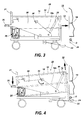
- FIG. 3 shows the exemplary four-wheeled cart 20 being pushed towards the machine 10 developer unit area 12 (after the machine 10 front cover is opened to expose it).
- the cart 20 is pushed by the operator by a convenient high-rise cart handle bar 21 towards the machine until the lower front of the cart abuts a docking bar surface D on the lower front of the machine 10 frame.
- a frontally projecting hook, shelf or foot 22 on the cart 20 passes slightly under docking bar D at that point, as shown in Figs 4-5.
- lateral alignment guides (here vertical bars) 24, 24a on the machine 10 locate the cart 20 laterally as it moves in towards the machine 10 during initial alignment, by engaging lateral alignment spring tabs 25, 25a on the front of the cart 20 at opposite sides of the hook 22.
- Other suitable lateral alignment means may be alternatively used, such as alignment apertures.
- An optional bright colored visual inital alignment aide 27 may be provided higher up on the front of cart 20 to be aligned by the operator with a similarly colored target patch 27a on the machine 10, so that the operator does not have to actually see the alignment of the tabs 25, 25a in the apertures 24, 24a. Note that no vertical alignment, and only a rough lateral (side to side) alignment, is done manually by the operator.
- the final lateral alignment is made in the final part of the movement of the cart against the machine 10, by the tabs 25, 25a laterally aligning the cart as the tabs 25, 25a engage the lateral alignment guides 24, 24a on the machine 10. Laterally sloped or angled surfaces (such as the illustrated "?" shape) of the tabs 25, 25a here, guide the cart into this final lateral alignment achieved with cart 20 abutment against the machine 10.
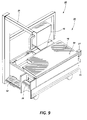
- the cart 20 has two main components, a main frame including the wheels and the pivot 30 axis, and the developer rail unit 32 which is movable relative to the main frame, and which carries the developer unit on rails 18a.
- the hook 22 is fastened to and part of this developer rail unit 32.
- the front of this developer rail unit 32 lifts up in this manner with the downward pedal 26 movement until the hooked lower end 22 thereof engages the machine 10 docking pivot bar D, as shown in Fig. 5.
- the hook 22 engagement with machine pivot bar D prevents further lifting up of the front of the developer rail unit 32, and the rest of the developer rail unit 32 must start to pivot up about pivot bar D.
- This pivoting up of the unit 32 continues through the Fig. 6 position, until, as in Fig.
- a front engagement area of the movable developer rail assembly 32 abuts and is flush with the (vertical) front of the machine 10 in that area, automatically resulting in common vertical and horizontal alignment of the developer rail unit 32 with the machine 10.
- this gas spring 30 compression or piston-stroke absorbs further pedal depression until the downwardly moving pedal 26 reaches a lower stop position (preferably lower than as shown in Fig. 7), at which time the system also reaches or activates a pedal cam lock 34 (described below), which locks the pedal in a down position, thus locking the developer rail unit 32 in this up (aligned) position of Fig. 7.
- a single simple and uncritical downward pedal movement accomplishes all of these above-described vertical movements.
- the cart 20 is automatically in alignment with the machine 10, so that rails pairs 18 and 18a are aligned and have their respective rail ends substantially abutting, so that a developer unit 16 on the cart can be horizontally rolled on its wheels 16a or the like off of the cart 20 on the rails 18a onto the mated and horizontally mutually aligned rails 18 in the machine 10, irrespective of floor conditions or machine height or level variations.
- a developer unit may be rolled into the machine 10 from rails 18a onto rails 18, for loading.
- a developer unit 16 in the machine can be rolled out of the machine on rails 18 and onto rails 18a of an empty cart 20 for unloading. Then, in the case of unloading, the cart 20 is rolled away from the machine and another cart 20 carrying another (replacement or interchange) developer unit is moved into place and aligned or docked in the same manner, for replacing the original developer unit with another developer unit.
- This replacement developer unit will usually, but not necessarily, be a unit loaded with a different color toner material, but otherwise preferably identical or interchangeable.
- a safety interlock system 40 prevents the developer unit transport cart 20 from being undocked from the machine 10 when a developer unit is being moved therebetween. This, or another, safety interlock system also prevents the cart 20 from lowering the developer unit 16 while the developer unit 16 is being moved therebetween in or out of the machine 10.
- This safety interlock system 40 may be, for example, a cam 42 depressed by the wheels 16a or other component of the developer unit when the developer unit is anywhere in said transition between the cart 20 and the machine 10, which cam 42 may connect by flexible cable to the pedal cam lock 34 to prevent the pedal 26 and thus the pedal link or arm 28 from releasing from its fully depressed down position.
- the pedal cam lock 34 may be released, to lower the developer rail unit 32 and any developer unit thereon, simply by stepping on the pedal 26 again. This also allows the cart to be unlocked from its docked position, by also lowering the hook 22 on the cart 20 below docking bar D, so the cart can release from docking bar D and be pulled away (undocked).
- the pedal cam lock 34 may be of various known mechanical latch types which hold a pedal down until it is pressed again to release it to go back up.
- cam lock 34 is of the type wherein a pin 35 rides in, and is controlled by, a triangular cam track 36 and is spring biased in one direction (to the right in Figures 3-8) and wherein the triangular cam track 36 has a one-way gate provided by a flexible leaf spring 37.
- the pin 35 movement is shown in Fig 8 by the dashed line and its arrows.
- Stepping on the pedal 26 a first time moves the pin 35 down over the top of leaf spring 37 so that the leaf spring 37 deflects the pin 35 around the left side of the triangular cam track 36, to the bottom of cam track 36, where spring bias moves the pin 35 to the right until it is deflected by deflector 36a into a stop surface or detent 36b in the lower path of cam track 36.
- the pin 35 stays there in detent 36b after the pedal is first released, holding the pedal down (the illustrated phantom position of pin 35 there), until stepping on the pedal a second time moves down and frees the pin 35 from detent 36b and allows the the pin 35 to move further to the right, so that the release of the pedal 26 a second time allows the pin 35 to ride back up the right side of the triangular cam track 36 and force its way up through the leaf spring 37 gate. That allows the developer rail unit 32 and any developer unit thereon to be lowered (if not otherwise safety locked, as noted).
- the pin 35 here is controlled by the foot pedal 26 by the pin 26 being mounted on the lower end of a swinging arm or link 38.
- the opposite (upper) end of this arm or link 38 is pivotally connected at 39 to the main pivoted link 28 which is pivoted by the foot pedal 26.
- the pin 35 vertical movement is controlled by the foot pedal 26, but the pin 35 can move horizontally under control of its spring bias, here spring 38a, to follow the triangular cam track 36.
- the above-described safety interlock system 40 can be a simple cable actuated cam or pin preventing the horizontal movement of the swinging arm or link 38 by blocking its path and therefore preventing horizontal movement of the pin 35 and therefore prevent the cart from undocking and the developer unit from lowering. This is merely one example of a suitable pedal cam lock 34.
- a tang or projection in the front of the cart extending up from the main frame base of the cart can be provided to engage the developer unit and prevent it from sliding out of the cart in that lowered position (only), or vice versa (a projection from the bottom of the developer unit engaging the cart frame).
- the cart 20 also functions as a device for the convenient servicing, storage, protection from physical damage to, and/or protection from dirt contamination of or from, the developer unit.
- the sides walls of the cart enclose and protect the sides of the developer unit.
- the illustrated horizontal bar or arm of the cart handle A pivotal cover 50 can be provided on the cart 20 to close over the top of the developer unit.
- the cart may be provided with brakes on the wheels.
- means may be provided to help the operator move the cart up and over thick electric cables or other obstacles to movement of the cart wheels on the floor, such as the step area 52 on the back of the cart near pedal 26. By the operator stepping on the step area 52 and pulling back on the cart handle the front of the cart 20 can be lifted or assisted over such floor obstacles.
- An additional interlock may be provided in the machine 10 to prevent the operator from pulling the developer unit out of the machine and onto the floor if there is no cart present.
- a projecting pin or tang on the front of the cart can extend into the machine 10 to release an interlock inside the machine which is otherwise preventing the developer unit from rolling out on its rails 18, such as a pivotal tab or stop normally projecting into the movement path of the developer unit on its rails 18 unless and until it is moved out of the way by said pin or tang on the front of the cart.
Landscapes
- Physics & Mathematics (AREA)
- General Physics & Mathematics (AREA)
- Electrophotography Configuration And Component (AREA)
- Dry Development In Electrophotography (AREA)
Applications Claiming Priority (2)
| Application Number | Priority Date | Filing Date | Title |
|---|---|---|---|
| US757150 | 1991-09-10 | ||
| US07/757,150 US5144369A (en) | 1991-09-10 | 1991-09-10 | Developer unit alignment, removal and interchange system |
Publications (3)
| Publication Number | Publication Date |
|---|---|
| EP0532307A2 true EP0532307A2 (de) | 1993-03-17 |
| EP0532307A3 EP0532307A3 (en) | 1994-06-08 |
| EP0532307B1 EP0532307B1 (de) | 1997-04-09 |
Family
ID=25046571
Family Applications (1)
| Application Number | Title | Priority Date | Filing Date |
|---|---|---|---|
| EP92308203A Expired - Lifetime EP0532307B1 (de) | 1991-09-10 | 1992-09-10 | Ausrichtungs-, Entfern- und Auswechselsystem für eine Entwicklereinheit |
Country Status (3)
| Country | Link |
|---|---|
| US (1) | US5144369A (de) |
| EP (1) | EP0532307B1 (de) |
| DE (1) | DE69218862T2 (de) |
Families Citing this family (19)
| Publication number | Priority date | Publication date | Assignee | Title |
|---|---|---|---|---|
| US5272510A (en) * | 1992-11-13 | 1993-12-21 | Xerox Corporation | Enhanced toner reclaim method and apparatus for a plural color xerographic system |
| US5291243A (en) * | 1993-02-05 | 1994-03-01 | Xerox Corporation | System for electronically printing plural-color tamper-resistant documents |
| US5553843A (en) * | 1994-12-13 | 1996-09-10 | Xerox Corporation | Adapter system to integrate reproduction apparatus to sheet output processing apparatus with lateral registration |
| DE19541062A1 (de) * | 1995-11-03 | 1996-09-26 | Siemens Nixdorf Inf Syst | Entwicklerstation für ein elektrografisches Druck- oder Kopiergerät |
| US5630578A (en) * | 1996-03-25 | 1997-05-20 | Xerox Corporation | Low manual effort system for removably mounting paper handling modules to reproduction machines |
| DE19642763B4 (de) * | 1996-10-16 | 2009-06-10 | Erwin Junker Maschinenfabrik Gmbh | Vorrichtung zum Be- und Entladen von Werkzeugmaschinen |
| JP2001508237A (ja) * | 1997-01-13 | 2001-06-19 | シーメンス アクチエンゲゼルシヤフト | 電気部品を自動取付装置に供給するための装置 |
| US6033175A (en) * | 1998-10-13 | 2000-03-07 | Jenoptik Aktiengesellschaft | Docking mechanism for aligning, coupling and securing a movable cart to a stationary workstation |
| US6205881B1 (en) * | 1998-10-13 | 2001-03-27 | Brooks Automation Gmbh | Device for controlling the drive of mechanisms operating separately from one another |
| JP4429465B2 (ja) * | 1999-12-07 | 2010-03-10 | パナソニック株式会社 | 部品供給部一括交換用カート |
| DE10154743A1 (de) * | 2001-11-09 | 2003-05-22 | Nexpress Solutions Llc | Papiertransportwagen |
| DE202006010803U1 (de) * | 2006-07-13 | 2006-10-26 | Jörg von Seggern GmbH | Anordnung zum Aufnehmen und Übergeben und/oder Transportieren wenigstens eines Funktionsteils einer technischen Einrichtung |
| US8364072B2 (en) * | 2008-09-17 | 2013-01-29 | Xerox Corporation | Reconfigurable sheet transport module |
| US8078082B2 (en) * | 2008-12-10 | 2011-12-13 | Xerox Corporation | Modular printing system |
| US9579241B2 (en) | 2012-10-12 | 2017-02-28 | Steelcase Inc. | Support arrangement with activation mechanism |
| WO2017196907A1 (en) * | 2016-05-11 | 2017-11-16 | Sealed Air Corporation (Us) | Reloading supply cart |
| US10160469B2 (en) * | 2016-07-01 | 2018-12-25 | Steris Inc. | System for transporting and transferring a movable rack assembly and transfer cart assembly therefor |
| US10427434B2 (en) | 2016-07-08 | 2019-10-01 | Xerox Corporation | Printing module replacement cart |
| CH717259B1 (de) * | 2020-03-25 | 2025-10-15 | Castus Sterile Systems Gmbh & Co Kg | System zum Positionieren und Anheben von Lasten. |
Family Cites Families (6)
| Publication number | Priority date | Publication date | Assignee | Title |
|---|---|---|---|---|
| US4097139A (en) * | 1976-09-30 | 1978-06-27 | Xerox Corporation | Reproducing machine having interchangeable developer housings |
| US4671728A (en) * | 1985-07-11 | 1987-06-09 | Applied Power, Inc. | Hydraulic system for a mobile transport vehicle that supports and positions a load relative to a docking structure |
| US4941018A (en) * | 1986-10-28 | 1990-07-10 | Canon Kabushiki Kaisha | Developing device accommodating apparatus and image forming apparatus and developing device |
| US4894684A (en) * | 1987-03-10 | 1990-01-16 | Canon Kabushiki Kaisha | Image forming apparatus with developing device accommodating apparatus |
| JPH0246475A (ja) * | 1988-08-09 | 1990-02-15 | Fuji Xerox Co Ltd | 現像機の脱着装置 |
| US5053820A (en) * | 1990-03-12 | 1991-10-01 | Minnesota Mining & Manufacturing Company | Developing module drive system for an electrographic printer |
-
1991
- 1991-09-10 US US07/757,150 patent/US5144369A/en not_active Expired - Fee Related
-
1992
- 1992-09-10 DE DE69218862T patent/DE69218862T2/de not_active Expired - Fee Related
- 1992-09-10 EP EP92308203A patent/EP0532307B1/de not_active Expired - Lifetime
Also Published As
| Publication number | Publication date |
|---|---|
| US5144369A (en) | 1992-09-01 |
| EP0532307A3 (en) | 1994-06-08 |
| DE69218862D1 (de) | 1997-05-15 |
| DE69218862T2 (de) | 1997-11-27 |
| EP0532307B1 (de) | 1997-04-09 |
Similar Documents
| Publication | Publication Date | Title |
|---|---|---|
| EP0532307B1 (de) | Ausrichtungs-, Entfern- und Auswechselsystem für eine Entwicklereinheit | |
| US6751428B2 (en) | Image forming device and detachably loaded process unit | |
| US5162845A (en) | Image forming apparatus | |
| JP3808964B2 (ja) | 印刷された用紙を複写装置で生成するための複写システム | |
| US20070196149A1 (en) | Waste toner collecting apparatus, image forming apparatus and process cartridge of image forming apparatus | |
| JPH07306577A (ja) | 改良された自動トナー供給蓋ラッチ及びラッチ外しシステム | |
| JPH0854811A (ja) | 画像形成装置 | |
| US4894684A (en) | Image forming apparatus with developing device accommodating apparatus | |
| US5138398A (en) | Support structure holding a plurality of developing devices used in a multi-color image forming apparatus | |
| EP0383983A1 (de) | Bildaufzeichnungsgerät | |
| US4432639A (en) | Reciprocative original carrier locking mechanism | |
| US4895357A (en) | Lighttight film-delivery box and actuator apparatus therefor | |
| EP0398951B1 (de) | Fuehrungssystem zur eingabe und entnahme eines prozessors in ein bzw. aus einem gehaeuse | |
| EP0708048A1 (de) | Verfahren und Gerät zum Einsetzen einer Traägervorratskassette in ein Bildformungssystem | |
| JP2831458B2 (ja) | 給紙装置 | |
| JP3189427B2 (ja) | 画像形成装置の給紙装置 | |
| JPH05204054A (ja) | 写真コピー装置 | |
| JPS593451A (ja) | 画像形成装置 | |
| JPH079728Y2 (ja) | 移載用補助台車 | |
| JPH08234534A (ja) | カラー画像形成装置 | |
| JP3753884B2 (ja) | 画像形成装置 | |
| JP3705176B2 (ja) | 給紙カセット | |
| JP2976123B2 (ja) | 画像形成装置 | |
| JPS63149655A (ja) | 画像生成機 | |
| JP3471166B2 (ja) | 給紙装置 |
Legal Events
| Date | Code | Title | Description |
|---|---|---|---|
| PUAI | Public reference made under article 153(3) epc to a published international application that has entered the european phase |
Free format text: ORIGINAL CODE: 0009012 |
|
| AK | Designated contracting states |
Kind code of ref document: A2 Designated state(s): DE FR GB |
|
| PUAL | Search report despatched |
Free format text: ORIGINAL CODE: 0009013 |
|
| AK | Designated contracting states |
Kind code of ref document: A3 Designated state(s): DE FR GB |
|
| 17P | Request for examination filed |
Effective date: 19941208 |
|
| 17Q | First examination report despatched |
Effective date: 19950711 |
|
| GRAG | Despatch of communication of intention to grant |
Free format text: ORIGINAL CODE: EPIDOS AGRA |
|
| GRAH | Despatch of communication of intention to grant a patent |
Free format text: ORIGINAL CODE: EPIDOS IGRA |
|
| GRAH | Despatch of communication of intention to grant a patent |
Free format text: ORIGINAL CODE: EPIDOS IGRA |
|
| GRAA | (expected) grant |
Free format text: ORIGINAL CODE: 0009210 |
|
| AK | Designated contracting states |
Kind code of ref document: B1 Designated state(s): DE FR GB |
|
| REF | Corresponds to: |
Ref document number: 69218862 Country of ref document: DE Date of ref document: 19970515 |
|
| ET | Fr: translation filed | ||
| PLBE | No opposition filed within time limit |
Free format text: ORIGINAL CODE: 0009261 |
|
| 26N | No opposition filed | ||
| REG | Reference to a national code |
Ref country code: GB Ref legal event code: IF02 |
|
| PGFP | Annual fee paid to national office [announced via postgrant information from national office to epo] |
Ref country code: FR Payment date: 20030909 Year of fee payment: 12 |
|
| PGFP | Annual fee paid to national office [announced via postgrant information from national office to epo] |
Ref country code: GB Payment date: 20030910 Year of fee payment: 12 |
|
| PGFP | Annual fee paid to national office [announced via postgrant information from national office to epo] |
Ref country code: DE Payment date: 20030918 Year of fee payment: 12 |
|
| PG25 | Lapsed in a contracting state [announced via postgrant information from national office to epo] |
Ref country code: GB Free format text: LAPSE BECAUSE OF NON-PAYMENT OF DUE FEES Effective date: 20040910 |
|
| PG25 | Lapsed in a contracting state [announced via postgrant information from national office to epo] |
Ref country code: DE Free format text: LAPSE BECAUSE OF NON-PAYMENT OF DUE FEES Effective date: 20050401 |
|
| GBPC | Gb: european patent ceased through non-payment of renewal fee |
Effective date: 20040910 |
|
| PG25 | Lapsed in a contracting state [announced via postgrant information from national office to epo] |
Ref country code: FR Free format text: LAPSE BECAUSE OF NON-PAYMENT OF DUE FEES Effective date: 20050531 |
|
| REG | Reference to a national code |
Ref country code: FR Ref legal event code: ST |