EP0530727B2 - Wärmespeicherheizgerät - Google Patents
Wärmespeicherheizgerät Download PDFInfo
- Publication number
- EP0530727B2 EP0530727B2 EP92114852A EP92114852A EP0530727B2 EP 0530727 B2 EP0530727 B2 EP 0530727B2 EP 92114852 A EP92114852 A EP 92114852A EP 92114852 A EP92114852 A EP 92114852A EP 0530727 B2 EP0530727 B2 EP 0530727B2
- Authority
- EP
- European Patent Office
- Prior art keywords
- control
- storage heater
- heater according
- sensor
- cartridge
- Prior art date
- Legal status (The legal status is an assumption and is not a legal conclusion. Google has not performed a legal analysis and makes no representation as to the accuracy of the status listed.)
- Expired - Lifetime
Links
Images

Classifications
-
- F—MECHANICAL ENGINEERING; LIGHTING; HEATING; WEAPONS; BLASTING
- F24—HEATING; RANGES; VENTILATING
- F24H—FLUID HEATERS, e.g. WATER OR AIR HEATERS, HAVING HEAT-GENERATING MEANS, e.g. HEAT PUMPS, IN GENERAL
- F24H9/00—Details
- F24H9/20—Arrangement or mounting of control or safety devices
- F24H9/2064—Arrangement or mounting of control or safety devices for air heaters
- F24H9/2071—Arrangement or mounting of control or safety devices for air heaters using electrical energy supply
- F24H9/2078—Storage heaters
-
- F—MECHANICAL ENGINEERING; LIGHTING; HEATING; WEAPONS; BLASTING
- F24—HEATING; RANGES; VENTILATING
- F24H—FLUID HEATERS, e.g. WATER OR AIR HEATERS, HAVING HEAT-GENERATING MEANS, e.g. HEAT PUMPS, IN GENERAL
- F24H15/00—Control of fluid heaters
- F24H15/20—Control of fluid heaters characterised by control inputs
- F24H15/25—Temperature of the heat-generating means in the heater
-
- F—MECHANICAL ENGINEERING; LIGHTING; HEATING; WEAPONS; BLASTING
- F24—HEATING; RANGES; VENTILATING
- F24H—FLUID HEATERS, e.g. WATER OR AIR HEATERS, HAVING HEAT-GENERATING MEANS, e.g. HEAT PUMPS, IN GENERAL
- F24H15/00—Control of fluid heaters
- F24H15/20—Control of fluid heaters characterised by control inputs
- F24H15/258—Outdoor temperature
-
- F—MECHANICAL ENGINEERING; LIGHTING; HEATING; WEAPONS; BLASTING
- F24—HEATING; RANGES; VENTILATING
- F24H—FLUID HEATERS, e.g. WATER OR AIR HEATERS, HAVING HEAT-GENERATING MEANS, e.g. HEAT PUMPS, IN GENERAL
- F24H15/00—Control of fluid heaters
- F24H15/30—Control of fluid heaters characterised by control outputs; characterised by the components to be controlled
- F24H15/345—Control of fans, e.g. on-off control
-
- G—PHYSICS
- G05—CONTROLLING; REGULATING
- G05D—SYSTEMS FOR CONTROLLING OR REGULATING NON-ELECTRIC VARIABLES
- G05D23/00—Control of temperature
- G05D23/19—Control of temperature characterised by the use of electric means
- G05D23/1919—Control of temperature characterised by the use of electric means characterised by the type of controller
- G05D23/1923—Control of temperature characterised by the use of electric means characterised by the type of controller using thermal energy, the cost of which varies in function of time
Definitions
- the invention relates to a heat storage heater with the features of the preamble of Claim 1.
- Such heat storage heaters are basically known. You assign e.g. a ceramic Heat storage core on, which is in one outer casing essentially closed on all sides located. When operating the storage heater is during the night tariff period the memory core heated up. Because the memory core made of materials with high specific heat consists mostly of magnesia stones, it is in the Able to absorb a relatively large amount of heat. This warmth comes later in the day slowly delivered to the room to be heated. It does this by using an air flow Using a blower over the memory core and is heated up by it.
- the charging or recharging of the memory core happens by means of a charge control.
- a charge control Such Charging controls are described in DIN 44574.
- a component of the charge control is a Charge controller.
- Charge controllers are designed to from a signal reflecting the outside temperature to be charged to the amount of the heat to be charged at the upcoming To adjust the outside temperature to the prevailing need. They are in thermomechanical and also in previously known in electronic form and also in DIN 44574.
- a heat storage heater with a charge controller is known as part of the charge control. With the help of a motor-driven fan, thermal energy is extracted from the storage core and fed into the room to be heated.
- the charging and reloading behavior of the known storage heater depends, among other things, on the residual heat contained in the storage core or its heat content.
- a disadvantage of the known charge controller is that the temperature sensors for the heat content of the storage core, based on the dimensions of the storage core itself, can essentially be described as point-like. The sensor must therefore be installed at a representative point on the memory core. The attachment of several sensors for temperature averaging is technically possible, but in terms of cost it involves considerable effort.
- the storage heaters are constantly subject to variable operation, consisting of the details of charging, storage with or without fan support and combinations thereof. This results in differences between the actual heat content and the measured point temperature, even when the sensor coupling point is carefully selected due to the time-delaying material behavior. These deviations can take on considerable dimensions, which can lead to over or under-coverage of the heating requirement. This is especially the case if the EVU grants several charging periods within one day.
- the invention lies based on the task of misinformation at the sensor coupling point to avoid this Charging and recharging behavior of the storage heater better at the actual heat content of the Adapt memory core.
- Claims 2 to 13 relate to a thermomechanical Charge controller.
- Claim 2 relates to a preferred arrangement and the interaction of members of one Charge control. The interaction of this Members are partially described in DIN 44574.
- control element a multi-purpose function. In this way the additional component expenditure for processing the Compensation signals kept low. The improved This is why the charge controller works very inexpensive to reach.
- the charging control can register the changed operation of the storage heater in a simple and safe manner.
- the thermal relay effects a coupling between the control element and the fan, which is also present in conventional storage heating devices. This coupling is available inexpensively and at the same time is technically simple.
- the technically simple structure facilitates the precise operation of the compensation device. An exchange or repair of the compensation device is easily possible.
- the switch action of the thermal relay allows a reliable differentiation of the switching states of the fan.
- Claims 5 to 7 relate to preferred Embodiments of the control element.
- the two-part effect of the control element their simple structure.
- the control cartridge is according to claims 6 and 7 as a mass article available inexpensively. Such tax cartridges easily convert current signals into for the temperature-dependent control sensor necessary Heat signals around.
- control element is suitable, the reference variable in a simple manner the central control unit into a control signal for to convert the charge controller's rear derailleur.
- Claim 10 relates to a double function of Control cartridge. After that, it also serves as Sensor of the reference variable and the compensation signal. Thus, the technically simple remains Structure of the control element with few components receive.
- Compensation signal and reference variable each in a heat signal converted. This is not a separate one Evaluation of both signals required.
- the temperature dependent Control sensor is as a detection element for the reference variable and the compensation signal suitable.
- the electrical current can serve to convert the compensation signal into a heat signal.
- the wiring required for this between the compensation device and the control cartridge can be produced very inexpensively on a circuit board.
- Switchgear of the charge controller uses in technical simply the effective as heat signals Control signals from the control sensor and the residual heat sensor to control charging or recharging of the storage heater.
- Claims 14 to 21 relate to an electronic one Charge controller.
- Claim 14 relates to a preferred arrangement and embodiment of the electronic charge controller.
- Weather sensors and central control units are known components and are described in DIN 44574.
- Central control unit and switching mechanism are coupled to each other by an electronic switching part.
- the switching part can be constructed in a space-saving manner as an electrical circuit or as a microprocessor with, if necessary, further components.
- the electronic processing of reference variable and compensation signal is very precise and takes place in a very short time. This enables the charge controller to react very quickly to changed signals. Faulty components within the switching part can be replaced easily and inexpensively.
- the switching part designed so that depending on the operating state of the Blower and the compensation device that Derailleur receives the appropriate control signals.
- a switching part designed according to claim 17 enables the specification of a setpoint a user person. This is a more flexible adjustment of the charge controller to changed room conditions possible.
- Claim 18 relates to the generation of the control signal for the rear derailleur.
- the switching part with a negative test result further Functions, e.g. triggers a reset pulse. It is also possible to use an optical or acoustic To couple display with the switching part to inform a user whether the storage heater is loaded or not.
- Claims 20 and 21 relate to control charging the storage heater the rear derailleur.
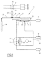
- thermomechanical charge controller 1 shown in FIG. 1 receives a control signal effective as a reference variable 2 from a central control device (not shown here).
- the command variable 2 is dependent on the outside temperature and is fed to the charge controller 1 via a weather sensor and the central control unit. More information on the structure and functioning of a charge control for storage heaters with a weather sensor, central control unit and other components can be found in DIN 44574.
- the command variable 2 becomes a basic cartridge connection 3 fed to a control cartridge 4.
- the control cartridge 4 has a total of three connections, namely the cartridge base connection 3, a center tap 5 and a cartridge connection 6 on.
- the connections 3,5,6 are with a Compensation device 7 and a blower 8 electrically connected.
- the control cartridge 4 can be designed as a resistor or as a winding with the center tap 5. For example, it is also conceivable to use two separate windings, one of which has connections 3 and 5 and the other of which has connections 3 and 6.
- the resistance range between the base cartridge connection 3 and the center tap 5 acts as the base cartridge region 9.
- the resistance range between the center tap 5 and the residual cartridge connection 6 acts as the residual cartridge region 10.
- the control characteristic of the charge controller 1 is characterized by the resistance value of the control cartridge 4.
- the base area 9 of the cartridge forms the control resistor for controlling the charge controller 1 on the basis of the command variable 2 which is dependent on the outside temperature.
- the remaining cartridge area 10 forms the control resistor for the compensation of the control characteristic.
- the compensation device 7 is schematic here as a thermal relay for the compensation of Control curve shown.
- the compensation device 7 here has a relay switch 11 and a temperature-dependent interacting with it Component, e.g. a PTC 12.
- a relay switch 11 On Connection of the relay switch 11 is with the residual cartridge connection 6 connected.
- the other connection of the relay switch 11 is connected to the switch 13 connected.
- the PTC 12 is parallel to the Fan 8 switched.
- the blower 8 is in turn connected to the two motor connections 14, 15.
- the motor connection 15 is also with the Center tap 5 electrically connected.
- the control cartridge 4 is part of a heat sensitive Control 16. Another component this control element 16 is a temperature-dependent Control sensor 17.
- the control sensor 17 is hydraulic Line 18 connected to a switching mechanism 19.
- the switching mechanism 19 is used for the electrical connection and electrical isolation one here Heat storage heater, not shown from a three-phase network.
- the three-phase network is here schematically through the three phase lines 20, 21, 22.
- the switching mechanism 19 is connected via a further hydraulic line 23 to a temperature-dependent residual heat sensor 24.
- the residual heat sensor 24 is arranged in the area of the storage core of the storage heater and measures the heat content of the storage heater.
- the hydraulic lines 18, 23 open into a common connecting line 25 in the area of the switching mechanism 19. For example, there is a gas or a liquid in the lines 18, 23 and the connecting line 25. Depending on the warming or cooling, these substances contract or expand.
- the switching mechanism 19 is thereby hydraulically lowered or raised and thereby switches the three phase switches 26, 27, 28 assigned to the phase lines 20, 21, 22.
- This misinterpretation of the residual heat sensor 24 is compensated for by additional heat supply to the control sensor 17.
- the PTC 12 is heated after a certain time in such a way that the relay switch 11 is switched and the current path between the residual cartridge connection 6 and the switch connection 13 closes. In this way, a current now also flows through the residual cartridge area 10, so that the control cartridge 4 can deliver additional thermal energy to the control sensor 17.
- the compensation device 7, which is designed as a thermal relay, also compensates the control characteristic for a certain run-on time when the fan 8 is switched off again. This is due to the temperature-dependent PTC 12 guaranteed in short time intervals. If the blower 8 remains switched off for a long time, the PTC 12 cools down to such an extent that the current path between the residual cartridge connection 6 and the switch connection 13 is interrupted again.
- the charge controller 1 then again follows the uncompensated control characteristic.
- an electronic charge controller 29 also receives a control signal effective as a reference variable 2 from a central control device.
- the command variable 2 is fed in at a command variable input 30 of a switching part 31.
- the switching part 31 is designed, for example, as an electrical circuit or as a microprocessor with possibly further components.
- a voltage level assigned to the reference variable 2 and acting as a reference level 32 is also connected to an input of the switching part 31.
- the blower 8 is connected analogously to FIG. 1 to a motor connection 14 which acts as a phase and a motor connection 15 which acts as a neutral conductor.
- a characteristic curve input 33 of the switching part 31 is also connected to the motor connection 14. With the fan 8 running, the characteristic input 33 receives a corresponding signal, so that the electronic charge controller 29 operates in accordance with a compensation characteristic. When the blower 8 is switched off, the charge controller 29 follows a basic characteristic curve. These two characteristics are realized by suitable linearization circuits.
- the compensation is also achieved by means of these linearization circuits, so that the switching behavior of the charge controller 29 is as close as possible to the actual heat content of the heat storage heater. A weakening or intensification of the compensation effect within certain working areas of the charge controller 29 is also provided.
- a setpoint adjuster 34 is connected to the switching part 31.
- the setpoint adjuster 34 can be adjusted by a user. In this way, a setpoint for charging the heat storage heater can be specified.
- a switching mechanism 35 decides whether the heat storage heater (not shown in FIG. 2) is charged or is disconnected from the phase lines 20, 21, 22 of the three-phase network.
- the switching mechanism 35 is shown schematically as a thermal relay 36.
- the thermal relay 36 switches the phase switches 26, 27, 28 assigned to the phase lines 20, 21, 22.
- the thermal relay 36 is connected to a control signal connection 37 of the switching part 31 and to the neutral conductor 38 assigned to the phase lines 20, 21, 22. Depending on the control signal applied to the control signal connection 37, the phase switches 26, 27, 28 are switched on or off by the thermal relay 36.
- the control signal at the control signal terminal 37 depends on the outside temperature, the residual heat temperature of the memory core and of Art the characteristic curve.
- the phase line 20 and the neutral conductor 38 are connected to two inputs of the switching part 31.
- the switching part 31 can permanently be checked whether the switching state of the Phase switch 26,27,28 with the control signal on Control signal terminal 37 matches. If there is no
- the switching part 31 may match Functions, e.g. an optical or acoustic Error message, trigger.
- the review can also the switching position of the phase switches 26,27,28 serve to prevent accidental charging by further, not shown here Cancel switching measures.
- the phase switches 26, 27, 28 are initially open.
- the fan 8 is switched on to heat the room in question more.
- the residual heat sensor not shown in FIG. 2, does not register the increased discharge of the heat storage heater.
- the electrical signal at the characteristic curve input 33 causes the charge controller 29 to follow the compensation characteristic.
- a certain lead time or lag time for activating or deactivating the compensation characteristic curve in accordance with the delay effect of the compensation device 7 (FIG. 1) is taken into account by the internal circuit structure of the switching part 31.
- the compensation characteristic is designed as an electrical circuit within the switching part 31 such that a corresponding control signal is present at the control signal connection 37. This control signal causes the phase switches 26, 27, 28 to be closed so that the heat storage heater is recharged in accordance with the increased discharge.
- thermomechanical charge controller 1 and the electronic charge controller 29 provides the influence of the fan run accordingly the switch-on state of the blower motor and / or radiators for heating the memory core to compensate if necessary.
Landscapes
- Engineering & Computer Science (AREA)
- Physics & Mathematics (AREA)
- General Engineering & Computer Science (AREA)
- Thermal Sciences (AREA)
- Chemical & Material Sciences (AREA)
- Combustion & Propulsion (AREA)
- Mechanical Engineering (AREA)
- General Physics & Mathematics (AREA)
- Automation & Control Theory (AREA)
- Central Heating Systems (AREA)
- Resistance Heating (AREA)
- Control Of Resistance Heating (AREA)
- Electrodes For Cathode-Ray Tubes (AREA)
- Cookers (AREA)
- Air-Conditioning For Vehicles (AREA)
- Electrostatic Charge, Transfer And Separation In Electrography (AREA)
- Air Supply (AREA)
- Secondary Cells (AREA)
- Motor Or Generator Cooling System (AREA)
Description
Die Anbringung mehrerer Fühler zur Temperaturmittelung ist zwar technisch möglich, kostenmäßig jedoch mit erheblichem Aufwand verbunden.
Diese Abweichungen können erhebliche Ausmaße annehmen, die zur Über- bzw. Unterdeckung des Heizbedarfes führen können. Dies ist vor allem dann der Fall, wenn innerhalb eines Tages mehrere Aufladeperioden von den EVU gewährt werden.
Die Anpassung des Ladeverhaltens des Speicherheizgerätes an den tatsächlichen Heizbedarf ermöglicht, daß Energie und Energiekosten eingespart werden.
Da Über- und Unterdeckungen des Heizbedarfes vermieden werden, ist auch das Wohlbefinden der Benutzerperson innerhalb des aufzuheizenden Raumes gesteigert.
Die Schalterwirkung des Thermorelais erlaubt eine sichere Unterscheidung der Schaltzustände des Gebläses.
Die hierfür notwendige Verdrahtung zwischen Kompensationsvorrichtung und Steuerpatrone kann sehr kostengünstig auf einer Platine hergestellt werden.
Witterungsfühler und Zentralsteuergerät sind bekannte Bauglieder und in DIN 44574 beschrieben. Zentralsteuergerät und Schaltwerk sind miteinander durch ein elektronisches Schaltteil gekoppelt. Das Schaltteil kann platzsparend als elektrische Schaltung oder als Mikroprozessor mit ggf, weiteren Bausteinen aufgebaut werden. Die elektronische Verarbeitung von Führungsgröße und Kompensationssignal ist sehr genau und erfolgt in sehr kurzer Zeit. Dadurch kann der Aufladeregler auf veränderte Signale sehr schnell reagieren.
Fehlerhafte Bauteile innerhalb des Schaltteils können problemlos und kostengünstig ausgetauscht werden.
- Fig. 1
- eine schematische Darstellung des thermomechanischen Aufladereglers
- Fig 2
- eine schematische Darstellung des elektronischen Aufladereglers.
Näheres zum Aufbau und der Funktionsweise einer Aufladesteuerung für Speicherheizgeräte mit einem Witterungsfühler, Zentralsteuergerät und weiteren Baugliedern ist DIN 44574 entnehmbar.
Die Steuerkennlinie des Aufladereglers 1 ist durch den Widerstandswert der Steuerpatrone 4 charakterisiert. Der Patronengrundbereich 9 bildet den Steuerwiderstand für die Steuerung des Aufladereglers 1 aufgrund der von der Außentemperatur abhängigen Führungsgröße 2.
Der Patronenrestbereich 10 bildet den Steuerwiderstand für die Kompensation der Steuerkennlinie.
Die hydraulischen Leitungen 18,23 münden im Bereich des Schaltwerks 19 in eine gemeinsame Anschlußleitung 25. In den Leitungen 18,23 und der Anschlußleitung 25 befindet sich z.B. ein Gas oder eine Flüssigkeit. Je nach Erwärmung oder Abkühlung ziehen sich diese Stoffe zusammen oder dehnen sich aus. Das Schaltwerk 19 wird dadurch hydraulisch gesenkt oder angehoben und schaltet dadurch die drei den Phasenleitungen 20,21,22 zugeordneten Phasenschalter 26,27,28.
Bei ausgeschaltetem Gebläse 8 und durch den Relaisschalter 11 zwischen dem Patronenrestanschluß 6 und dem Schalteranschluß 13 unterbrochener Strombahn fließt der von der Führungsgröße 2 verursachte Strom über den Patronengrundbereich 9, die Mittelanzapfung 5 und den als Nulleiter wirksamen Motoranschluß 15 gegen Masse ab. Da der Relaisschalter 11 die ihm zugeordnete Strombahn unterbricht, fließt über den Patronenrestbereich 10 kein Strom. Im Patronenrestbereich 10 findet deshalb keine Umwandlung elektrischer Energie in zusätzliche Wärmeenergie für den Steuerfühler 17 statt. Bei eingeschaltetem Gebläse 8 wird das Wärme-Speicherheizgerät stärker entladen. Deshalb ist eine größere Nachladung des Speicherheizgerätes erforderlich. Aufgrund seiner besonderen Anordnung im Bereich des Speicherkerns reicht der Restwärmefühler 24 nicht aus, um die notwendige Nachladung des Speicherheizgerätes zu registrieren. Dadurch entsteht am Schaltwerk 19 ein fehlerhaftes Steuersignal. Diese Fehlinterpretation des Restwärmefühlers 24 wird durch zusätzliche Wärmezufuhr an den Steuerfühler 17 kompensiert.
Bei eingeschaltetem Gebläse 8 ist der PTC 12 nach einer bestimmten Zeit derart erwärmt, daß der Relaisschalter 11 geschaltet wird und die Strombahn zwischen dem Patronenrestanschluß 6 und dem Schalteranschluß 13 schließt.
Auf diese Weise fließt nun auch über den Patronenrestbereich 10 ein Strom, so daß die Steuerpatrone 4 zusätzliche Wärmeenergie an den Steuerfühler 17 abgeben kann.
In Fig. 2 erhält ein elektronischer Aufladeregler 29 ebenfalls ein als Führungsgröße 2 wirksames Steuersignal von einem Zentralsteuergerät. Die Führungsgröße 2 wird an einem Führungsgrößeneingang 30 eines Schaltteils 31 eingespeist.
Das Schaltteil 31 ist z.B. als elektrische Schaltung oder als Mikroprozessor mit ggf. weiteren Bausteinen ausgebildet.
Das Gebläse 8 ist analog zu Fig. 1 an einen als Phase wirksamen Motoranschluß 14 und einen als Nulleiter wirksamen Motoranschluß 15 angeschlossen. Ein Kennlinieneingang 33 des Schaltteils 31 ist ebenfalls mit dem Motoranschluß 14 verbunden. Bei laufendem Gebläse 8 erhält der Kennlinieneingang 33 ein entsprechendes Signal, so daß der elektronische Aufladeregler 29 entsprechend einer Kompensationskennlinie arbeitet.
Bei ausgeschaltetem Gebläse 8 folgt der Aufladeregler 29 einer Grundkennlinie. Diese beiden Kennlinien sind durch geeignete Linearisierungsschaltungen realisiert. Durch diese Linearisierungsschaltungen wird auch die Kompensation erzielt, so daß das Schaltverhalten des Aufladereglers 29 dem tatsächlichen Wärmeinhalt des Wärme-Speicherheizgerätes weitestgehend angenähert wird.
Eine Abschwächung bzw. Verstärkung des Kompensationseffektes innerhalb bestimmter Arbeitsbereiche des Aufladereglers 29 ist ebenfalls vorgesehen.
Abhängig vom an dem Steuersignalanschluß 37 anliegenden Steuersignal werden die Phasenschalter 26,27,28 durch das Thermorelais 36 ein- oder ausgeschaltet.
Eine gewisse Vorlauf- bzw. Nachlaufzeit zur Aktivierung bzw. Deaktivierung der Kompensationskennlinie entsprechend der Verzögerungswirkung der Kompensationsvorrichtung 7 (Fig. 1) ist durch den internen Schaltungsaufbau des Schaltteils 31 berücksichtigt. Auf diese Weise ist gewährleistet, daß der Aufladeregler 29 bei nur kurzzeitigem Ein- bzw. Ausschalten des Gebläses 8 nur einer Kennlinie folgt, so daß ein ständiges Hin- und Herschalten zwischen zwei Kennlinienverläufen verhindert wird.
Die Kompensationskennlinie ist als elektrische Schaltung innerhalb des Schaltteils 31 derart ausgebildet, daß am Steuersignalanschluß 37 ein entsprechendes Steuersignal anliegt.
Dieses Steuersignal veranlaßt, daß die Phasenschalter 26,27,28 geschlossen werden, damit das Wärme-Speicherheizgerät entsprechend der verstärkten Entladung nachgeladen wird.
- 1
- Aufladeregler
- 2
- Führungsgröße
- 3
- Patronengrundanschluß
- 4
- Steuerpatrone
- 5
- Mittelanzapfung
- 6
- Patronenrestanschluß
- 7
- Kompensationsvorrichtung
- 8
- Gebläse
- 9
- Patronengrundbereich
- 10
- Patronenrestbereich
- 11
- Relaisschalter
- 12
- PTC
- 13
- Schalteranschluß
- 14
- Motoranschluß
- 15
- Motoranschluß
- 16
- Steuerelement
- 17
- Steuerfühler
- 18
- Leitung
- 19
- Schaltwerk
- 20
- Phasenleitung
- 21
- "
- 22
- "
- 23
- Leitung
- 24
- Restwärmefühler
- 25
- Anschlußleitung
- 26
- Phasenschalter
- 27
- "
- 28
- "
- 29
- Aufladeregler
- 30
- Führungsgrößeneingang
- 31
- Schaltteil
- 32
- Bezugspegel
- 33
- Kennlinieneingang
- 34
- Sollwertsteller
- 35
- Schaltwerk
- 36
- Thermorelais
- 37
- Steuersignalanschluß
- 38
- Nulleiter
Claims (21)
- Wärmespeicher-Heizgerät mit einer einen Aufladeregler (1) aufweisenden Aufladesteuerung zur Aufladung eines Speicherkerns in Abhängigkeit von dessen Wärmeinhalt und von einer außentemperaturabhängigen Führungsgröße (2) für ein Schaltwerk (19), und mit einem motorgetriebenen Gebläse (8) zur Wärmeabgabe des Speicherkerns, wobei beim Betrieb mit ausgeschaltetem Gebläse (8) das als außentemperaturabhängige Führungsgröße (2) wirksame Steuersignal an das Schaltwerk (19) abgegeben wird,
dadurch gekennzeichnet, daß der Aufladeregler (1) bei eingeschaltetem Gebläse (8) zusätzlich zum als Führungsgröße wirksamen Steuersignal (2) und zu einem von einem Restwärmefühler (24) abgegebenen Steuersignal ein Kompensationssignal für ein fehlerhaftes Steuersignal des Restwärmefühlers (24) an das Schaltwerk (19) abgibt. - Speicherheizgerät nach Anspruch 1,
gekennzeichnet durcheinen Witterungsfühler zur Erfassung des Außentemperaturwertes und zur Weitergabe des Außentemperaturwertes als elektrisches Signal,ein mit dem Witterungsfühler gekoppeltes Zentralsteuergerät zur Weiterverarbeitung des elektrischen Signals zu einer Führungsgrößeein die Führungsgröße verarbeitendes Steuerelement (16) undeinen die Restwärme des Speicherkerns messenden Restwärmefühler (24), wobeidas Steuerelement (16) und der Restwärmefühler (24) die Steuersignale (18,23) für das Schaltwerk (19) liefern. - Speicherheizgerät nach Anspruch 2,
dadurch gekennzeichnet, daß bei eingeschaltetem Gebläse (8) das Steuerelement (16) zusätzlich zur Führungsgröße (2) das Kompensationssignal verarbeitet. - Speicherheizgerät nach Anspruch 3,
gekennzeichnet durch
ein von der Betriebsstellung des Gebläses (8) abhängiges Thermorelais als Kompensationsvorrichtung (7) zur Erzeugung des Kompensationssignals. - Speicherheizgerät nach den Ansprüchen 3 und 4,
dadurch gekennzeichnet, daß das Steuerelement aus einem temperaturabhängigen Steuerfühler (17) und einer Steuerpatrone (4) besteht. - Speicherheizgerät nach Anspruch 5,
dadurch gekennzeichnet, daß die Steuerpatrone (4) ein Widerstand ist. - Speicherheizgerät nach Anspruch 5,
dadurch gekennzeichnet, daß die Steuerpatrone (4) eine Wicklung ist. - Speicherheizgerät nach einem der Ansprüche 5 bis 7,
dadurch gekennzeichnet,daß die Steuerpatrone (4) die Führungsgröße (2) in ein Wärmesignal umsetzt unddaß der Steuerfühler (17) dieses Wärmesignal als Steuersignal (18) an das Schaltwerk (19) abgibt. - Speicherheizgerät nach einem der vorhergehenden Ansprüche,
dadurch gekennzeichnet, daß die Steuersignale (18,23) für das Schaltwerk (19) Wärmesignale sind. - Speicherheizgerät nach einem der vorhergehenden Ansprüche,
gekennzeichnet durch
eine Zweiteilung der Steuerpatrone (4) derart,daß ein Patronengrundbereich (9) permanent als Bindeglied zwischen Zentralsteuergerät und Steuerfühler (17) wirksam ist unddaß ein Patronenrestbereich (10) zuschaltbar ist, wobei bei zugeschaltetem Patronenrestbereich (10) die Steuerpatrone (4) als Bindeglied sowohl zwischen Zentralsteuergerät und Steuerfühler (17) als auch zwischen Kompensationsvorrichtung (7) und Steuerfühler (17) wirksam ist. - Speicherheizgerät nach einem der vorhergehenden Ansprüche,
dadurch gekennzeichnet, daß die Steuerpatrone (4) ausschließlich Wärmesignale an den Steuerfühler (17) abgibt. - Speicherheizgerät nach einem der vorhergehenden Ansprüche,
dadurch gekennzeichnet, daß die Steuerpatrone (4) mit der Kompensationsvorrichtung (7) über eine elektrische Leitung verbunden ist. - Speicherheizgerät nach einem der vorhergehenden Ansprüche,
dadurch gekennzeichnet, daß das Schaltwerk (19) die Ein-/Ausschalter (26,27,28) der Anschlußleitungen (20,21,22) des Speicherheizgerätes hydraulisch schaltet. - Speicherheizgerät nach Anspruch 1,
gekennzeichnet durcheinen Witterungsfühler zur Erfassung des Außentemperaturwertes und zur Weitergabe des Außentemperaturwertes als elektrisches Signal,ein mit dem Witterungsfühler gekoppeltes Zentralsteuergerät zur Weiterverarbeitung des elektrischen Signals zu einer Führungsgröße (2),ein die Führungsgröße (2) verarbeitendes elektronisches Schaltteil (31) undeinen das Steuersignal für das Schaltwerk (35) in Abhängigkeit von der Restwärmetemperatur des Speicherkerns abgebender Steuersignalanschluß (37). - Speicherheizgerät nach Anspruch 14,
dadurch gekennzeichnet,daß das Schaltteil (31) einer Grundkennlinie folgend bei ausgeschaltetem Gebläse (8) und abgeschalteter Kompensationsvorrichtung (7) arbeitet unddaß bei eingeschaltetem Gebläse (8) und eingeschalteter Kompensationsvorrichtung (7) das Schaltteil (31) einer Kompensationskennlinie folgend arbeitet. - Speicherheizgerät nach Anspruch 15,
dadurch gekennzeichnet, daß die Kompensationskennlinie nach dem Einschalten des Gebläses (8) aktiviert ist. - Speicherheizgerät nach einem der vorhergehenden Ansprüche,
dadurch gekennzeichnet, daß ein Sollwertsteller (34) zur Einstellung der Soll-Ladung an das Schaltteil (31) angeschlossen ist. - Speicherheizgerät nach einem der vorhergehenden Ansprüche,
dadurch gekennzeichnet,daß das Steuersignal für das Schaltwerk (35) von den Parametern Außentemperatur, Restwärmetemperatur des Speicherkerns und Art der Kennlinie determiniert ist unddaß das Schaltteil (31) die Parameter zu dem Steuersignal verarbeitet. - Speicherheizgerät nach einem der vorhergehenden Ansprüche,
gekennzeichnet durch
eine Prüffunktion des Schaltteils (31) auf Prüfung des momentanen Schaltzustandes des Schaltwerks (35). - Speicherheizgerät nach einem der vorhergehenden Ansprüche,
dadurch gekennzeichnet, daß das Schaltwerk die Ein-/Ausschalter (26,27,28) der Anschlußleitungen (20,21,22) des Speicherheizgerätes schaltet. - Speicherheizgerät nach Anspruch 20,
dadurch gekennzeichnet, daß das Schaltwerk (35) ein Thermorelais (36) ist.
Applications Claiming Priority (2)
| Application Number | Priority Date | Filing Date | Title |
|---|---|---|---|
| DE4128985 | 1991-08-31 | ||
| DE4128985 | 1991-08-31 |
Publications (3)
| Publication Number | Publication Date |
|---|---|
| EP0530727A1 EP0530727A1 (de) | 1993-03-10 |
| EP0530727B1 EP0530727B1 (de) | 1995-05-24 |
| EP0530727B2 true EP0530727B2 (de) | 2001-10-24 |
Family
ID=6439579
Family Applications (1)
| Application Number | Title | Priority Date | Filing Date |
|---|---|---|---|
| EP92114852A Expired - Lifetime EP0530727B2 (de) | 1991-08-31 | 1992-08-31 | Wärmespeicherheizgerät |
Country Status (5)
| Country | Link |
|---|---|
| EP (1) | EP0530727B2 (de) |
| AT (1) | ATE123133T1 (de) |
| DE (1) | DE59202318D1 (de) |
| ES (1) | ES2041241T5 (de) |
| GR (1) | GR3017016T3 (de) |
Families Citing this family (1)
| Publication number | Priority date | Publication date | Assignee | Title |
|---|---|---|---|---|
| DE10209598C1 (de) * | 2002-03-05 | 2003-10-09 | Kulmbacher Klimageraete | Verfahren zur Aufladeregelung einer Speicherheizung |
Family Cites Families (2)
| Publication number | Priority date | Publication date | Assignee | Title |
|---|---|---|---|---|
| DE3326379A1 (de) * | 1983-07-22 | 1985-01-31 | KKW Kulmbacher Klimageräte-Werk GmbH, 8650 Kulmbach | Regeleinrichtung fuer elektro-waermespeicherheizgeraete |
| DE3525315A1 (de) * | 1985-03-25 | 1986-09-25 | Accum AG, Gossau | Verfahren zum steuern von einzelspeichern |
-
1992
- 1992-08-31 ES ES92114852T patent/ES2041241T5/es not_active Expired - Lifetime
- 1992-08-31 EP EP92114852A patent/EP0530727B2/de not_active Expired - Lifetime
- 1992-08-31 AT AT92114852T patent/ATE123133T1/de active
- 1992-08-31 DE DE59202318T patent/DE59202318D1/de not_active Expired - Lifetime
-
1995
- 1995-08-02 GR GR950402138T patent/GR3017016T3/el unknown
Also Published As
| Publication number | Publication date |
|---|---|
| DE59202318D1 (de) | 1995-06-29 |
| ES2041241T5 (es) | 2002-03-01 |
| EP0530727B1 (de) | 1995-05-24 |
| ATE123133T1 (de) | 1995-06-15 |
| ES2041241T3 (es) | 1995-09-16 |
| ES2041241T1 (es) | 1993-11-16 |
| GR3017016T3 (en) | 1995-11-30 |
| EP0530727A1 (de) | 1993-03-10 |
Similar Documents
| Publication | Publication Date | Title |
|---|---|---|
| DE2619762A1 (de) | Warmluftheizgeraet | |
| EP0789504A2 (de) | Temperaturmesseinrichtung für eine Regelschaltung eines elektrischen Strahlungsheizgeräts | |
| EP0530727B2 (de) | Wärmespeicherheizgerät | |
| DE3839535C2 (de) | ||
| EP3249302B1 (de) | Haushalts-gargerät | |
| DE3446149C2 (de) | ||
| EP0202401A2 (de) | Heizelement | |
| EP0131888A2 (de) | Temperaturabhängige Steuerung für eine Omnibus-Innenraumheizung | |
| DE3042947A1 (de) | Schaltungsanordnung | |
| DE4127493C2 (de) | Thermo-Controller | |
| DE10209598C1 (de) | Verfahren zur Aufladeregelung einer Speicherheizung | |
| DE2539117B2 (de) | Verfahren und Einrichtung zur Aufladung einer elektrischen Speicherheizung | |
| DE2306070C3 (de) | Steuervorrichtung für die Aufheizung von Speicherheizgeräten | |
| CH627897A5 (en) | Device for setting and indicating the power output of an electrical heat generator | |
| DE4023439A1 (de) | Schaltungsanordnung zur regelung der temperatur in einem raum | |
| DE3111989C2 (de) | ||
| DE3337053C1 (de) | Anordnung zur Regelung der Entladung eines Waermespeichers | |
| DE2632668C2 (de) | ||
| DE2152812C3 (de) | Kombinierter Auflade- und Entladeregler für Speicherheizungen | |
| DE2048076C3 (de) | Elektrostatisches Kopiergerat | |
| DE4325379C2 (de) | Verfahren zum Betreiben eines Speicherheizgerätes | |
| DE2021997C (de) | Verfahren zur Regelung von elek tnschen Speicherheizeinrichtungen | |
| DE3912417A1 (de) | Elektronischer raumtemperaturregler | |
| AT297163B (de) | Aufladesteuerung für elektrische Speicherheizungen | |
| DE3134183A1 (de) | Vorrichtung zur temperatursteuerung eines heizkoerpers |
Legal Events
| Date | Code | Title | Description |
|---|---|---|---|
| PUAI | Public reference made under article 153(3) epc to a published international application that has entered the european phase |
Free format text: ORIGINAL CODE: 0009012 |
|
| AK | Designated contracting states |
Kind code of ref document: A1 Designated state(s): AT BE CH DE DK ES FR GB GR IE IT LI LU NL PT |
|
| 17P | Request for examination filed |
Effective date: 19930505 |
|
| GBC | Gb: translation of claims filed (gb section 78(7)/1977) | ||
| EL | Fr: translation of claims filed | ||
| 17Q | First examination report despatched |
Effective date: 19940620 |
|
| GRAA | (expected) grant |
Free format text: ORIGINAL CODE: 0009210 |
|
| AK | Designated contracting states |
Kind code of ref document: B1 Designated state(s): AT BE CH DE DK ES FR GB GR IE IT LI LU NL PT |
|
| PG25 | Lapsed in a contracting state [announced via postgrant information from national office to epo] |
Ref country code: IT Free format text: LAPSE BECAUSE OF FAILURE TO SUBMIT A TRANSLATION OF THE DESCRIPTION OR TO PAY THE FEE WITHIN THE PRESCRIBED TIME-LIMIT;WARNING: LAPSES OF ITALIAN PATENTS WITH EFFECTIVE DATE BEFORE 2007 MAY HAVE OCCURRED AT ANY TIME BEFORE 2007. THE CORRECT EFFECTIVE DATE MAY BE DIFFERENT FROM THE ONE RECORDED. Effective date: 19950524 Ref country code: DK Effective date: 19950524 Ref country code: NL Free format text: LAPSE BECAUSE OF FAILURE TO SUBMIT A TRANSLATION OF THE DESCRIPTION OR TO PAY THE FEE WITHIN THE PRESCRIBED TIME-LIMIT Effective date: 19950524 |
|
| REF | Corresponds to: |
Ref document number: 123133 Country of ref document: AT Date of ref document: 19950615 Kind code of ref document: T |
|
| REG | Reference to a national code |
Ref country code: IE Ref legal event code: FG4D Free format text: 63885 |
|
| REF | Corresponds to: |
Ref document number: 59202318 Country of ref document: DE Date of ref document: 19950629 |
|
| PG25 | Lapsed in a contracting state [announced via postgrant information from national office to epo] |
Ref country code: PT Effective date: 19950824 |
|
| PG25 | Lapsed in a contracting state [announced via postgrant information from national office to epo] |
Ref country code: LU Free format text: LAPSE BECAUSE OF NON-PAYMENT OF DUE FEES Effective date: 19950831 |
|
| ET | Fr: translation filed | ||
| REG | Reference to a national code |
Ref country code: ES Ref legal event code: FG2A Ref document number: 2041241 Country of ref document: ES Kind code of ref document: T3 |
|
| GBT | Gb: translation of ep patent filed (gb section 77(6)(a)/1977) |
Effective date: 19950825 |
|
| REG | Reference to a national code |
Ref country code: GR Ref legal event code: FG4A Free format text: 3017016 |
|
| NLV1 | Nl: lapsed or annulled due to failure to fulfill the requirements of art. 29p and 29m of the patents act | ||
| PG25 | Lapsed in a contracting state [announced via postgrant information from national office to epo] |
Ref country code: IE Free format text: LAPSE BECAUSE OF NON-PAYMENT OF DUE FEES Effective date: 19951212 |
|
| REG | Reference to a national code |
Ref country code: IE Ref legal event code: FD4D Ref document number: 63885 Country of ref document: IE |
|
| PLAV | Examination of admissibility of opposition |
Free format text: ORIGINAL CODE: EPIDOS OPEX |
|
| PLBI | Opposition filed |
Free format text: ORIGINAL CODE: 0009260 |
|
| PLAV | Examination of admissibility of opposition |
Free format text: ORIGINAL CODE: EPIDOS OPEX |
|
| PLBQ | Unpublished change to opponent data |
Free format text: ORIGINAL CODE: EPIDOS OPPO |
|
| PLBI | Opposition filed |
Free format text: ORIGINAL CODE: 0009260 |
|
| PLAV | Examination of admissibility of opposition |
Free format text: ORIGINAL CODE: EPIDOS OPEX |
|
| PLBQ | Unpublished change to opponent data |
Free format text: ORIGINAL CODE: EPIDOS OPPO |
|
| PLBI | Opposition filed |
Free format text: ORIGINAL CODE: 0009260 |
|
| PLAV | Examination of admissibility of opposition |
Free format text: ORIGINAL CODE: EPIDOS OPEX |
|
| PLBF | Reply of patent proprietor to notice(s) of opposition |
Free format text: ORIGINAL CODE: EPIDOS OBSO |
|
| 26 | Opposition filed |
Opponent name: STIEBEL ELTRON GMBH & CO.KG Effective date: 19960130 |
|
| 26 | Opposition filed |
Opponent name: STIEBEL ELTRON GMBH & CO.KG Effective date: 19960130 Opponent name: JOH. VAILLANT GMBH U. CO. Effective date: 19960223 |
|
| 26 | Opposition filed |
Opponent name: JOH. VAILLANT GMBH U. CO. Effective date: 19960223 Opponent name: STIEBEL ELTRON GMBH & CO.KG Effective date: 19960130 Opponent name: INTER CONTROL HERMANN KOEHLER ELEKTRIK GMBH & CO. Effective date: 19960226 |
|
| PLBF | Reply of patent proprietor to notice(s) of opposition |
Free format text: ORIGINAL CODE: EPIDOS OBSO |
|
| PLBF | Reply of patent proprietor to notice(s) of opposition |
Free format text: ORIGINAL CODE: EPIDOS OBSO |
|
| RDAH | Patent revoked |
Free format text: ORIGINAL CODE: EPIDOS REVO |
|
| APAC | Appeal dossier modified |
Free format text: ORIGINAL CODE: EPIDOS NOAPO |
|
| APAE | Appeal reference modified |
Free format text: ORIGINAL CODE: EPIDOS REFNO |
|
| APAC | Appeal dossier modified |
Free format text: ORIGINAL CODE: EPIDOS NOAPO |
|
| APAC | Appeal dossier modified |
Free format text: ORIGINAL CODE: EPIDOS NOAPO |
|
| PLAW | Interlocutory decision in opposition |
Free format text: ORIGINAL CODE: EPIDOS IDOP |
|
| PUAH | Patent maintained in amended form |
Free format text: ORIGINAL CODE: 0009272 |
|
| 27A | Patent maintained in amended form |
Effective date: 20011024 |
|
| AK | Designated contracting states |
Kind code of ref document: B2 Designated state(s): AT BE CH DE DK ES FR GB GR IE IT LI LU NL PT |
|
| REG | Reference to a national code |
Ref country code: CH Ref legal event code: AEN Free format text: AUFRECHTERHALTUNG DES PATENTES IN GEAENDERTER FORM |
|
| REG | Reference to a national code |
Ref country code: GB Ref legal event code: IF02 |
|
| GBTA | Gb: translation of amended ep patent filed (gb section 77(6)(b)/1977) | ||
| PG25 | Lapsed in a contracting state [announced via postgrant information from national office to epo] |
Ref country code: GR Free format text: THE PATENT HAS BEEN ANNULLED BY A DECISION OF A NATIONAL AUTHORITY Effective date: 20020201 |
|
| REG | Reference to a national code |
Ref country code: ES Ref legal event code: DC2A Kind code of ref document: T5 Effective date: 20011218 |
|
| ET3 | Fr: translation filed ** decision concerning opposition | ||
| REG | Reference to a national code |
Ref country code: GR Ref legal event code: EP Ref document number: 20010402513 Country of ref document: GR |
|
| PGFP | Annual fee paid to national office [announced via postgrant information from national office to epo] |
Ref country code: GB Payment date: 20030808 Year of fee payment: 12 |
|
| PGFP | Annual fee paid to national office [announced via postgrant information from national office to epo] |
Ref country code: CH Payment date: 20030826 Year of fee payment: 12 |
|
| PGFP | Annual fee paid to national office [announced via postgrant information from national office to epo] |
Ref country code: GR Payment date: 20030829 Year of fee payment: 12 |
|
| PG25 | Lapsed in a contracting state [announced via postgrant information from national office to epo] |
Ref country code: CH Free format text: LAPSE BECAUSE OF NON-PAYMENT OF DUE FEES Effective date: 20040831 Ref country code: GB Free format text: LAPSE BECAUSE OF NON-PAYMENT OF DUE FEES Effective date: 20040831 Ref country code: LI Free format text: LAPSE BECAUSE OF NON-PAYMENT OF DUE FEES Effective date: 20040831 |
|
| REG | Reference to a national code |
Ref country code: CH Ref legal event code: PL |
|
| GBPC | Gb: european patent ceased through non-payment of renewal fee |
Effective date: 20040831 |
|
| APAH | Appeal reference modified |
Free format text: ORIGINAL CODE: EPIDOSCREFNO |
|
| PLAB | Opposition data, opponent's data or that of the opponent's representative modified |
Free format text: ORIGINAL CODE: 0009299OPPO |
|
| PGFP | Annual fee paid to national office [announced via postgrant information from national office to epo] |
Ref country code: ES Payment date: 20100830 Year of fee payment: 19 |
|
| PGFP | Annual fee paid to national office [announced via postgrant information from national office to epo] |
Ref country code: AT Payment date: 20100820 Year of fee payment: 19 Ref country code: DE Payment date: 20100830 Year of fee payment: 19 Ref country code: FR Payment date: 20100901 Year of fee payment: 19 |
|
| PGFP | Annual fee paid to national office [announced via postgrant information from national office to epo] |
Ref country code: BE Payment date: 20100823 Year of fee payment: 19 |
|
| BERE | Be: lapsed |
Owner name: KULMBACHER KLIMAGERATE-WERK G.M.B.H. *KKW Effective date: 20110831 |
|
| REG | Reference to a national code |
Ref country code: FR Ref legal event code: ST Effective date: 20120430 |
|
| PG25 | Lapsed in a contracting state [announced via postgrant information from national office to epo] |
Ref country code: BE Free format text: LAPSE BECAUSE OF NON-PAYMENT OF DUE FEES Effective date: 20110831 |
|
| REG | Reference to a national code |
Ref country code: DE Ref legal event code: R119 Ref document number: 59202318 Country of ref document: DE Effective date: 20120301 |
|
| PG25 | Lapsed in a contracting state [announced via postgrant information from national office to epo] |
Ref country code: FR Free format text: LAPSE BECAUSE OF NON-PAYMENT OF DUE FEES Effective date: 20110831 |
|
| REG | Reference to a national code |
Ref country code: AT Ref legal event code: MM01 Ref document number: 123133 Country of ref document: AT Kind code of ref document: T Effective date: 20110831 |
|
| REG | Reference to a national code |
Ref country code: ES Ref legal event code: FD2A Effective date: 20121207 |
|
| PG25 | Lapsed in a contracting state [announced via postgrant information from national office to epo] |
Ref country code: AT Free format text: LAPSE BECAUSE OF NON-PAYMENT OF DUE FEES Effective date: 20110831 |
|
| PG25 | Lapsed in a contracting state [announced via postgrant information from national office to epo] |
Ref country code: ES Free format text: LAPSE BECAUSE OF NON-PAYMENT OF DUE FEES Effective date: 20110901 |
|
| PG25 | Lapsed in a contracting state [announced via postgrant information from national office to epo] |
Ref country code: DE Free format text: LAPSE BECAUSE OF NON-PAYMENT OF DUE FEES Effective date: 20120301 |