EP0527397B1 - Dispositif de fabrication des lentilles de contact bifocales - Google Patents
Dispositif de fabrication des lentilles de contact bifocales Download PDFInfo
- Publication number
- EP0527397B1 EP0527397B1 EP92113036A EP92113036A EP0527397B1 EP 0527397 B1 EP0527397 B1 EP 0527397B1 EP 92113036 A EP92113036 A EP 92113036A EP 92113036 A EP92113036 A EP 92113036A EP 0527397 B1 EP0527397 B1 EP 0527397B1
- Authority
- EP
- European Patent Office
- Prior art keywords
- radius
- lens
- symmetry
- distance vision
- vision section
- Prior art date
- Legal status (The legal status is an assumption and is not a legal conclusion. Google has not performed a legal analysis and makes no representation as to the accuracy of the status listed.)
- Expired - Lifetime
Links
- 230000007704 transition Effects 0.000 claims abstract description 7
- 238000004519 manufacturing process Methods 0.000 claims description 2
- 238000006073 displacement reaction Methods 0.000 claims 2
- 230000015572 biosynthetic process Effects 0.000 abstract 1
- 241000219739 Lens Species 0.000 description 25
- 229910003460 diamond Inorganic materials 0.000 description 11
- 239000010432 diamond Substances 0.000 description 11
- 240000004322 Lens culinaris Species 0.000 description 3
- 230000003287 optical effect Effects 0.000 description 3
- 238000000034 method Methods 0.000 description 2
- 238000000926 separation method Methods 0.000 description 2
- 241001422033 Thestylus Species 0.000 description 1
- 239000002537 cosmetic Substances 0.000 description 1
- 230000006735 deficit Effects 0.000 description 1
- 239000000463 material Substances 0.000 description 1
Images


Classifications
-
- G—PHYSICS
- G02—OPTICS
- G02C—SPECTACLES; SUNGLASSES OR GOGGLES INSOFAR AS THEY HAVE THE SAME FEATURES AS SPECTACLES; CONTACT LENSES
- G02C7/00—Optical parts
- G02C7/02—Lenses; Lens systems ; Methods of designing lenses
- G02C7/04—Contact lenses for the eyes
- G02C7/041—Contact lenses for the eyes bifocal; multifocal
-
- B—PERFORMING OPERATIONS; TRANSPORTING
- B24—GRINDING; POLISHING
- B24B—MACHINES, DEVICES, OR PROCESSES FOR GRINDING OR POLISHING; DRESSING OR CONDITIONING OF ABRADING SURFACES; FEEDING OF GRINDING, POLISHING, OR LAPPING AGENTS
- B24B13/00—Machines or devices designed for grinding or polishing optical surfaces on lenses or surfaces of similar shape on other work; Accessories therefor
- B24B13/0012—Machines or devices designed for grinding or polishing optical surfaces on lenses or surfaces of similar shape on other work; Accessories therefor for multifocal lenses
-
- B—PERFORMING OPERATIONS; TRANSPORTING
- B24—GRINDING; POLISHING
- B24B—MACHINES, DEVICES, OR PROCESSES FOR GRINDING OR POLISHING; DRESSING OR CONDITIONING OF ABRADING SURFACES; FEEDING OF GRINDING, POLISHING, OR LAPPING AGENTS
- B24B13/00—Machines or devices designed for grinding or polishing optical surfaces on lenses or surfaces of similar shape on other work; Accessories therefor
- B24B13/06—Machines or devices designed for grinding or polishing optical surfaces on lenses or surfaces of similar shape on other work; Accessories therefor grinding of lenses, the tool or work being controlled by information-carrying means, e.g. patterns, punched tapes, magnetic tapes
-
- G—PHYSICS
- G02—OPTICS
- G02C—SPECTACLES; SUNGLASSES OR GOGGLES INSOFAR AS THEY HAVE THE SAME FEATURES AS SPECTACLES; CONTACT LENSES
- G02C7/00—Optical parts
- G02C7/02—Lenses; Lens systems ; Methods of designing lenses
- G02C7/04—Contact lenses for the eyes
- G02C7/041—Contact lenses for the eyes bifocal; multifocal
- G02C7/045—Sectorial configuration
-
- G—PHYSICS
- G05—CONTROLLING; REGULATING
- G05B—CONTROL OR REGULATING SYSTEMS IN GENERAL; FUNCTIONAL ELEMENTS OF SUCH SYSTEMS; MONITORING OR TESTING ARRANGEMENTS FOR SUCH SYSTEMS OR ELEMENTS
- G05B19/00—Programme-control systems
- G05B19/02—Programme-control systems electric
- G05B19/18—Numerical control [NC], i.e. automatically operating machines, in particular machine tools, e.g. in a manufacturing environment, so as to execute positioning, movement or co-ordinated operations by means of programme data in numerical form
- G05B19/182—Numerical control [NC], i.e. automatically operating machines, in particular machine tools, e.g. in a manufacturing environment, so as to execute positioning, movement or co-ordinated operations by means of programme data in numerical form characterised by the machine tool function, e.g. thread cutting, cam making, tool direction control
- G05B19/184—Generation of cam-like surfaces
Definitions
- the invention relates to a bifocal contact lens according to the preamble of claim 4 and a device according to the preamble of claim 1 for producing such a contact lens.
- a contact lens according to the preamble of claim 4 is known from EP-A-0 248 489.
- the near part is tilted relative to the far part so that the edge of the near part merges smoothly into the surface of the far part.
- the object of the invention is to provide a bifocal contact lens which has a kink-free transition from the far part to the near part, the optical quality in the center of the lens being unaffected. Furthermore, a device should be created with which such a contact lens can be produced.
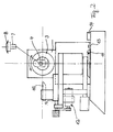
- a support 2 is mounted on a frame 1 and can be moved on a cross slide both along the symmetry axis 22 shown and in a direction transverse thereto.
- the support 2 carries an eccentric head 3 with a lens holder 4 connected to it.
- the lens holder 4 is, as can best be seen from FIG. 2, in the form of a rod which extends parallel to the axis of symmetry of the eccentric head and on a line passing through the axis of symmetry Straight line is displaceable relative to the axis of symmetry.
- the lens holder has a bore 5 into which a mushroom-shaped holder 7, on which the lens blank 8 is clamped, is inserted and held in place by means of a locking screw 6.
- a drive 23 is provided for adjusting the eccentricity of the position of the lens holder 4.
- a carriage 9 with a holder for a diamond stylus 10 is provided.
- the carriage 9 is connected via a bearing to the frame 1 in such a way that the holder for the diamond stylus 10 is on the one hand pivotably arranged on a radius 11, the center of which coincides with the axis of symmetry of the eccentric head 3 when the support 2 is seen in its transverse position in its zero position stands.
- the holder for the diamond stylus 10 itself is displaceable so that its distance from the axis of symmetry 22 of the eccentric head is adjustable.
- the diamond stylus 10 lies with its cutting tip at the level of the axis of symmetry 22.
- a drive 12 is provided for moving the carriage 9 back and forth perpendicular to the axis of symmetry 22 of the eccentric head 3.
- a start switch 13 for switching on the drive 12 and a limit switch 14 for switching off the drive 12 and the drive 23 are provided.
- the device for pivoting the carriage 9 has a release pin 15 which can be adjusted circumferentially to the degree and which, in cooperation with the start switch 13 or limit switch 14, switches the drive 12 on or off. By setting the trigger pin 15, the starting position and thus the zone height of the contact lens can be set.
- a controller 16 is provided which is acted upon on the input side by the output signal from the start switch 13 and limit switch 14 and the extensive setting of the trigger pin 15. On the output side, the control is connected to the drive 12 in the slide 9 and to the drive 23 for adjusting the eccentricity.
- the holder 7 with the clamped lens blank 8 is inserted into the bore 5 of the lens holder 4 in the manner described above, and fixedly mounted by means of the locking screw 6.
- a radius R 1 of, for example, 8 mm is first set in that the diamond stylus 10 corresponds to the radius R 1 the distance from the axis of symmetry of the eccentric head is set.
- the diamond 10 is then moved with the radius R 1 from the upper edge 17 of the lens blank 8 while simultaneously rotating the lens blank by switching on the support 2 and thus cuts the distant part 19 of the lens to be shaped.
- the middle edge 18 passes through the intersection of the axis of symmetry of the eccentric head and the radius of the diamond stylus 10.
- the near part 20 should have a smaller radius R 2 of, for example, 7.5 mm.
- the lens holder 4 on the eccentric head 3 is displaced at the location of the middle edge 18 such that the distance of the lens surfaces from the axis of symmetry 22 is reduced from 8 to 7.5 mm.
- the slide 9 and thus the diamond stylus 10 are displaced towards the center point in such a way that the radius is reduced from previously 8 mm to 7.5 mm.
- the near part 20 is then cut by moving the diamond stylus 10 on the radius 11. This process creates the lens shown in perspective in FIG. 1 with a dividing line between the distant part and the near part along the middle edge 18. In the middle of the lens, the transition is stepless, but the step becomes increasingly larger towards the edge. In the example, the step height is 0.137 mm high with a lens diameter of 9.6 mm.
- the controller 16 drives the drive 12 for the slide and thus the diamond stylus 10 in such a way that while simultaneously pivoting the stylus on the circular slide from the location of the central edge over the preset range of approximately 10 towards the upper edge 17 of the distant part, the radius changes continuously so that at the end of the angular range it is equal to the radius R 2 plus the value of the step height, that is (0.75 + 0.137) mm.
- the lens holder 4 is displaced on the eccentric head 3 such that the distance of the lens surface from the axis of symmetry 23 of R 2 (thus 7.5 mm in the example) is also increased by the zone height at the same time. It is thereby achieved that a section 21 is removed, which extends laterally from the central edge 18 to the preset angular range and in which the surface of the near part 20 merges continuously into the surface of the distant part 19. In the central area of the lens there is no impairment of the optical quality. The edge regions 21 are of no importance for the optical quality of the lens.
- the continuous transition eliminates the cosmetic disadvantages and disadvantages encountered in the prior art during the day.
- the finished lens with the sliding transition is shown in Fig. 1 b.
Landscapes
- Physics & Mathematics (AREA)
- Engineering & Computer Science (AREA)
- Ophthalmology & Optometry (AREA)
- Health & Medical Sciences (AREA)
- General Physics & Mathematics (AREA)
- General Health & Medical Sciences (AREA)
- Optics & Photonics (AREA)
- Mechanical Engineering (AREA)
- Human Computer Interaction (AREA)
- Manufacturing & Machinery (AREA)
- Automation & Control Theory (AREA)
- Grinding And Polishing Of Tertiary Curved Surfaces And Surfaces With Complex Shapes (AREA)
- Eyeglasses (AREA)
Claims (4)
caractérisé en ce que ledit organe de commande (16) est configuré de façon que l'unité d'entraînement (12) ajuste ledit burin (10) à tailler la partie de vision à distance (19) à un premier rayon (Ri ) et à tailler de la partie de vision à proximité (20) à un deuxième, plus petit rayon (R2), et, au dedans une portée angulaire choisie à partir de la marge centrale (18) entre lesdites deux parties de vision, élargit le rayon en continu à partie dudit deuxième rayon (R2) dans ladite partie de vision à distance (19), à poursuite simultanée de l'excentricité grâce à un déplacement approprié dudit porte-lentille (4, 7) à ladite tête excentrique (3), de façon que ladite partie de vision à proximité se convertisse en continu en ladite partie de vision à distance (19).
caractérisé en ce qu'un premier poussoir et un deuxième poussoir (13, 14) sont prévus à l'écart de ladite portée angulaire prédestinée à mettre une unité d'entraînement à entraîner ledit burin dans le ou respectivement hors circuit.
caractérisé en ce que ledit organe de commande (16) est configuré d'une manière que le déplacement approprié dudit porte-lentille (4, 7) à ladite tête excentrique (3) se fasse de façon que l'écart entre le centre sur la surface de la lentille à fabriquer et ledit axe de symétrie soit varié de R1 à R2.
caractérisé en ce qu'une portée de transition (21) est prévue, qui s'étend de ladite partie de vision à proximité (20) dans ladite partie de vision à distance (19) de part et d'autre d'un centre sur la surface de la lentille, au dedans de laquelle portée de transition le rayon de la surface de lentille se convertit en continu dudit deuxième rayon (R2) en ledit premier rayon (R1 ).
Applications Claiming Priority (2)
| Application Number | Priority Date | Filing Date | Title |
|---|---|---|---|
| DE4125707 | 1991-08-02 | ||
| DE4125707A DE4125707C2 (de) | 1991-08-02 | 1991-08-02 | Vorrichtung zum Herstellen einer Bifokal-Contactlinse und damit hergestellte Contactlinse |
Publications (3)
| Publication Number | Publication Date |
|---|---|
| EP0527397A1 EP0527397A1 (fr) | 1993-02-17 |
| EP0527397B1 true EP0527397B1 (fr) | 1995-10-25 |
| EP0527397B2 EP0527397B2 (fr) | 1999-03-03 |
Family
ID=6437604
Family Applications (1)
| Application Number | Title | Priority Date | Filing Date |
|---|---|---|---|
| EP92113036A Expired - Lifetime EP0527397B2 (fr) | 1991-08-02 | 1992-07-30 | Dispositif de fabrication des lentilles de contact bifocales |
Country Status (4)
| Country | Link |
|---|---|
| US (1) | US5430504A (fr) |
| EP (1) | EP0527397B2 (fr) |
| AT (1) | ATE129449T1 (fr) |
| DE (2) | DE4125707C2 (fr) |
Families Citing this family (18)
| Publication number | Priority date | Publication date | Assignee | Title |
|---|---|---|---|---|
| IL110740A (en) * | 1994-08-22 | 1997-03-18 | Hanita Lenses | Multifocal contact lens |
| US5929969A (en) * | 1995-05-04 | 1999-07-27 | Johnson & Johnson Vision Products, Inc. | Multifocal ophthalmic lens |
| US5724120A (en) * | 1995-10-02 | 1998-03-03 | Svochak; Jan B. | Multifocal contact lens and method and apparatus for making the same |
| EP0854769B1 (fr) * | 1995-10-14 | 2002-02-27 | Carl Zeiss | Procede de fabrication de surfaces optiques et machine a usiner propre a mettre en oeuvre ce procede |
| US5980040A (en) * | 1997-06-30 | 1999-11-09 | Wesley Jessen Corporation | Pinhole lens and contact lens |
| WO2000008516A1 (fr) | 1998-08-06 | 2000-02-17 | Lett John B W | Lentilles multifocales aspheriques |
| FR2782663B1 (fr) | 1998-08-28 | 2000-11-17 | Denis Girod | Procede de realisation d'un verre correcteur a foyers multiples, et systeme de mise en oeuvre d'un tel procede |
| WO2000036457A1 (fr) | 1998-12-16 | 2000-06-22 | Wesley Jessen Corporation | Lentilles de contact multifocales a surfaces aspheriques |
| US6467903B1 (en) * | 2000-03-31 | 2002-10-22 | Ocular Sciences, Inc. | Contact lens having a uniform horizontal thickness profile |
| US7628485B2 (en) * | 2000-03-31 | 2009-12-08 | Coopervision International Holding Company, Lp | Contact lens having a uniform horizontal thickness profile |
| CA2313830A1 (fr) * | 2000-07-13 | 2002-01-13 | Micro Optics Design Corporation | Tour au diamant a pointe unique dote d'un systeme antivibratoire |
| US6746118B2 (en) * | 2001-07-17 | 2004-06-08 | Soft Focal Company, Inc. | Bifocal contact lens with secondary prism |
| WO2004109368A2 (fr) * | 2003-05-30 | 2004-12-16 | Scientific Optics, Inc. | Lentille de contact a peripherie presentant une forme specifique |
| US6871953B1 (en) | 2003-09-29 | 2005-03-29 | Softfocal Company, Inc. | Contact lens with transition |
| US20050274241A1 (en) * | 2004-06-12 | 2005-12-15 | Mandell Robert B | Method of making a contact lens with prism |
| US8272734B2 (en) * | 2004-11-16 | 2012-09-25 | Essilor International, S.A. | Non-progressive multifocal lens with large near/intermediate area |
| US20060103806A1 (en) * | 2004-11-16 | 2006-05-18 | Prio Corporation | Non-progressive multi-focal lens with large near/intermediate area |
| US9885882B2 (en) | 2016-02-03 | 2018-02-06 | Diversified Ophthalmics, Inc. | Progressive contact lens |
Family Cites Families (7)
| Publication number | Priority date | Publication date | Assignee | Title |
|---|---|---|---|---|
| DE1158281B (de) * | 1961-08-03 | 1963-11-28 | Wilhelm Peter Soehnges | Cornealkontaktlinse |
| DE2106499A1 (de) * | 1971-02-11 | 1972-10-05 | Optikus, N.A. Günther, 4630 Bochum | Mehrstärken-Contact-Linse |
| US3913274A (en) * | 1974-08-09 | 1975-10-21 | Morgan B Raiford | Method and apparatus for making integrated multifocal lenses |
| DE3110624C2 (de) * | 1981-03-18 | 1983-12-29 | Titmus Eurocon Kontaktlinsen Gmbh & Co Kg, 8750 Aschaffenburg | Vorrichtung zum Herstellen einer Kontaktlinse |
| CA1265688A (fr) * | 1984-10-17 | 1990-02-13 | Alain Rainville | Lentille corneenne a double foyer et methode de production |
| EP0248489A3 (fr) * | 1986-06-02 | 1989-09-06 | Gregory N. Miller | Lentille de contact et sa méthode de fabrication |
| CH674325A5 (en) * | 1987-10-26 | 1990-05-31 | Max Gfeller Ag | Machine for producing workpieces with concave or convex surfaces - has table which can be swung about vertical axis and carrying slide which carries workpiece |
-
1991
- 1991-08-02 DE DE4125707A patent/DE4125707C2/de not_active Expired - Fee Related
-
1992
- 1992-07-30 AT AT92113036T patent/ATE129449T1/de not_active IP Right Cessation
- 1992-07-30 EP EP92113036A patent/EP0527397B2/fr not_active Expired - Lifetime
- 1992-07-30 DE DE59204110T patent/DE59204110D1/de not_active Expired - Fee Related
- 1992-07-31 US US07/923,222 patent/US5430504A/en not_active Expired - Fee Related
Also Published As
| Publication number | Publication date |
|---|---|
| DE4125707A1 (de) | 1993-02-04 |
| DE4125707C2 (de) | 1994-08-04 |
| EP0527397A1 (fr) | 1993-02-17 |
| US5430504A (en) | 1995-07-04 |
| ATE129449T1 (de) | 1995-11-15 |
| EP0527397B2 (fr) | 1999-03-03 |
| DE59204110D1 (de) | 1995-11-30 |
Similar Documents
| Publication | Publication Date | Title |
|---|---|---|
| EP0527397B1 (fr) | Dispositif de fabrication des lentilles de contact bifocales | |
| DE69021868T2 (de) | Herstellungsgerät für Kunststofflinsen und Verfahren. | |
| DE2612173B2 (de) | Fahrbare Schienenschleifmaschine | |
| EP1719585A2 (fr) | Machine de meulage de pièces optiques, en particuliere de verres à lunettes en plastique | |
| DE69804240T2 (de) | Zentriervorrichtung für doppeltverzahnte zahnräder und verfahren zur herstellung von derartigen zahnrädern | |
| DE2428426B2 (de) | Vorrichtung zum Stirnschleifen von versenkt arbeitenden Schneidwerkzeugen | |
| DE69405296T2 (de) | Haltevorrichtung für ophtalmische Linse | |
| DE2747989A1 (de) | Bohrmaschine, insbesondere fuer glas- oder keramikwerkstuecke | |
| DE3512761A1 (de) | Vorrichtung zur automatischen steuerung der schwenk- und translationsbewegungen des schlittens einer kantenschleifmaschine fuer brillenglaeser | |
| DE3520027C2 (fr) | ||
| DE3851677T2 (de) | Verfahren zum Herstellen von Hydrogel-Kontaktlinsen mit asphaerischen Oberflächen. | |
| WO2002043919A1 (fr) | Procede et un dispositif pour fabriquer des moules pour courroies dentees | |
| DE102004031584B4 (de) | Schärfmaschine zum Scharfschleifen von Klingen | |
| DE10013649A1 (de) | Zusatzschleifwerkzeug an einer Brillenglasrandschleifmaschine | |
| DE3110624C2 (de) | Vorrichtung zum Herstellen einer Kontaktlinse | |
| DE2452396A1 (de) | Profilschleifmaschine | |
| DE4107227A1 (de) | Positionierhilfe fuer messerhalter | |
| DE3809821C2 (fr) | ||
| DE2415006A1 (de) | Verfahren und vorrichtung zur herstellung von fensterrahmen mit glashalteleiste aus holz | |
| DE19500946C1 (de) | Winkelverstellbarer Werkstücksitz | |
| DE3105100C2 (de) | Maschine zum Schleifen einer Nut in die Umfangsfläche eines unrunden Brillenglases | |
| DE3814670A1 (de) | Brillenglasrandschleifmaschine | |
| DE2709675A1 (de) | Vorrichtung zur genauen positionierung einer elektrostatischen heftvorrichtung | |
| DE2930997A1 (de) | Maschine zum feinbearbeiten, z.b. schaben, von zahnflanken | |
| EP1379902B1 (fr) | Procede d'ajustage, notamment procede d'ajustage laser et actionneur correspondant |
Legal Events
| Date | Code | Title | Description |
|---|---|---|---|
| PUAI | Public reference made under article 153(3) epc to a published international application that has entered the european phase |
Free format text: ORIGINAL CODE: 0009012 |
|
| AK | Designated contracting states |
Kind code of ref document: A1 Designated state(s): AT BE CH DE DK ES FR GB GR IT LI LU NL PT |
|
| 17P | Request for examination filed |
Effective date: 19930127 |
|
| 17Q | First examination report despatched |
Effective date: 19940603 |
|
| GRAA | (expected) grant |
Free format text: ORIGINAL CODE: 0009210 |
|
| AK | Designated contracting states |
Kind code of ref document: B1 Designated state(s): AT BE CH DE DK ES FR GB GR IT LI LU NL PT |
|
| PG25 | Lapsed in a contracting state [announced via postgrant information from national office to epo] |
Ref country code: GR Free format text: LAPSE BECAUSE OF FAILURE TO SUBMIT A TRANSLATION OF THE DESCRIPTION OR TO PAY THE FEE WITHIN THE PRESCRIBED TIME-LIMIT Effective date: 19951025 Ref country code: GB Effective date: 19951025 Ref country code: FR Effective date: 19951025 Ref country code: ES Free format text: THE PATENT HAS BEEN ANNULLED BY A DECISION OF A NATIONAL AUTHORITY Effective date: 19951025 Ref country code: DK Effective date: 19951025 Ref country code: BE Effective date: 19951025 |
|
| REF | Corresponds to: |
Ref document number: 129449 Country of ref document: AT Date of ref document: 19951115 Kind code of ref document: T |
|
| ITF | It: translation for a ep patent filed | ||
| REF | Corresponds to: |
Ref document number: 59204110 Country of ref document: DE Date of ref document: 19951130 |
|
| REG | Reference to a national code |
Ref country code: CH Ref legal event code: NV Representative=s name: R. A. EGLI & CO. PATENTANWAELTE |
|
| PG25 | Lapsed in a contracting state [announced via postgrant information from national office to epo] |
Ref country code: PT Effective date: 19960125 |
|
| EN | Fr: translation not filed | ||
| GBV | Gb: ep patent (uk) treated as always having been void in accordance with gb section 77(7)/1977 [no translation filed] |
Effective date: 19951025 |
|
| PG25 | Lapsed in a contracting state [announced via postgrant information from national office to epo] |
Ref country code: LU Free format text: LAPSE BECAUSE OF NON-PAYMENT OF DUE FEES Effective date: 19960731 |
|
| PLBI | Opposition filed |
Free format text: ORIGINAL CODE: 0009260 |
|
| PLBF | Reply of patent proprietor to notice(s) of opposition |
Free format text: ORIGINAL CODE: EPIDOS OBSO |
|
| 26 | Opposition filed |
Opponent name: CIBA-GEIGY AG Effective date: 19960725 |
|
| NLR1 | Nl: opposition has been filed with the epo |
Opponent name: CIBA-GEIGY AG |
|
| PLBF | Reply of patent proprietor to notice(s) of opposition |
Free format text: ORIGINAL CODE: EPIDOS OBSO |
|
| PLAB | Opposition data, opponent's data or that of the opponent's representative modified |
Free format text: ORIGINAL CODE: 0009299OPPO |
|
| R26 | Opposition filed (corrected) |
Opponent name: NOVARTIS AG PATENT AND TRADEMARK DEPT. Effective date: 19960725 |
|
| NLR1 | Nl: opposition has been filed with the epo |
Opponent name: NOVARTIS AG PATENT AND TRADEMARK DEPT. |
|
| PLAW | Interlocutory decision in opposition |
Free format text: ORIGINAL CODE: EPIDOS IDOP |
|
| PGFP | Annual fee paid to national office [announced via postgrant information from national office to epo] |
Ref country code: AT Payment date: 19980723 Year of fee payment: 7 |
|
| PLAW | Interlocutory decision in opposition |
Free format text: ORIGINAL CODE: EPIDOS IDOP |
|
| PUAH | Patent maintained in amended form |
Free format text: ORIGINAL CODE: 0009272 |
|
| STAA | Information on the status of an ep patent application or granted ep patent |
Free format text: STATUS: PATENT MAINTAINED AS AMENDED |
|
| 27A | Patent maintained in amended form |
Effective date: 19990303 |
|
| AK | Designated contracting states |
Kind code of ref document: B2 Designated state(s): AT BE CH DE DK ES FR GB GR IT LI LU NL PT |
|
| REG | Reference to a national code |
Ref country code: CH Ref legal event code: AEN Free format text: AUFRECHTERHALTUNG DES PATENTES IN GEAENDERTER FORM |
|
| NLR2 | Nl: decision of opposition | ||
| ITF | It: translation for a ep patent filed | ||
| EN | Fr: translation not filed | ||
| PG25 | Lapsed in a contracting state [announced via postgrant information from national office to epo] |
Ref country code: AT Free format text: LAPSE BECAUSE OF NON-PAYMENT OF DUE FEES Effective date: 19990730 |
|
| NLR3 | Nl: receipt of modified translations in the netherlands language after an opposition procedure | ||
| PGFP | Annual fee paid to national office [announced via postgrant information from national office to epo] |
Ref country code: CH Payment date: 20000721 Year of fee payment: 9 |
|
| PGFP | Annual fee paid to national office [announced via postgrant information from national office to epo] |
Ref country code: NL Payment date: 20000725 Year of fee payment: 9 |
|
| PGFP | Annual fee paid to national office [announced via postgrant information from national office to epo] |
Ref country code: DE Payment date: 20000728 Year of fee payment: 9 |
|
| PG25 | Lapsed in a contracting state [announced via postgrant information from national office to epo] |
Ref country code: LI Free format text: LAPSE BECAUSE OF NON-PAYMENT OF DUE FEES Effective date: 20010731 Ref country code: CH Free format text: LAPSE BECAUSE OF NON-PAYMENT OF DUE FEES Effective date: 20010731 |
|
| PG25 | Lapsed in a contracting state [announced via postgrant information from national office to epo] |
Ref country code: NL Free format text: LAPSE BECAUSE OF NON-PAYMENT OF DUE FEES Effective date: 20020201 |
|
| REG | Reference to a national code |
Ref country code: CH Ref legal event code: PL |
|
| NLV4 | Nl: lapsed or anulled due to non-payment of the annual fee |
Effective date: 20020201 |
|
| PG25 | Lapsed in a contracting state [announced via postgrant information from national office to epo] |
Ref country code: DE Free format text: LAPSE BECAUSE OF NON-PAYMENT OF DUE FEES Effective date: 20020501 |
|
| PG25 | Lapsed in a contracting state [announced via postgrant information from national office to epo] |
Ref country code: IT Free format text: LAPSE BECAUSE OF NON-PAYMENT OF DUE FEES;WARNING: LAPSES OF ITALIAN PATENTS WITH EFFECTIVE DATE BEFORE 2007 MAY HAVE OCCURRED AT ANY TIME BEFORE 2007. THE CORRECT EFFECTIVE DATE MAY BE DIFFERENT FROM THE ONE RECORDED. Effective date: 20050730 |