EP0854769B1 - Procede de fabrication de surfaces optiques et machine a usiner propre a mettre en oeuvre ce procede - Google Patents
Procede de fabrication de surfaces optiques et machine a usiner propre a mettre en oeuvre ce procede Download PDFInfo
- Publication number
- EP0854769B1 EP0854769B1 EP96946356A EP96946356A EP0854769B1 EP 0854769 B1 EP0854769 B1 EP 0854769B1 EP 96946356 A EP96946356 A EP 96946356A EP 96946356 A EP96946356 A EP 96946356A EP 0854769 B1 EP0854769 B1 EP 0854769B1
- Authority
- EP
- European Patent Office
- Prior art keywords
- blank
- processing machine
- machine according
- turning tool
- axis
- Prior art date
- Legal status (The legal status is an assumption and is not a legal conclusion. Google has not performed a legal analysis and makes no representation as to the accuracy of the status listed.)
- Expired - Lifetime
Links
Images


Classifications
-
- B—PERFORMING OPERATIONS; TRANSPORTING
- B24—GRINDING; POLISHING
- B24B—MACHINES, DEVICES, OR PROCESSES FOR GRINDING OR POLISHING; DRESSING OR CONDITIONING OF ABRADING SURFACES; FEEDING OF GRINDING, POLISHING, OR LAPPING AGENTS
- B24B13/00—Machines or devices designed for grinding or polishing optical surfaces on lenses or surfaces of similar shape on other work; Accessories therefor
- B24B13/06—Machines or devices designed for grinding or polishing optical surfaces on lenses or surfaces of similar shape on other work; Accessories therefor grinding of lenses, the tool or work being controlled by information-carrying means, e.g. patterns, punched tapes, magnetic tapes
-
- B—PERFORMING OPERATIONS; TRANSPORTING
- B23—MACHINE TOOLS; METAL-WORKING NOT OTHERWISE PROVIDED FOR
- B23Q—DETAILS, COMPONENTS, OR ACCESSORIES FOR MACHINE TOOLS, e.g. ARRANGEMENTS FOR COPYING OR CONTROLLING; MACHINE TOOLS IN GENERAL CHARACTERISED BY THE CONSTRUCTION OF PARTICULAR DETAILS OR COMPONENTS; COMBINATIONS OR ASSOCIATIONS OF METAL-WORKING MACHINES, NOT DIRECTED TO A PARTICULAR RESULT
- B23Q11/00—Accessories fitted to machine tools for keeping tools or parts of the machine in good working condition or for cooling work; Safety devices specially combined with or arranged in, or specially adapted for use in connection with, machine tools
- B23Q11/0032—Arrangements for preventing or isolating vibrations in parts of the machine
-
- B—PERFORMING OPERATIONS; TRANSPORTING
- B24—GRINDING; POLISHING
- B24B—MACHINES, DEVICES, OR PROCESSES FOR GRINDING OR POLISHING; DRESSING OR CONDITIONING OF ABRADING SURFACES; FEEDING OF GRINDING, POLISHING, OR LAPPING AGENTS
- B24B13/00—Machines or devices designed for grinding or polishing optical surfaces on lenses or surfaces of similar shape on other work; Accessories therefor
-
- B—PERFORMING OPERATIONS; TRANSPORTING
- B23—MACHINE TOOLS; METAL-WORKING NOT OTHERWISE PROVIDED FOR
- B23Q—DETAILS, COMPONENTS, OR ACCESSORIES FOR MACHINE TOOLS, e.g. ARRANGEMENTS FOR COPYING OR CONTROLLING; MACHINE TOOLS IN GENERAL CHARACTERISED BY THE CONSTRUCTION OF PARTICULAR DETAILS OR COMPONENTS; COMBINATIONS OR ASSOCIATIONS OF METAL-WORKING MACHINES, NOT DIRECTED TO A PARTICULAR RESULT
- B23Q2230/00—Special operations in a machine tool
- B23Q2230/004—Using a cutting tool reciprocating at high speeds, e.g. "fast tool"
-
- Y—GENERAL TAGGING OF NEW TECHNOLOGICAL DEVELOPMENTS; GENERAL TAGGING OF CROSS-SECTIONAL TECHNOLOGIES SPANNING OVER SEVERAL SECTIONS OF THE IPC; TECHNICAL SUBJECTS COVERED BY FORMER USPC CROSS-REFERENCE ART COLLECTIONS [XRACs] AND DIGESTS
- Y10—TECHNICAL SUBJECTS COVERED BY FORMER USPC
- Y10T—TECHNICAL SUBJECTS COVERED BY FORMER US CLASSIFICATION
- Y10T82/00—Turning
- Y10T82/12—Radially moving rotating tool inside bore
- Y10T82/125—Tool simultaneously moving axially
-
- Y—GENERAL TAGGING OF NEW TECHNOLOGICAL DEVELOPMENTS; GENERAL TAGGING OF CROSS-SECTIONAL TECHNOLOGIES SPANNING OVER SEVERAL SECTIONS OF THE IPC; TECHNICAL SUBJECTS COVERED BY FORMER USPC CROSS-REFERENCE ART COLLECTIONS [XRACs] AND DIGESTS
- Y10—TECHNICAL SUBJECTS COVERED BY FORMER USPC
- Y10T—TECHNICAL SUBJECTS COVERED BY FORMER US CLASSIFICATION
- Y10T82/00—Turning
- Y10T82/14—Axial pattern
- Y10T82/141—Axial pattern having transverse tool and templet guide
- Y10T82/143—Axial pattern having transverse tool and templet guide having electrical actuator
-
- Y—GENERAL TAGGING OF NEW TECHNOLOGICAL DEVELOPMENTS; GENERAL TAGGING OF CROSS-SECTIONAL TECHNOLOGIES SPANNING OVER SEVERAL SECTIONS OF THE IPC; TECHNICAL SUBJECTS COVERED BY FORMER USPC CROSS-REFERENCE ART COLLECTIONS [XRACs] AND DIGESTS
- Y10—TECHNICAL SUBJECTS COVERED BY FORMER USPC
- Y10T—TECHNICAL SUBJECTS COVERED BY FORMER US CLASSIFICATION
- Y10T82/00—Turning
- Y10T82/25—Lathe
- Y10T82/2502—Lathe with program control
-
- Y—GENERAL TAGGING OF NEW TECHNOLOGICAL DEVELOPMENTS; GENERAL TAGGING OF CROSS-SECTIONAL TECHNOLOGIES SPANNING OVER SEVERAL SECTIONS OF THE IPC; TECHNICAL SUBJECTS COVERED BY FORMER USPC CROSS-REFERENCE ART COLLECTIONS [XRACs] AND DIGESTS
- Y10—TECHNICAL SUBJECTS COVERED BY FORMER USPC
- Y10T—TECHNICAL SUBJECTS COVERED BY FORMER US CLASSIFICATION
- Y10T82/00—Turning
- Y10T82/25—Lathe
- Y10T82/2531—Carriage feed
- Y10T82/2533—Control
Definitions
- the invention relates to a method for producing optical surfaces, especially of ophthalmic lenses and molded shells for the production of ophthalmic lenses (especially aspherical plastic lenses), as well as a Processing machine for performing the method.
- a device according to the preamble of claim 1 and a method according to the preamble of claim 20 are known from EP-A-0 439 425.
- Optical surfaces and especially ophthalmic lenses with complicated Geometry can now be made of silicate glass or plastic getting produced.
- silicate lenses they are made by grinding and subsequent Polishing made.
- Plastic lenses are made by casting in a previously made Negative form made.
- the negative forms, so-called molded shells, are made Silicate glass with the same method as in the production of ophthalmic lenses, also produced by grinding and polishing.
- a disadvantage of this procedure is that, in particular for the production of ophthalmic lenses all required geometric shapes are kept in stock have to.
- the invention has for its object to provide a device and a method, with what geometrically complex shaped optical surfaces and especially ophthalmic ones Lenses and molded shells for the production of ophthalmic lenses according to individual Data specification can be made directly in a single process step, whereby no or at least only slight reworking to complete the optical surfaces and in particular the ophthalmic lenses and molded shells for manufacturing ophthalmic lenses should be needed.
- a tool stylus can move so quickly by the method according to the invention be that those occurring in the circumferential direction, due to the aspherical shape Changes in height can be worked out from a plastic blank.
- the stylus can have a very small radius, which makes the intervention almost punctiform becomes.
- the stylus can also have a radius of several millimeters. It can be set with a monocrystalline diamond.
- the surface created is usually ready for use. May be necessary a little reworking to make it usable Polishing. The shape is completely determined by the turning process and by the polishing no longer changed.
- the surface can also be e.g. usable by dipping in paint be made.
- the process can also be used to manufacture molded shells ophthalmic lenses, e.g. made of metal or ceramic.
- polishing is only required to a very small extent.
- optical surfaces e.g. other lenses or mirrors with complicated, non-rotationally symmetrical Shape.
- this concerns the production of molded shells e.g. for the production of ophthalmic lenses. All markings can also be used in the molded shells later orientation of the lens and other signs can be attached.
- the turning tool performs a pivoting movement relative to the spindle.
- the blank can additionally pivoted when rotating around a center point lying on the Z axis become.
- the turning tool can also be rotated by one center point lying on the Z axis.
- the deflection of the lens material of the material does not require fast tool movements, you can do this Movement either by a slow Z movement or by a swivel movement replace, which is superimposed on the fast sterndrive.
- the fast Z movement must then be used to manufacture e.g. Progressive lenses only have a stroke of approx. 1 mm to have. This procedure has the particular advantage that the shape used area of the turning tool becomes smaller. Uneven wear on the The turning tool then has minor effects.
- a problem with every turning process is the singularity in the middle of the workpiece. It can therefore be provided in a preferred manner that the blank in two slightly off-axis positions deviating from the turning center.
- the blank is machined so that the respective turning center is just through the process is reached in the other position. So you don't turn up to Spindle axis.
- the rotary movement at the edge can be void. This can be avoided by, according to the invention, the path distances in the X direction varied. This then also requires a corresponding one for this feed drive Dynamics, e.g. by applying harmonic vibrations can. Dynamic mass balancing is also advantageous for this.
- Dynamic mass balance requires that a second movement be equal to one large mass must be executed with the opposite direction of movement. you can use this collinear motion to simultaneously move the front and back e.g. a plastic lens or a second ophthalmic lens or one to process the second molded shell for the production of ophthalmic lenses.
- a plastic lens or a second ophthalmic lens or one to process the second molded shell for the production of ophthalmic lenses Depending on The surface design and the blank can be used by simultaneously processing the Front and back brought about mass balancing of the two opposing fast ones Tools are sufficient to achieve the acceleration caused by the turning tools To absorb reaction force. If such compensation is not fully achieved, a third collinear mass balance may be required.
- the position of the tool movement in the Z direction should preferably be at least 0.0005mm can be determined exactly.
- Measuring systems with at least 0.0005mm resolution and the required length are z.
- B. available as opto-electronically scanned scales or laser interferometer.
- Optoelectronic rotary encoders are suitable for determining the position of the rotary movement.
- Tachometers for determining the current movement speeds are also available.
- all of the Parameters describing the system state can be fed to a digital control loop and the control taking into account the calculated geometry of the optical Surface, in particular an ophthalmic lens or a molded shell for production of ophthalmic lenses.
- Describe the system status in particular the position of the turning tool and that of the spindle or blank, the constantly measured and compared with the data to be achieved. From that become correction data for the infeed of the turning tool is then determined.
- the incremental adjustment of the turning tool is done by a linear motor accomplished.
- This can be an electrodynamic, hydraulic or pneumatic Linear motor can be used.
- the linear motor consists of a rotor and a Stator.
- a second is advantageously the same built linear motor used, which is collinear with the machining motor and mechanically with its housing or stator via a rigid, non-positive connection is coupled.
- the motors are driven in opposite directions.
- Dynamic balancing can be used for hydraulic or pneumatic drives also produced by two pistons running in opposite directions in one cylinder become.
- the dynamic forces of the fast tool drive can be converted into one large masses are introduced (static mass balancing).
- This will be the quick one Tool drive placed directly on a large mass of the machine bed.
- the X-slide is placed under the spindle.
- the large mass must be dimensioned in this way be that the reaction movement from a movement of the fast tool drive remains significantly smaller than a few micrometers.
- the storage of the motor rotor is also the storage of the tool.
- a warehouse can be air bearings, air bearings with supporting magnetic bearings or hydraulic bearings used, which allow a low-friction movement in the Z direction, But are able to absorb lateral forces from the machining process.
- the driving forces are preferred by a single or multi-phase linear motor generated.
- a linear motor can be used with a moving coil or alternatively set up with moving magnet.
- the second variant has the advantage that the in the Coil losses can be dissipated more easily.
- Peltier cooling can have water cooling on the hot side.
- Peltier cooling is the coil temperature to a constant temperature value, e.g. B. on 0.1K exactly, adjustable, so that the air gaps even under different load conditions can be kept small and constant.
- the tool movement in the X-axis can be carried out in the manner already indicated above be replaced by a swivel movement, which is superimposed on the fast sterndrive.
- the swivel axis can be subordinate to the spindle or the tool drive.
- the dynamic forces of the fast can also with this arrangement Tool drive in a large mass, e.g. into the machine bed.
- the rotary table must first be brought to the tool in the appropriate radius and then placed the spindle on the turntable in the same radius become.
- the spindle can be arranged displaceably in the radial direction.
- the tool holder could be switched into two switchable with magnetic force Positions are brought.
- a linear movement here a rotary movement with a long swivel radius can also be provided.
- the Additional stroke in the Z direction is irrelevant because the off-axis shift is very small is low.
- the movement of the second linear motor which causes the dynamic mass balance the back of an optical surface, in particular an ophthalmic lens, and / or optionally a second optical one Surface, in particular a second ophthalmic lens or a second molded shell for the production of ophthalmic lenses with the same optical data.
- the spindle becomes coaxial with the blank and on both sides of the blank one linear actuator each.
- the second linear drive has an additional one Turning tool and a measuring system for determining the position of this turning tool on and the carriage for moving the blank in the X-axis is under the Spindle is supported and carries it.
- the drives are coupled via a rigid one Base plate of the machine bed or better through a housing cage that supports the forces records symmetrically.
- this variant has the further advantage that the process forces on the workpiece are largely be symmetrized.
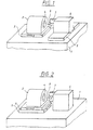
- the processing machine is built on a rigid machine bed 1.
- the spindle 2 is mounted on a slide 3 which is movable in the Z-axis.
- the spindle 2 receives the blank, not shown here, in a workpiece holder 4.
- the Carriage 3 is brought into a suitable position for presetting and then for the duration of processing clamped.
- the tool drive is located on a further carriage 5 which can be moved in the X direction 6, which is realized by a linear motor.
- the rotor 7 of the tool drive 6 carries the turning tool 8.
- Fig. 2 shows a variant of the processing machine, in which not the tool drive 6, but the spindle 2 is mounted on a carriage 5 which can be moved in the X direction is.
- the electrodynamic linear motor provides a possible tool drive accordingly Fig. 3 represents.
- the linear motor consists of a rotor 7, the permanent magnet 9 is equipped and the stator coil system 10. To achieve a low-friction
- the rotor 7 is mounted horizontally and vertically in movement in air bearings 11.
- the runner 7 carries a measuring system 12 for determining the position.
- the dynamic mass balance causes reaction forces caused by the necessary rapid movement of the turning tool 8, balanced and so any Accidental movement of the turning tool avoided, which results in the high surface quality of the processed lens and the accuracy of its optical geometry is made possible.
- FIG. 5 An analog device with hydraulically or pneumatically operating drives shows Fig. 5.
- the runners are realized by pistons 14 running in opposite directions.
- mass balancing can be achieved by applying force to a large mass be effected.
- the machine bed 1 as shown in Fig. 2, as large mass executed.
- the mass is dimensioned so that its resulting movement has an amplitude of less than 0.005 mm.
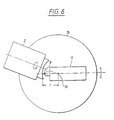
- Fig. 6 shows a machine structure in which instead of a carriage movement in the X direction a pivoting movement of the blank is provided.
- the spindle 2 is closed this purpose stored on a turntable 15.
- the pivot center 16 is located itself on the Z axis.
- the swiveling movement must have a suitable radius r be that can be chosen so that the additional, the pivoting movement superimposed movement of the turning tool 8 in the direction of the Z axis a minimum becomes.
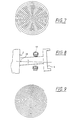
- Fig. 7 Mastery of central singularity is shown in Fig. 7.
- the blank becomes minor in two differing eccentric positions rotated, not to is turned to the spindle axis.
- the illustration shows the off-center positions shown schematically exaggerated.
- the broken line in Fig. 7 is not executed, the area not processed is then covered by the other position.
- the workpiece holder 4 of the spindle 2 can be pivoted slightly for this purpose listed.
- magnetic force caused by switchable electromagnets 17, as shown in FIG. 8, the displacement of the workpiece holder 4 in two different positions up and down by rotating around a pivot point 18 can be achieved.
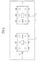
- Fig. 10 shows a variant of a processing machine in which the dynamic mass balance is exploited to simultaneously the second side of the To edit blanks.
- the spindle 2 is supported on a slide 5.
- the workpiece holder 4 is designed so that the blank from both sides can be edited.
- Tool drives 6, 13 are located on both sides of the spindle 2 provided that work in opposite directions. So the desired optical Effect equally distributed on both sides of the ophthalmic lens.
- FIG. 11 shows a block diagram of a control circuit for control and regulation the movements of the spindle 2 and the turning tool 8. It is with a digital controller e.g. worked a signal processor that optimal adjustment allowed to the controlled system. Structure and parameter optimization can function as the workpiece geometry. All quantities describing the system status (mechanical system, tachometers, position measuring systems) are fed to the digital controller. The slow movement in the X direction can also be operated by the controller become. This controlled system is not shown in FIG. 11. Considering of the setpoint, the power amplifiers for the motors are controlled. The required Dynamic range of the amplifier should be 100dB. For modulating fine A corresponding bandwidth must be provided for structures.
- the target data for the movements can be created before processing and stored in a memory. Preferably, however, the target data with the function describing the area Z (r, phi) calculated online.
- Optical surfaces are optically effective Surfaces of lenses, mirrors or other optical components that are through their behavior when transmitting or reflecting electromagnetic radiation distinguish (especially in the infrared, visible and ultraviolet spectral range).
Claims (27)
- Machine d'usinage pour la fabrication de surfaces optiques, en particulier de lentilles ophtalmiques et de coques de moulage pour la fabrication de lentilles ophtalmiques, en particulier de lentilles en plastique, comprenant une broche montée sur un banc de machine rigide (1), sur laquelle une ébauche pour un traitement de surface optique ou une ébauche d'une coque de moulage peut être maintenue, et un outil de tournage (8) déplaçable vers et depuis l'ébauche, l'outil de tournage (8) ou la broche (2) étant déplaçable perpendiculairement à la direction de l'axe de la broche (l'axe des X),
caractérisée en ce que
la commande (6) de l'outil de tournage (8) est réalisée dans la direction de l'axe des Z par un moteur linéaire à avance par incréments et en ce que pour le refroidissement de la ou des bobines du ou des moteurs linéaires, on utilise une réfrigération par effet de Peltier. - Machine d'usinage selon la revendication 1, caractérisée en ce qu'un refroidissement à eau est associé à la réfrigération par effet de Peltier.
- Machine d'usinage selon la revendication 1 ou 2, caractérisée en ce que la force de réaction causée par l'accélération de la commande linéaire (6) est équilibrée dynamiquement par une deuxième commande linéaire (13), qui est colinéaire à la première commande linéaire (6) et dont le logement ou le stator est accouplé mécaniquement au logement ou au stator de la première commande linéaire (6) par le biais du banc de la machine (1), et qui est commandée dans la direction opposée à la première commande linéaire (6).
- Machine d'usinage selon la revendication 1 ou 2, caractérisée en ce que la force de réaction causée par l'accélération de la commande linéaire (6) est équilibrée dynamiquement par l'introduction d'une force dans la masse du banc de la machine (1).
- Machine d'usinage selon la revendication 4, caractérisée en ce que le chariot (5) pour le mouvement suivant l'axe des X est monté sous la broche (2) et porte la broche (2).
- Machine d'usinage selon l'une quelconque des revendications 1 à 5,
caractérisée en ce que la commande linéaire (6, 13) est un moteur hydraulique. - Machine d'usinage selon l'une quelconque des revendications 1 à 5,
caractérisée en ce que la commande linéaire (6, 13) est un moteur linéaire électrodynamique. - Machine d'usinage selon l'une quelconque des revendications 1 à 7,
caractérisée en ce que le curseur du moteur linéaire est monté sur paliers à air. - Machine d'usinage selon l'une quelconque des revendications 1 à 7,
caractérisée en ce que le curseur du moteur linéaire est monté sur paliers au moyen d'air et de paliers magnétiques de support. - Machine d'usinage selon l'une quelconque des revendications 1 à 7,
caractérisée en ce que le curseur du moteur linéaire est monté sur paliers hydrauliques. - Machine d'usinage selon l'une quelconque des revendications 1 à 10, caractérisée en ce que des échelles balayées opto-électroniquement servent de système de mesure pour le mouvement linéaire de l'outil de tournage (8).
- Machine d'usinage selon l'une quelconque des revendications 1 à 10, caractérisée en ce que des interféromètres laser servent de système de mesure pour le mouvement linéaire de l'outil de tournage (8).
- Machine d'usinage selon l'une quelconque des revendications 1 à 12, caractérisée en ce qu'un encodeur opto-électronique sert de système de mesure pour le mouvement de rotation de l'ébauche.
- Machine d'usinage selon l'une quelconque des revendications 1 à 12, caractérisée en ce qu'un tachymètre sert de système de mesure pour le mouvement de rotation de l'ébauche.
- Machine d'usinage selon l'une quelconque des revendications 1 à 14, caractérisée en ce que le mouvement dans la direction de l'axe des X est réalisé en ce que la broche (2) est montée de manière à pouvoir pivoter autour d'un centre (16) placé sur l'axe des Z.
- Machine d'usinage selon l'une quelconque des revendications 1 à 14, caractérisée en ce que le chariot (5) déplaçable suivant l'axe des Z et portant l'outil de tournage (8) est monté de manière à pouvoir pivoter autour d'un centre placé sur l'axe des Z.
- Machine d'usinage selon l'une quelconque des revendications 1 à 16, caractérisée en ce que la broche (2) est montée coaxialement à l'ébauche, des deux côtés de l'ébauche, une commande linéaire respective (6, 13) est montée, la deuxième commande linéaire (13) présente un outil de tournage supplémentaire et un système de mesure pour la détermination de la position de cet outil de tournage et le chariot (5) pour le mouvement de l'ébauche suivant l'axe des X est monté sous la broche (2) et porte celle-ci.
- Machine d'usinage selon la revendication 17, caractérisée en ce qu'un équilibrage dynamique supplémentaire des masses est réalisé par le fait qu'une troisième commande linéaire est disposée de manière colinéaire aux deux commandes linéaires (6, 13), dont le logement ou le stator est accouplé mécaniquement aux logements ou aux stators des deux autres commandes linéaires (6, 13) par le biais du banc de la machine (1), et est commandée dans la direction opposée à la direction de la force résultant du mouvement des première et deuxième commandes linéaires.
- Machine d'usinage selon l'une quelconque des revendications 1 à 18, caractérisée en ce que pour la commande de toutes les commandes et pour le traitement des données de position de l'ébauche et du ou des outils de tournage, on utilise au moins un régulateur numérique.
- Procédé de fabrication de surfaces optiques, en particulier de lentilles ophtalmiques et de coques de moulage pour la fabrication de lentilles ophtalmiques, en particulier de lentilles en plastique asphériques, dans lequel une ébauche pour un traitement de surface optique ou une ébauche pour une coque de moulage pour la fabrication de surfaces optiques est maintenue sur la fixation de pièce d'un axe de broche (axe des Z) d'une machine d'usinage et est tournée directement à sa forme finale au moyen d'un outil de tournage, qui peut exercer un mouvement relatif par rapport à l'ébauche, où l'outil de tournage peut se déplacer transversalement à la direction de mouvement de l'outil (axe des X) et au cours de chaque rotation de la broche, des avances par incréments de cet outil de tournage sont effectuées vers et depuis l'ébauche (axe des Z) en fonction de données de surface prédéfinies ou calculées en ligne,
caractérisé en ce que
la machine d'usinage selon l'une quelconque des revendications 1 à 19 est utilisée. - Procédé selon la revendication 20, caractérisé en ce que l'équilibrage dynamique des masses est réalisé totalement ou partiellement par un deuxième outil de tournage, qui est déplaçable au moyen d'une commande propre dans la direction de l'axe des Z, et agit sur le deuxième côté de l'ébauche ou sur une deuxième ébauche.
- Procédé selon la revendication 20 ou 21, caractérisé en ce que l'ébauche, après le tournage, est rendue apte à l'utilisation par polissage.
- Procédé selon l'une quelconque des revendications 20 à 22,
caractérisé en ce que l'ébauche, après le tournage, est rendue apte à l'utilisation par trempage dans du vernis. - Procédé selon l'une quelconque des revendications 20 à 23, caractérisé en ce que les positions de l'outil de tournage et de l'ébauche sont détectées de manière opto-électronique.
- Procédé selon l'une quelconque des revendications 20 à 24, caractérisé en ce que toutes les grandeurs décrivant l'état du système sont acheminées à un circuit de réglage numérique et que le réglage s'effectue en tenant compte de la géométrie calculée de la surface optique.
- Procédé selon l'une quelconque des revendications 20 à 25, caractérisé en ce que la position de l'outil de tournage et de la broche ou de l'ébauche sont mesurées en continu et comparées aux données que l'on veut obtenir, et des données de correction sont déterminées à partir de celles-ci pour l'avance de l'outil de tournage.
- Procédé selon l'une quelconque des revendications 20 à 26, caractérisé en ce que la position du mouvement de l'outil dans la direction de l'axe des Z est déterminée avec une précision d'au moins 0,0005 mm.
Applications Claiming Priority (3)
| Application Number | Priority Date | Filing Date | Title |
|---|---|---|---|
| DE19538274 | 1995-10-14 | ||
| DE19538274 | 1995-10-14 | ||
| PCT/DE1996/001947 WO1997013603A2 (fr) | 1995-10-14 | 1996-10-11 | Procede de fabrication de surfaces optiques et machine a usiner propre a mettre en oeuvre ce procede |
Publications (2)
| Publication Number | Publication Date |
|---|---|
| EP0854769A2 EP0854769A2 (fr) | 1998-07-29 |
| EP0854769B1 true EP0854769B1 (fr) | 2002-02-27 |
Family
ID=7774848
Family Applications (1)
| Application Number | Title | Priority Date | Filing Date |
|---|---|---|---|
| EP96946356A Expired - Lifetime EP0854769B1 (fr) | 1995-10-14 | 1996-10-11 | Procede de fabrication de surfaces optiques et machine a usiner propre a mettre en oeuvre ce procede |
Country Status (7)
| Country | Link |
|---|---|
| US (1) | US6523443B1 (fr) |
| EP (1) | EP0854769B1 (fr) |
| JP (1) | JP3938213B2 (fr) |
| AT (1) | ATE213683T1 (fr) |
| DE (1) | DE19680863B4 (fr) |
| ES (1) | ES2173343T3 (fr) |
| WO (1) | WO1997013603A2 (fr) |
Cited By (4)
| Publication number | Priority date | Publication date | Assignee | Title |
|---|---|---|---|---|
| DE102004019931A1 (de) * | 2004-04-21 | 2005-11-10 | Schneider Gmbh + Co. Kg | Korrekturverfahren für Zerspanungsmaschinen |
| EP1719573A1 (fr) * | 2005-05-06 | 2006-11-08 | Satisloh GmbH | Tour avec corps monolithique en béton polymère |
| CN101687302A (zh) * | 2007-07-09 | 2010-03-31 | 卡尔蔡司Smt股份公司 | 测量光学表面从目标形状偏差的方法 |
| WO2013117327A3 (fr) * | 2012-02-06 | 2013-10-03 | Schneider Gmbh & Co. Kg | Entrainement lineaire |
Families Citing this family (35)
| Publication number | Priority date | Publication date | Assignee | Title |
|---|---|---|---|---|
| US6523443B1 (en) * | 1995-10-14 | 2003-02-25 | Carl-Zeiss-Stiftung, Heidenheim/Brenz | Process for manufacturing optical surfaces and shaping machine for carrying out this process |
| DE19653233A1 (de) * | 1996-12-20 | 1998-07-02 | Schneider Gmbh & Co Kg | Hochgeschwindigkeits-Drehmaschine zum Herstellen optisch wirksamer Oberflächen |
| DE19701312A1 (de) * | 1997-01-16 | 1998-07-23 | Zeiss Carl Fa | Brillenglas mit sphärischer Vorderseite und multifokaler Rückseite, sowie Verfahren zu seiner Herstellung |
| SE514666C2 (sv) * | 1999-07-05 | 2001-04-02 | Sandvik Ab | Metod för fixering av skär vid PVD-beläggning |
| CA2313830A1 (fr) * | 2000-07-13 | 2002-01-13 | Micro Optics Design Corporation | Tour au diamant a pointe unique dote d'un systeme antivibratoire |
| DE10114239A1 (de) * | 2001-03-22 | 2002-10-02 | Loh Optikmaschinen Ag | Vorrichtung zur Randbearbeitung von optischen Linsen |
| DE10143848C2 (de) * | 2001-09-06 | 2003-10-02 | Loh Optikmaschinen Ag | Verfahren und Vorrichtung zur Flächenbearbeitung von Werkstücken aus nicht-sprödharten Materialien in der Optikfertigung sowie Werkzeug dafür |
| US6621241B2 (en) * | 2001-12-20 | 2003-09-16 | Dac International, Inc. | System and method for reducing oscillating tool-induced reaction forces |
| US7765905B2 (en) * | 2002-05-29 | 2010-08-03 | Massachusetts Institute Of Technology | Magnetic micropositioner and method of providing the same |
| US7574947B2 (en) * | 2002-05-29 | 2009-08-18 | Massachusetts Institute Of Technology | Rotary fast tool servo system and methods |
| US7437980B2 (en) * | 2002-05-29 | 2008-10-21 | Massachusetts Institute Of Technology | Flux-biased electromagnetic fast tool servo systems and methods |
| US7275468B2 (en) * | 2002-05-29 | 2007-10-02 | Massachusetts Institute Of Technology | Rotary fast tool servo system and methods |
| DE10250856A1 (de) | 2002-10-25 | 2004-05-13 | Carl Zeiss | Verfahren und Vorrichtung zum Herstellen von optischen Gläsern |
| WO2005043266A2 (fr) * | 2003-10-31 | 2005-05-12 | Massachusetts Institute Of Technology | Systemes et procedes de positionnement rapide a reluctance variable |
| DE102004037454A1 (de) * | 2004-08-02 | 2006-02-23 | Carl Zeiss Ag | Verfahren zur Bearbeitung von Oberflächen von Werkstücken |
| DE102004049951A1 (de) | 2004-10-13 | 2006-04-20 | Schneider Gmbh + Co. Kg | Hochdynamische Linsenbearbeitungsmaschine |
| US7198436B2 (en) * | 2004-10-14 | 2007-04-03 | National Optronics, Inc. | Multi-blade router tool, edger with multi-blade router tool, and method of edging eyeglass lenses |
| DE102005021640B4 (de) * | 2005-05-06 | 2007-08-09 | Satisloh Gmbh | Maschine zur Bearbeitung von optischen Werkstücken, insbesondere von Kunststoff-Brillengläsern |
| WO2007122961A1 (fr) * | 2006-04-21 | 2007-11-01 | Hoya Corporation | Dispositif de traitement de lentilles et procede de traitement de lentilles |
| DE102006026524A1 (de) * | 2006-06-06 | 2007-12-13 | Satisloh Ag | Maschine zur Bearbeitung von optischen Werkstücken, insbesondere von Kunststoff-Brillengläsern |
| EP1916060B1 (fr) * | 2006-10-26 | 2009-05-06 | Satisloh AG | Machine destinée au traitement de pièces optiques, en particulier de verres solaires en plastique |
| DE102007031703A1 (de) * | 2007-07-06 | 2009-01-08 | Satisloh Gmbh | Maschine zur Bearbeitung von optischen Werkstücken, insbesondere von Kunststoff-Brillengläsern |
| CN102209941B (zh) * | 2008-09-18 | 2015-05-06 | Flir系统贸易比利时有限公司 | 用于对材料进行机械加工的系统和方法 |
| EP2429774A2 (fr) * | 2009-01-13 | 2012-03-21 | Camotion, Inc. | Machines-outils ayant un dispositif robotique non rigide utilisant un raidissement inertiel |
| DE102009011194A1 (de) * | 2009-03-04 | 2010-09-09 | Schneider Gmbh & Co. Kg | Drehmaschine zum Herstellen von Brillengläsern aus Kunststoff |
| EP2684643A3 (fr) * | 2012-05-22 | 2014-04-16 | Schneider GmbH & Co. KG | Dispositif et procédé de traitement d'une pièce usinée optique |
| DE102012014399A1 (de) | 2012-07-20 | 2014-05-15 | Carl Zeiss Vision International Gmbh | Vorrichtung zum Ermitteln und Ausgeben eines für einen Brillenträger geeigneten Brillenlinsentyp |
| CN102773503B (zh) * | 2012-08-21 | 2014-11-05 | 上海现代先进超精密制造中心有限公司 | 单点金刚石车床和异形工件的加工方法 |
| CN103878534B (zh) * | 2012-12-19 | 2016-05-11 | 鸿准精密模具(昆山)有限公司 | 金属件加工方法 |
| CN103878591B (zh) * | 2012-12-19 | 2016-12-28 | 鸿准精密模具(昆山)有限公司 | 金属件加工方法 |
| DE102013218136B3 (de) | 2013-09-11 | 2015-02-12 | Carl Zeiss Vision International Gmbh | Brillenglas-Halb- oder -Fertigfabrikat, Verfahren zu dessen Herstellung und Verfahren zum Beschichten eines Brillenglas-Halb- oder -Fertigfabrikats |
| DE102013020597B3 (de) * | 2013-12-13 | 2014-10-30 | FMB Maschinenbaugesellschaft | Auswuchtvorrichtung für ein Stangenlademagazin |
| US9618774B2 (en) | 2014-02-10 | 2017-04-11 | Shamir Optical Industry Ltd. | Quasi progressive lenses for eyewear |
| DE102014213393B4 (de) | 2014-07-10 | 2016-12-29 | Carl Zeiss Vision International Gmbh | Satz von Brillenglashalbfabrikaten, computerimplementiertes Verfahren zu dessen Auslegung, Computerprogramm, computerlesbares Speichermedium, Verfahren und Vorrichtung zur Herstellung von Brillengläsern sowie Verwendung eines Satzes von Brillenglashalbfab |
| EP3542956A1 (fr) | 2018-03-23 | 2019-09-25 | Carl Zeiss Vision International GmbH | Procédé de fabrication de lentilles de lunettes selon une ordonnance |
Family Cites Families (20)
| Publication number | Priority date | Publication date | Assignee | Title |
|---|---|---|---|---|
| US543504A (en) * | 1895-07-30 | Machine for cutting dough | ||
| CH566186A5 (fr) * | 1973-09-13 | 1975-09-15 | Fontainemelon Fabrique D Horlo | |
| US4254065A (en) * | 1979-04-04 | 1981-03-03 | Ratkowski Donald J | Injection molding of contact lenses |
| US4455901A (en) * | 1981-10-09 | 1984-06-26 | Bausch & Lomb Incorporated | Apparatus for controlling lathed contact lens thickness |
| JPS59110362A (ja) * | 1982-12-15 | 1984-06-26 | Amada Co Ltd | リニアモ−タ |
| US4711035A (en) * | 1986-08-04 | 1987-12-08 | Gerber Scientific Products, Inc. | Method and apparatus for making a pattern for a lens opening in an eyeglass frame |
| US4839545A (en) * | 1987-10-16 | 1989-06-13 | Anwar Chitayat | Cooling system for linear motor |
| DE3911986A1 (de) * | 1989-04-12 | 1990-10-18 | Benzinger Carl Gmbh & Co | Verfahren und vorrichtung zur formgebenden bearbeitung von werkstuecken |
| FR2653949B1 (fr) * | 1989-10-30 | 1992-02-07 | Celduc Const Elect Centre | Dispositif de refroidissement pour inducteur de moteur lineaire. |
| DE59100077D1 (de) * | 1990-01-24 | 1993-05-19 | Ciba Geigy Ag | Vorrichtung zum herstellen einer kontaktlinse mit insbesondere asphaerischer vorder- und/oder rueckflaeche. |
| US5217335A (en) * | 1990-04-24 | 1993-06-08 | National Optronics, Inc. | Plastic lens generator and method |
| JP3026824B2 (ja) * | 1990-07-31 | 2000-03-27 | 株式会社メニコン | 非球面レンズの製造装置 |
| DE4125707C2 (de) * | 1991-08-02 | 1994-08-04 | Hecht Gmbh Kontaktlinsen | Vorrichtung zum Herstellen einer Bifokal-Contactlinse und damit hergestellte Contactlinse |
| US5485771A (en) * | 1991-09-27 | 1996-01-23 | Coburn Optical Industries, Inc. | Apparatus for generating ophthalmic products from blanks and a method of operating same |
| US5320006A (en) * | 1991-09-27 | 1994-06-14 | Coburn Optical Industries, Inc. | Methods and apparatus for producing ophthalmic lenses |
| JP2995128B2 (ja) * | 1993-02-08 | 1999-12-27 | 株式会社メニコン | トーリックレンズの切削加工用保持装置 |
| DE69314335T2 (de) * | 1993-09-06 | 1998-05-07 | Voumard Machines Co Sa | Werkverfahren und Vorrichtung, insbesondere Schleifmaschine mit Abgleichschwingbewegung |
| US5794498A (en) * | 1994-10-19 | 1998-08-18 | Taylor Hobson Limited | In-situ method and apparatus for blocking lenses |
| US5724120A (en) * | 1995-10-02 | 1998-03-03 | Svochak; Jan B. | Multifocal contact lens and method and apparatus for making the same |
| US6523443B1 (en) * | 1995-10-14 | 2003-02-25 | Carl-Zeiss-Stiftung, Heidenheim/Brenz | Process for manufacturing optical surfaces and shaping machine for carrying out this process |
-
1996
- 1996-10-11 US US09/051,629 patent/US6523443B1/en not_active Expired - Lifetime
- 1996-10-11 WO PCT/DE1996/001947 patent/WO1997013603A2/fr active IP Right Grant
- 1996-10-11 ES ES96946356T patent/ES2173343T3/es not_active Expired - Lifetime
- 1996-10-11 JP JP51463397A patent/JP3938213B2/ja not_active Expired - Lifetime
- 1996-10-11 AT AT96946356T patent/ATE213683T1/de not_active IP Right Cessation
- 1996-10-11 DE DE19680863T patent/DE19680863B4/de not_active Expired - Lifetime
- 1996-10-11 EP EP96946356A patent/EP0854769B1/fr not_active Expired - Lifetime
Cited By (8)
| Publication number | Priority date | Publication date | Assignee | Title |
|---|---|---|---|---|
| DE102004019931A1 (de) * | 2004-04-21 | 2005-11-10 | Schneider Gmbh + Co. Kg | Korrekturverfahren für Zerspanungsmaschinen |
| DE102004019931B4 (de) * | 2004-04-21 | 2012-01-05 | Schneider Gmbh & Co. Kg | Korrekturverfahren für Zerspanungsmaschinen |
| EP1719573A1 (fr) * | 2005-05-06 | 2006-11-08 | Satisloh GmbH | Tour avec corps monolithique en béton polymère |
| DE102005021638A1 (de) * | 2005-05-06 | 2006-11-16 | Satisloh Gmbh | Drehmaschine zur Bearbeitung von optischen Werkstücken |
| DE102005021638B4 (de) * | 2005-05-06 | 2007-03-29 | Satisloh Gmbh | Drehmaschine zur Bearbeitung von optischen Werkstücken |
| CN101687302A (zh) * | 2007-07-09 | 2010-03-31 | 卡尔蔡司Smt股份公司 | 测量光学表面从目标形状偏差的方法 |
| CN101687302B (zh) * | 2007-07-09 | 2013-06-05 | 卡尔蔡司Smt有限责任公司 | 非球面、其幅值的布置及包含其的投射物镜 |
| WO2013117327A3 (fr) * | 2012-02-06 | 2013-10-03 | Schneider Gmbh & Co. Kg | Entrainement lineaire |
Also Published As
| Publication number | Publication date |
|---|---|
| ATE213683T1 (de) | 2002-03-15 |
| DE19680863B4 (de) | 2013-06-13 |
| JP4572187B2 (ja) | 2010-10-27 |
| JP2007050509A (ja) | 2007-03-01 |
| JP2000515074A (ja) | 2000-11-14 |
| ES2173343T3 (es) | 2002-10-16 |
| WO1997013603A2 (fr) | 1997-04-17 |
| DE19680863D2 (de) | 1999-03-11 |
| WO1997013603A3 (fr) | 1997-06-12 |
| US6523443B1 (en) | 2003-02-25 |
| EP0854769A2 (fr) | 1998-07-29 |
| JP3938213B2 (ja) | 2007-06-27 |
Similar Documents
| Publication | Publication Date | Title |
|---|---|---|
| EP0854769B1 (fr) | Procede de fabrication de surfaces optiques et machine a usiner propre a mettre en oeuvre ce procede | |
| WO1997013603A9 (fr) | Procede de fabrication de surfaces optiques et machine a usiner propre a mettre en oeuvre ce procede | |
| EP0849038B1 (fr) | Tour à grande vitesse pour la fabrication de surfaces optiques actives | |
| DE10029967B4 (de) | Vorrichtung zur Bearbeitung von optischen Werkstücken | |
| EP1764185B1 (fr) | Dispositif et méthode pour la production de micro-structures | |
| EP3463746B1 (fr) | Machine pour le traitement des surfaces à effet optique | |
| US3881378A (en) | Machine for producing aspherical surfaces | |
| EP4190488A1 (fr) | Unité d'usinage, en particulier pour une machine de centrage de pièces telles que des lentilles optiques | |
| EP0685298B2 (fr) | Procédé et dispositif pour fabriquer des lentilles asphériques | |
| EP2684643A2 (fr) | Dispositif et procédé de traitement dýune pièce usinée optique | |
| DE602004000175T2 (de) | Schneideverfahren mit hoher Geschwindigkeit zur Herstellung einer gekrümmten Werkstückfläche | |
| DE19751750B4 (de) | Verfahren und Vorrichtung zum Herstellen von polierbaren, optischen Linsen aus Linsenrohlingen | |
| DE19846260A1 (de) | Vorrichtung zum Bearbeiten optischer Linsen durch Schleifen und Polieren | |
| EP0159383A1 (fr) | Machine pour meuler les surfaces toriques de lentilles optiques | |
| DE102004020990B4 (de) | Vorrichtung und Verfahren zur Erzeugung von Mikrostrukturen | |
| EP0440578A1 (fr) | Dispositif pour usiner des planes courbes dans un moule de lentilles optiques et ophtalmiques | |
| DE102007050470A1 (de) | Verfahren zum Herstellen von optisch aktiven Oberflächen durch Polieren von vorgeschliffenen Linsen und eine Vorrichtung zur Durchführung des Verfahrens | |
| EP0999004A2 (fr) | Mandrin pour une machine-outil | |
| JP2002542048A (ja) | 眼球用レンズ上に究極の表面を生成する方法および装置 | |
| US3704554A (en) | Lens processing machine with movable workpiece spindle | |
| EP0384907B1 (fr) | Procédé et dispositif pour la production d'un objet à partir d'une pièce d'oeuvre | |
| DE2659489A1 (de) | Maschine zum fraesen asphaerischer, insbesondere torischer flaechen von optischen glaesern, beispielsweise brillenglaeser | |
| CA2220371C (fr) | Procede et dispositif de finissage de verres ophtalmiques | |
| DE102021133373A1 (de) | BEARBEITEN VON AUßERAXIAL ANGEORDNETEN OPTISCHEN WERKSTÜCKEN | |
| DE19737215A1 (de) | Werkzeugkomibation bestehend aus Spannwerkzeug für Linsen und Abrichtwerkzeug für Polierwerkzeuge |
Legal Events
| Date | Code | Title | Description |
|---|---|---|---|
| PUAI | Public reference made under article 153(3) epc to a published international application that has entered the european phase |
Free format text: ORIGINAL CODE: 0009012 |
|
| 17P | Request for examination filed |
Effective date: 19980512 |
|
| AK | Designated contracting states |
Kind code of ref document: A2 Designated state(s): AT CH ES FR GB LI NL |
|
| 17Q | First examination report despatched |
Effective date: 19991130 |
|
| GRAG | Despatch of communication of intention to grant |
Free format text: ORIGINAL CODE: EPIDOS AGRA |
|
| GRAG | Despatch of communication of intention to grant |
Free format text: ORIGINAL CODE: EPIDOS AGRA |
|
| GRAH | Despatch of communication of intention to grant a patent |
Free format text: ORIGINAL CODE: EPIDOS IGRA |
|
| GRAH | Despatch of communication of intention to grant a patent |
Free format text: ORIGINAL CODE: EPIDOS IGRA |
|
| REG | Reference to a national code |
Ref country code: GB Ref legal event code: IF02 |
|
| RAP1 | Party data changed (applicant data changed or rights of an application transferred) |
Owner name: CARL ZEISS |
|
| GRAA | (expected) grant |
Free format text: ORIGINAL CODE: 0009210 |
|
| AK | Designated contracting states |
Kind code of ref document: B1 Designated state(s): AT CH ES FR GB LI NL |
|
| REF | Corresponds to: |
Ref document number: 213683 Country of ref document: AT Date of ref document: 20020315 Kind code of ref document: T |
|
| REG | Reference to a national code |
Ref country code: CH Ref legal event code: EP |
|
| GBT | Gb: translation of ep patent filed (gb section 77(6)(a)/1977) |
Effective date: 20020503 |
|
| REG | Reference to a national code |
Ref country code: CH Ref legal event code: NV Representative=s name: E. BLUM & CO. PATENTANWAELTE |
|
| ET | Fr: translation filed | ||
| REG | Reference to a national code |
Ref country code: ES Ref legal event code: FG2A Ref document number: 2173343 Country of ref document: ES Kind code of ref document: T3 |
|
| PLBE | No opposition filed within time limit |
Free format text: ORIGINAL CODE: 0009261 |
|
| STAA | Information on the status of an ep patent application or granted ep patent |
Free format text: STATUS: NO OPPOSITION FILED WITHIN TIME LIMIT |
|
| 26N | No opposition filed |
Effective date: 20021128 |
|
| PGFP | Annual fee paid to national office [announced via postgrant information from national office to epo] |
Ref country code: AT Payment date: 20061011 Year of fee payment: 11 |
|
| PGFP | Annual fee paid to national office [announced via postgrant information from national office to epo] |
Ref country code: NL Payment date: 20061016 Year of fee payment: 11 |
|
| REG | Reference to a national code |
Ref country code: CH Ref legal event code: PFA Owner name: CARL ZEISS Free format text: CARL ZEISS# #73446 OBERKOCHEN (DE) -TRANSFER TO- CARL ZEISS# #73446 OBERKOCHEN (DE) |
|
| NLV4 | Nl: lapsed or anulled due to non-payment of the annual fee |
Effective date: 20080501 |
|
| PG25 | Lapsed in a contracting state [announced via postgrant information from national office to epo] |
Ref country code: AT Free format text: LAPSE BECAUSE OF NON-PAYMENT OF DUE FEES Effective date: 20071011 |
|
| PG25 | Lapsed in a contracting state [announced via postgrant information from national office to epo] |
Ref country code: NL Free format text: LAPSE BECAUSE OF NON-PAYMENT OF DUE FEES Effective date: 20080501 |
|
| REG | Reference to a national code |
Ref country code: FR Ref legal event code: PLFP Year of fee payment: 20 |
|
| PGFP | Annual fee paid to national office [announced via postgrant information from national office to epo] |
Ref country code: CH Payment date: 20151021 Year of fee payment: 20 Ref country code: GB Payment date: 20151021 Year of fee payment: 20 |
|
| PGFP | Annual fee paid to national office [announced via postgrant information from national office to epo] |
Ref country code: ES Payment date: 20151028 Year of fee payment: 20 Ref country code: FR Payment date: 20151023 Year of fee payment: 20 |
|
| REG | Reference to a national code |
Ref country code: CH Ref legal event code: PL |
|
| REG | Reference to a national code |
Ref country code: GB Ref legal event code: PE20 Expiry date: 20161010 |
|
| REG | Reference to a national code |
Ref country code: ES Ref legal event code: FD2A Effective date: 20170126 |
|
| PG25 | Lapsed in a contracting state [announced via postgrant information from national office to epo] |
Ref country code: GB Free format text: LAPSE BECAUSE OF EXPIRATION OF PROTECTION Effective date: 20161010 |
|
| PG25 | Lapsed in a contracting state [announced via postgrant information from national office to epo] |
Ref country code: ES Free format text: LAPSE BECAUSE OF EXPIRATION OF PROTECTION Effective date: 20161012 |