EP0854769B1 - Process for manufacturing optical surfaces and shaping machine for carrying out this process - Google Patents
Process for manufacturing optical surfaces and shaping machine for carrying out this process Download PDFInfo
- Publication number
- EP0854769B1 EP0854769B1 EP96946356A EP96946356A EP0854769B1 EP 0854769 B1 EP0854769 B1 EP 0854769B1 EP 96946356 A EP96946356 A EP 96946356A EP 96946356 A EP96946356 A EP 96946356A EP 0854769 B1 EP0854769 B1 EP 0854769B1
- Authority
- EP
- European Patent Office
- Prior art keywords
- blank
- processing machine
- machine according
- turning tool
- axis
- Prior art date
- Legal status (The legal status is an assumption and is not a legal conclusion. Google has not performed a legal analysis and makes no representation as to the accuracy of the status listed.)
- Expired - Lifetime
Links
Images


Classifications
-
- B—PERFORMING OPERATIONS; TRANSPORTING
- B24—GRINDING; POLISHING
- B24B—MACHINES, DEVICES, OR PROCESSES FOR GRINDING OR POLISHING; DRESSING OR CONDITIONING OF ABRADING SURFACES; FEEDING OF GRINDING, POLISHING, OR LAPPING AGENTS
- B24B13/00—Machines or devices designed for grinding or polishing optical surfaces on lenses or surfaces of similar shape on other work; Accessories therefor
- B24B13/06—Machines or devices designed for grinding or polishing optical surfaces on lenses or surfaces of similar shape on other work; Accessories therefor grinding of lenses, the tool or work being controlled by information-carrying means, e.g. patterns, punched tapes, magnetic tapes
-
- B—PERFORMING OPERATIONS; TRANSPORTING
- B23—MACHINE TOOLS; METAL-WORKING NOT OTHERWISE PROVIDED FOR
- B23Q—DETAILS, COMPONENTS, OR ACCESSORIES FOR MACHINE TOOLS, e.g. ARRANGEMENTS FOR COPYING OR CONTROLLING; MACHINE TOOLS IN GENERAL CHARACTERISED BY THE CONSTRUCTION OF PARTICULAR DETAILS OR COMPONENTS; COMBINATIONS OR ASSOCIATIONS OF METAL-WORKING MACHINES, NOT DIRECTED TO A PARTICULAR RESULT
- B23Q11/00—Accessories fitted to machine tools for keeping tools or parts of the machine in good working condition or for cooling work; Safety devices specially combined with or arranged in, or specially adapted for use in connection with, machine tools
- B23Q11/0032—Arrangements for preventing or isolating vibrations in parts of the machine
-
- B—PERFORMING OPERATIONS; TRANSPORTING
- B24—GRINDING; POLISHING
- B24B—MACHINES, DEVICES, OR PROCESSES FOR GRINDING OR POLISHING; DRESSING OR CONDITIONING OF ABRADING SURFACES; FEEDING OF GRINDING, POLISHING, OR LAPPING AGENTS
- B24B13/00—Machines or devices designed for grinding or polishing optical surfaces on lenses or surfaces of similar shape on other work; Accessories therefor
-
- B—PERFORMING OPERATIONS; TRANSPORTING
- B23—MACHINE TOOLS; METAL-WORKING NOT OTHERWISE PROVIDED FOR
- B23Q—DETAILS, COMPONENTS, OR ACCESSORIES FOR MACHINE TOOLS, e.g. ARRANGEMENTS FOR COPYING OR CONTROLLING; MACHINE TOOLS IN GENERAL CHARACTERISED BY THE CONSTRUCTION OF PARTICULAR DETAILS OR COMPONENTS; COMBINATIONS OR ASSOCIATIONS OF METAL-WORKING MACHINES, NOT DIRECTED TO A PARTICULAR RESULT
- B23Q2230/00—Special operations in a machine tool
- B23Q2230/004—Using a cutting tool reciprocating at high speeds, e.g. "fast tool"
-
- Y—GENERAL TAGGING OF NEW TECHNOLOGICAL DEVELOPMENTS; GENERAL TAGGING OF CROSS-SECTIONAL TECHNOLOGIES SPANNING OVER SEVERAL SECTIONS OF THE IPC; TECHNICAL SUBJECTS COVERED BY FORMER USPC CROSS-REFERENCE ART COLLECTIONS [XRACs] AND DIGESTS
- Y10—TECHNICAL SUBJECTS COVERED BY FORMER USPC
- Y10T—TECHNICAL SUBJECTS COVERED BY FORMER US CLASSIFICATION
- Y10T82/00—Turning
- Y10T82/12—Radially moving rotating tool inside bore
- Y10T82/125—Tool simultaneously moving axially
-
- Y—GENERAL TAGGING OF NEW TECHNOLOGICAL DEVELOPMENTS; GENERAL TAGGING OF CROSS-SECTIONAL TECHNOLOGIES SPANNING OVER SEVERAL SECTIONS OF THE IPC; TECHNICAL SUBJECTS COVERED BY FORMER USPC CROSS-REFERENCE ART COLLECTIONS [XRACs] AND DIGESTS
- Y10—TECHNICAL SUBJECTS COVERED BY FORMER USPC
- Y10T—TECHNICAL SUBJECTS COVERED BY FORMER US CLASSIFICATION
- Y10T82/00—Turning
- Y10T82/14—Axial pattern
- Y10T82/141—Axial pattern having transverse tool and templet guide
- Y10T82/143—Axial pattern having transverse tool and templet guide having electrical actuator
-
- Y—GENERAL TAGGING OF NEW TECHNOLOGICAL DEVELOPMENTS; GENERAL TAGGING OF CROSS-SECTIONAL TECHNOLOGIES SPANNING OVER SEVERAL SECTIONS OF THE IPC; TECHNICAL SUBJECTS COVERED BY FORMER USPC CROSS-REFERENCE ART COLLECTIONS [XRACs] AND DIGESTS
- Y10—TECHNICAL SUBJECTS COVERED BY FORMER USPC
- Y10T—TECHNICAL SUBJECTS COVERED BY FORMER US CLASSIFICATION
- Y10T82/00—Turning
- Y10T82/25—Lathe
- Y10T82/2502—Lathe with program control
-
- Y—GENERAL TAGGING OF NEW TECHNOLOGICAL DEVELOPMENTS; GENERAL TAGGING OF CROSS-SECTIONAL TECHNOLOGIES SPANNING OVER SEVERAL SECTIONS OF THE IPC; TECHNICAL SUBJECTS COVERED BY FORMER USPC CROSS-REFERENCE ART COLLECTIONS [XRACs] AND DIGESTS
- Y10—TECHNICAL SUBJECTS COVERED BY FORMER USPC
- Y10T—TECHNICAL SUBJECTS COVERED BY FORMER US CLASSIFICATION
- Y10T82/00—Turning
- Y10T82/25—Lathe
- Y10T82/2531—Carriage feed
- Y10T82/2533—Control
Definitions
- the invention relates to a method for producing optical surfaces, especially of ophthalmic lenses and molded shells for the production of ophthalmic lenses (especially aspherical plastic lenses), as well as a Processing machine for performing the method.
- a device according to the preamble of claim 1 and a method according to the preamble of claim 20 are known from EP-A-0 439 425.
- Optical surfaces and especially ophthalmic lenses with complicated Geometry can now be made of silicate glass or plastic getting produced.
- silicate lenses they are made by grinding and subsequent Polishing made.
- Plastic lenses are made by casting in a previously made Negative form made.
- the negative forms, so-called molded shells, are made Silicate glass with the same method as in the production of ophthalmic lenses, also produced by grinding and polishing.
- a disadvantage of this procedure is that, in particular for the production of ophthalmic lenses all required geometric shapes are kept in stock have to.
- the invention has for its object to provide a device and a method, with what geometrically complex shaped optical surfaces and especially ophthalmic ones Lenses and molded shells for the production of ophthalmic lenses according to individual Data specification can be made directly in a single process step, whereby no or at least only slight reworking to complete the optical surfaces and in particular the ophthalmic lenses and molded shells for manufacturing ophthalmic lenses should be needed.
- a tool stylus can move so quickly by the method according to the invention be that those occurring in the circumferential direction, due to the aspherical shape Changes in height can be worked out from a plastic blank.
- the stylus can have a very small radius, which makes the intervention almost punctiform becomes.
- the stylus can also have a radius of several millimeters. It can be set with a monocrystalline diamond.
- the surface created is usually ready for use. May be necessary a little reworking to make it usable Polishing. The shape is completely determined by the turning process and by the polishing no longer changed.
- the surface can also be e.g. usable by dipping in paint be made.
- the process can also be used to manufacture molded shells ophthalmic lenses, e.g. made of metal or ceramic.
- polishing is only required to a very small extent.
- optical surfaces e.g. other lenses or mirrors with complicated, non-rotationally symmetrical Shape.
- this concerns the production of molded shells e.g. for the production of ophthalmic lenses. All markings can also be used in the molded shells later orientation of the lens and other signs can be attached.
- the turning tool performs a pivoting movement relative to the spindle.
- the blank can additionally pivoted when rotating around a center point lying on the Z axis become.
- the turning tool can also be rotated by one center point lying on the Z axis.
- the deflection of the lens material of the material does not require fast tool movements, you can do this Movement either by a slow Z movement or by a swivel movement replace, which is superimposed on the fast sterndrive.
- the fast Z movement must then be used to manufacture e.g. Progressive lenses only have a stroke of approx. 1 mm to have. This procedure has the particular advantage that the shape used area of the turning tool becomes smaller. Uneven wear on the The turning tool then has minor effects.
- a problem with every turning process is the singularity in the middle of the workpiece. It can therefore be provided in a preferred manner that the blank in two slightly off-axis positions deviating from the turning center.
- the blank is machined so that the respective turning center is just through the process is reached in the other position. So you don't turn up to Spindle axis.
- the rotary movement at the edge can be void. This can be avoided by, according to the invention, the path distances in the X direction varied. This then also requires a corresponding one for this feed drive Dynamics, e.g. by applying harmonic vibrations can. Dynamic mass balancing is also advantageous for this.
- Dynamic mass balance requires that a second movement be equal to one large mass must be executed with the opposite direction of movement. you can use this collinear motion to simultaneously move the front and back e.g. a plastic lens or a second ophthalmic lens or one to process the second molded shell for the production of ophthalmic lenses.
- a plastic lens or a second ophthalmic lens or one to process the second molded shell for the production of ophthalmic lenses Depending on The surface design and the blank can be used by simultaneously processing the Front and back brought about mass balancing of the two opposing fast ones Tools are sufficient to achieve the acceleration caused by the turning tools To absorb reaction force. If such compensation is not fully achieved, a third collinear mass balance may be required.
- the position of the tool movement in the Z direction should preferably be at least 0.0005mm can be determined exactly.
- Measuring systems with at least 0.0005mm resolution and the required length are z.
- B. available as opto-electronically scanned scales or laser interferometer.
- Optoelectronic rotary encoders are suitable for determining the position of the rotary movement.
- Tachometers for determining the current movement speeds are also available.
- all of the Parameters describing the system state can be fed to a digital control loop and the control taking into account the calculated geometry of the optical Surface, in particular an ophthalmic lens or a molded shell for production of ophthalmic lenses.
- Describe the system status in particular the position of the turning tool and that of the spindle or blank, the constantly measured and compared with the data to be achieved. From that become correction data for the infeed of the turning tool is then determined.
- the incremental adjustment of the turning tool is done by a linear motor accomplished.
- This can be an electrodynamic, hydraulic or pneumatic Linear motor can be used.
- the linear motor consists of a rotor and a Stator.
- a second is advantageously the same built linear motor used, which is collinear with the machining motor and mechanically with its housing or stator via a rigid, non-positive connection is coupled.
- the motors are driven in opposite directions.
- Dynamic balancing can be used for hydraulic or pneumatic drives also produced by two pistons running in opposite directions in one cylinder become.
- the dynamic forces of the fast tool drive can be converted into one large masses are introduced (static mass balancing).
- This will be the quick one Tool drive placed directly on a large mass of the machine bed.
- the X-slide is placed under the spindle.
- the large mass must be dimensioned in this way be that the reaction movement from a movement of the fast tool drive remains significantly smaller than a few micrometers.
- the storage of the motor rotor is also the storage of the tool.
- a warehouse can be air bearings, air bearings with supporting magnetic bearings or hydraulic bearings used, which allow a low-friction movement in the Z direction, But are able to absorb lateral forces from the machining process.
- the driving forces are preferred by a single or multi-phase linear motor generated.
- a linear motor can be used with a moving coil or alternatively set up with moving magnet.
- the second variant has the advantage that the in the Coil losses can be dissipated more easily.
- Peltier cooling can have water cooling on the hot side.
- Peltier cooling is the coil temperature to a constant temperature value, e.g. B. on 0.1K exactly, adjustable, so that the air gaps even under different load conditions can be kept small and constant.
- the tool movement in the X-axis can be carried out in the manner already indicated above be replaced by a swivel movement, which is superimposed on the fast sterndrive.
- the swivel axis can be subordinate to the spindle or the tool drive.
- the dynamic forces of the fast can also with this arrangement Tool drive in a large mass, e.g. into the machine bed.
- the rotary table must first be brought to the tool in the appropriate radius and then placed the spindle on the turntable in the same radius become.
- the spindle can be arranged displaceably in the radial direction.
- the tool holder could be switched into two switchable with magnetic force Positions are brought.
- a linear movement here a rotary movement with a long swivel radius can also be provided.
- the Additional stroke in the Z direction is irrelevant because the off-axis shift is very small is low.
- the movement of the second linear motor which causes the dynamic mass balance the back of an optical surface, in particular an ophthalmic lens, and / or optionally a second optical one Surface, in particular a second ophthalmic lens or a second molded shell for the production of ophthalmic lenses with the same optical data.
- the spindle becomes coaxial with the blank and on both sides of the blank one linear actuator each.
- the second linear drive has an additional one Turning tool and a measuring system for determining the position of this turning tool on and the carriage for moving the blank in the X-axis is under the Spindle is supported and carries it.
- the drives are coupled via a rigid one Base plate of the machine bed or better through a housing cage that supports the forces records symmetrically.
- this variant has the further advantage that the process forces on the workpiece are largely be symmetrized.
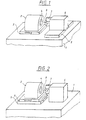
- the processing machine is built on a rigid machine bed 1.
- the spindle 2 is mounted on a slide 3 which is movable in the Z-axis.
- the spindle 2 receives the blank, not shown here, in a workpiece holder 4.
- the Carriage 3 is brought into a suitable position for presetting and then for the duration of processing clamped.
- the tool drive is located on a further carriage 5 which can be moved in the X direction 6, which is realized by a linear motor.
- the rotor 7 of the tool drive 6 carries the turning tool 8.
- Fig. 2 shows a variant of the processing machine, in which not the tool drive 6, but the spindle 2 is mounted on a carriage 5 which can be moved in the X direction is.
- the electrodynamic linear motor provides a possible tool drive accordingly Fig. 3 represents.
- the linear motor consists of a rotor 7, the permanent magnet 9 is equipped and the stator coil system 10. To achieve a low-friction
- the rotor 7 is mounted horizontally and vertically in movement in air bearings 11.
- the runner 7 carries a measuring system 12 for determining the position.
- the dynamic mass balance causes reaction forces caused by the necessary rapid movement of the turning tool 8, balanced and so any Accidental movement of the turning tool avoided, which results in the high surface quality of the processed lens and the accuracy of its optical geometry is made possible.
- FIG. 5 An analog device with hydraulically or pneumatically operating drives shows Fig. 5.
- the runners are realized by pistons 14 running in opposite directions.
- mass balancing can be achieved by applying force to a large mass be effected.
- the machine bed 1 as shown in Fig. 2, as large mass executed.
- the mass is dimensioned so that its resulting movement has an amplitude of less than 0.005 mm.
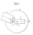
- Fig. 6 shows a machine structure in which instead of a carriage movement in the X direction a pivoting movement of the blank is provided.
- the spindle 2 is closed this purpose stored on a turntable 15.
- the pivot center 16 is located itself on the Z axis.
- the swiveling movement must have a suitable radius r be that can be chosen so that the additional, the pivoting movement superimposed movement of the turning tool 8 in the direction of the Z axis a minimum becomes.
- Fig. 7 Mastery of central singularity is shown in Fig. 7.
- the blank becomes minor in two differing eccentric positions rotated, not to is turned to the spindle axis.
- the illustration shows the off-center positions shown schematically exaggerated.
- the broken line in Fig. 7 is not executed, the area not processed is then covered by the other position.
- the workpiece holder 4 of the spindle 2 can be pivoted slightly for this purpose listed.
- magnetic force caused by switchable electromagnets 17, as shown in FIG. 8, the displacement of the workpiece holder 4 in two different positions up and down by rotating around a pivot point 18 can be achieved.
- Fig. 10 shows a variant of a processing machine in which the dynamic mass balance is exploited to simultaneously the second side of the To edit blanks.
- the spindle 2 is supported on a slide 5.
- the workpiece holder 4 is designed so that the blank from both sides can be edited.
- Tool drives 6, 13 are located on both sides of the spindle 2 provided that work in opposite directions. So the desired optical Effect equally distributed on both sides of the ophthalmic lens.
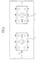
- FIG. 11 shows a block diagram of a control circuit for control and regulation the movements of the spindle 2 and the turning tool 8. It is with a digital controller e.g. worked a signal processor that optimal adjustment allowed to the controlled system. Structure and parameter optimization can function as the workpiece geometry. All quantities describing the system status (mechanical system, tachometers, position measuring systems) are fed to the digital controller. The slow movement in the X direction can also be operated by the controller become. This controlled system is not shown in FIG. 11. Considering of the setpoint, the power amplifiers for the motors are controlled. The required Dynamic range of the amplifier should be 100dB. For modulating fine A corresponding bandwidth must be provided for structures.
- the target data for the movements can be created before processing and stored in a memory. Preferably, however, the target data with the function describing the area Z (r, phi) calculated online.
- Optical surfaces are optically effective Surfaces of lenses, mirrors or other optical components that are through their behavior when transmitting or reflecting electromagnetic radiation distinguish (especially in the infrared, visible and ultraviolet spectral range).
Landscapes
- Engineering & Computer Science (AREA)
- Mechanical Engineering (AREA)
- Grinding And Polishing Of Tertiary Curved Surfaces And Surfaces With Complex Shapes (AREA)
- Eyeglasses (AREA)
- Machine Tool Sensing Apparatuses (AREA)
- Constituent Portions Of Griding Lathes, Driving, Sensing And Control (AREA)
- Moulds For Moulding Plastics Or The Like (AREA)
- Turning (AREA)
- Surface Treatment Of Glass (AREA)
- Treatments Of Macromolecular Shaped Articles (AREA)
- Casting Or Compression Moulding Of Plastics Or The Like (AREA)
Abstract
Description
Die Erfindung betrifft ein Verfahren zum Herstellen von optischen Oberflächen, insbesondere von ophtalmischen Linsen und Formschalen zur Herstellung von ophtalmischen Linsen (insbesondere asphärischen Kunststofflinsen), sowie eine Bearbeitungsmaschine zur Durchführung des Verfahrens.The invention relates to a method for producing optical surfaces, especially of ophthalmic lenses and molded shells for the production of ophthalmic lenses (especially aspherical plastic lenses), as well as a Processing machine for performing the method.
Eine Vorrichtung gemäß Oberbegriff des Anspruchs 1 und ein Verfahren gemäß Oberbegriff des Anspruchs 20 sind aus der EP-A-0 439 425 bekannt.A device according to the preamble of
Optische Oberflächen und insbesondere ophtalmische Linsen mit komplizierter Geometrie, z.B. Gleitsichtgläser, können heute aus Silikatglas oder aus Kunststoff hergestellt werden. Als Silikatlinsen werden sie durch Schleifen und nachfolgendes Polieren hergestellt. Kunststofflinsen werden durch Gießen in einer vorher gefertigten Negativform gefertigt. Die Negativformen, sogenannte Formschalen, werden aus Silikatglas mit der gleichen Methode wie bei der Fertigung von ophtalmischen Linsen, also ebenfalls durch Schleifen und Polieren, hergestellt.Optical surfaces and especially ophthalmic lenses with complicated Geometry, e.g. Progressive lenses can now be made of silicate glass or plastic getting produced. As silicate lenses, they are made by grinding and subsequent Polishing made. Plastic lenses are made by casting in a previously made Negative form made. The negative forms, so-called molded shells, are made Silicate glass with the same method as in the production of ophthalmic lenses, also produced by grinding and polishing.
Nachteilig bei dieser Vorgehensweise ist, daß insbesondere für die Fertigung von ophtalmischen Linsen alle benötigten geometrischen Formen vorrätig gehalten werden müssen.A disadvantage of this procedure is that, in particular for the production of ophthalmic lenses all required geometric shapes are kept in stock have to.
Nachteilig ist außerdem, daß sich bei den mehrstufigen Fertigungsprozessen die Toleranzen der einzelnen Schritte ungünstig auf das Endprodukt auswirken können. Korrekturstrategien sind sehr aufwendig und kompliziert. Mit jedem zusätzlichen Prozeßschritt wird die Situation unübersichtlicher, da Fehler meistens erst am Schluß des Prozesses feststellbar sind und so die Ursache möglicherweise nur schwer zu lokalisieren ist.Another disadvantage is that the tolerances in the multi-stage manufacturing processes of the individual steps can have an adverse effect on the end product. corrective strategies are very complex and complex. With every additional process step the situation becomes more confusing, since errors usually only appear at the end of the Process can be determined and the cause may be difficult to pinpoint is.
Durch die US-PS 5 320 006 ist es bereits bekannt, die Grundform von Kunststofflinsen auf einer geeigneten Drehmaschine zu drehen und sie nachfolgend auf einer Poliermaschine fertig zu bearbeiten, wobei die Krümmung des Polierwerkzeuges gemessen und als Regelgröße für das Drehwerkzeug verwendet wird, um einen möglichst genau an das Polierwerkzeug angepaßten Rohling zu erzeugen und so das Polieren auf ein Minimum zu beschränken. Abgesehen davon, daß immer noch ein aufwendiger Poliervorgang verbleibt, sind mit dieser Methode nur sphärische, allenfalls torisch geformte Brillenlinsen herstellbar. Gleitsichtlinsen weisen komplizierte asphärische Formen auf und können auf diese Weise nicht hergestellt werden.From US Pat. No. 5,320,006 it is already known the basic shape of plastic lenses on a suitable lathe and then on a polishing machine finished machining, the curvature of the polishing tool measured and is used as a control variable for the turning tool to make one as accurate as possible to produce a blank adapted to the polishing tool and thus polishing to limit a minimum. Apart from that, it's still an elaborate With this method, the polishing process remains only spherical, at most toric shaped eyeglass lenses can be produced. Progressive lenses have complicated aspherical lenses Molds and cannot be made in this way.
Der Erfindung liegt die Aufgabe zugrunde, eine vorrichtung und ein Verfahren anzugeben, womit auch geometrisch kompliziert geformte optische Oberflächen und insbesondere ophtalmische Linsen und Formschalen zur Herstellung von ophtalmischen Linsen nach individueller Datenvorgabe in einem einzigen Prozeßschritt direkt gefertigt werden können, wobei keine oder zumindest nur geringe Nacharbeiten zur Fertigstellung der optischen Oberflächen und insbesondere der ophtalmischen Linsen und Formschalen zur Herstellung von ophtalmischen Linsen vonnöten sein sollen.The invention has for its object to provide a device and a method, with what geometrically complex shaped optical surfaces and especially ophthalmic ones Lenses and molded shells for the production of ophthalmic lenses according to individual Data specification can be made directly in a single process step, whereby no or at least only slight reworking to complete the optical surfaces and in particular the ophthalmic lenses and molded shells for manufacturing ophthalmic lenses should be needed.
Erfindungungsgemäß wird die Aufgabe
durch die in Anspruch 1 definierte
Vorrichtung und das in Anspruch 20 angegebene Verfahren
gelöst.According to the invention the task
by that defined in
Durch das erfindungsgemäße Verfahren kann ein Werkzeugstichel so schnell verfahren werden, daß die in Umfangsrichtung auftretenden, durch die asphärische Form bedingten Höhenänderungen aus einem Kunststoffrohling herausgearbeitet werden können. Der Stichel kann einen sehr kleinen Radius haben, wodurch der Eingriff nahezu punktförmig wird. Der Stichel kann aber auch einen Radius von mehreren Millimetern aufweisen. Er kann mit einem monokristallinen Diamanten bestückt sein.A tool stylus can move so quickly by the method according to the invention be that those occurring in the circumferential direction, due to the aspherical shape Changes in height can be worked out from a plastic blank. The stylus can have a very small radius, which makes the intervention almost punctiform becomes. The stylus can also have a radius of several millimeters. It can be set with a monocrystalline diamond.
Die erzeugte Oberfläche ist in der Regel bereits gebrauchsfertig. Gegebenenfalls bedarf es zum Herstellen der Gebrauchsfähigkeit noch einer geringen Nacharbeit durch Polieren. Die Form wird dabei vollständig durch den Drehprozeß bestimmt und durch das Polieren nicht mehr verändert. The surface created is usually ready for use. May be necessary a little reworking to make it usable Polishing. The shape is completely determined by the turning process and by the polishing no longer changed.
Alternativ zum Polieren kann die Oberfläche auch z.B. durch Tauchen in Lack gebrauchsfähig gemacht werden.As an alternative to polishing, the surface can also be e.g. usable by dipping in paint be made.
Neben ophtalmischen Linsen können mit dem Verfahren auch Formschalen zur Herstellung von ophtalmischen Linsen, z.B. aus Metall oder Keramik, hergestellt werden. Polieren ist auch hier nur in sehr geringem Umfang erforderlich. Des weiteren können optische Oberflächen, z.B. andere Linsen oder Spiegel mit komplizierter, nicht-rotationssymmetrischer Form, hergestellt werden.In addition to ophthalmic lenses, the process can also be used to manufacture molded shells ophthalmic lenses, e.g. made of metal or ceramic. Here, too, polishing is only required to a very small extent. Furthermore you can optical surfaces, e.g. other lenses or mirrors with complicated, non-rotationally symmetrical Shape.
Erfindungsgemäß kann in bevorzugter Weise vorgesehen werden, daß die bei der Zustellung entstehende Reaktionskraft durch einen statischen oder dynamischen Massenausgleich ausgeglichen wird.According to the invention it can be provided in a preferred manner that during delivery resulting reaction force through a static or dynamic mass balance is balanced.
Für den Einbau der Linsen oder Spiegel, aber insbesondere der Brillenlinsen in die Brillenfassung, müssen Marken auf der Oberfläche angebracht sein, die eine schnelle Orientierung erlauben. Diese Marken, die bisher zusätzlich mit speziellen Diamant-Werkzeugen oder mit hochenergetischer Laserstrahlung erzeugen werden müssen, können während des Bearbeitungsprozesses nunmehr direkt miterzeugt werden, da es möglich ist, ein punktförmig arbeitendes Werkzeug zu verwenden. Alle Reproduzierbarkeitsprobleme, wie sie bei jedem Maschinenwechsel auftreten, entfallen dadurch. Darüber hinaus können beliebige Zeichen frei programmierbar erzeugt werden. Damit kann jede Linse individuell gekennzeichnet werden.For the installation of the lenses or mirrors, but especially the spectacle lenses in the Eyeglass frame, marks must be affixed to the surface that a quick Allow orientation. These brands, previously with special diamond tools or have to be generated with high-energy laser radiation, can now be generated directly during the machining process, since it it is possible to use a punctiform tool. All reproducibility problems, This means that they no longer occur as they occur with every machine change. In addition, any characters can be freely programmed. In order to each lens can be marked individually.
In analoger Weise betrifft das die Herstellung von Formschalen z.B. zur Herstellung von ophtalmischen Linsen. Auch in den Formschalen können alle Markierungen zur späteren Orientierung der Linse und weitere Zeichen angebracht werden.In an analogous manner, this concerns the production of molded shells e.g. for the production of ophthalmic lenses. All markings can also be used in the molded shells later orientation of the lens and other signs can be attached.
Erfindungsgemäß kann in bevorzugter Weise vorgesehen werden, daß das Drehwerkzeug relativ zur Spindel eine Schwenkbewegung ausführt. Dabei kann der Rohling beim Drehen zusätzlich um einen auf der Z-Achse liegenden Mittelpunkt geschwenkt werden. Alternativ dazu kann das Drehwerkzeug beim Drehen auch zusätzlich um einen auf der Z-Achse liegenden Mittelpunkt geschwenkt werden.According to the invention it can preferably be provided that the turning tool performs a pivoting movement relative to the spindle. The blank can additionally pivoted when rotating around a center point lying on the Z axis become. Alternatively, the turning tool can also be rotated by one center point lying on the Z axis.
Da die Durchbiegung des Linsenmaterials des Materials (Glas oder Kunststoff für Linsen oder Spiegel) keine schnellen Werkzeugbewegungen erfordert, kann man diese Bewegung entweder durch eine langsame Z-Bewegung oder durch eine Schwenkbewegung ersetzen, der der schnelle Z-Antrieb überlagert ist. Die schnelle Z-Bewegung muß dann zur Herstellung von z.B. Gleitsichtlinsen nurmehr einen Hub von ca. 1 mm haben. Diese Vorgehensweise hat insbesondere den Vorteil, daß der zur Formgebung benutzte Bereich des Drehwerkzeuges kleiner wird. Ungleichmäßige Abnutzung des Drehwerkzeuges hat dann kleinere Auswirkungen.Because the deflection of the lens material of the material (glass or plastic for lenses or mirror) does not require fast tool movements, you can do this Movement either by a slow Z movement or by a swivel movement replace, which is superimposed on the fast sterndrive. The fast Z movement must then be used to manufacture e.g. Progressive lenses only have a stroke of approx. 1 mm to have. This procedure has the particular advantage that the shape used area of the turning tool becomes smaller. Uneven wear on the The turning tool then has minor effects.
Ein Problem jedes Drehvorganges ist die Singularität in der Mitte des Werkstückes. Es kann deshalb in bevorzugter Weise vorgesehen sein, daß der Rohling in zwei geringfügig vom Drehzentrum abweichenden off-axis-Positionen gedreht wird.A problem with every turning process is the singularity in the middle of the workpiece. It can therefore be provided in a preferred manner that the blank in two slightly off-axis positions deviating from the turning center.
Dabei bearbeitet man den Rohling so, daß das jeweilige Drehzentrum gerade nur durch den Prozeß in der jeweils anderen Stellung erreicht wird. Man dreht also nicht bis zur Spindelachse.The blank is machined so that the respective turning center is just through the process is reached in the other position. So you don't turn up to Spindle axis.
Bei zu großen radialen Bewegungen kann die Drehbewegung am Rand ins Leere laufen. Man kann dies vermeiden, indem man erfindungsgemäß in X-Richtung die Bahnabstände variiert. Dies erfordert dann auch für diesen Vorschub-Antrieb eine entsprechende Dynamik, die man z.B. durch Anlegen von harmonischen Schwingungen erreichen kann. Auch hierfür ist ein dynamischer Massenausgleich vorteilhaft.If the radial movements are too large, the rotary movement at the edge can be void. This can be avoided by, according to the invention, the path distances in the X direction varied. This then also requires a corresponding one for this feed drive Dynamics, e.g. by applying harmonic vibrations can. Dynamic mass balancing is also advantageous for this.
Der dynamische Massenausgleich erfordert, daß eine zweite Bewegung einer gleich großen Masse mit entgegengesetzter Bewegungsrichtung ausgeführt werden muß. Man kann diese kollineare Bewegung benutzen, um gleichzeitig die Vorder- und die Rückseite z.B. einer Kunststofflinse oder einer zweiten ophtalmischen Linse bzw. eine zweite Formschale zur Herstellung von ophtalmischen Linsen zu bearbeiten. Je nach Flächendesign und verwendetem Rohling kann der durch gleichzeitige Bearbeitung der Vorder- und Rückseite bewirkte Massenausgleich der beiden gegenläufigen schnellen Werkzeuge ausreichen, um die durch die Beschleunigung der Drehwerkzeuge bewirkte Reaktionskraft aufzunehmen. Wird ein solcher Ausgleich nicht vollständig erreicht, ist gegebenenfalls ein dritter kollinearer Massenausgleich erforderlich.Dynamic mass balance requires that a second movement be equal to one large mass must be executed with the opposite direction of movement. you can use this collinear motion to simultaneously move the front and back e.g. a plastic lens or a second ophthalmic lens or one to process the second molded shell for the production of ophthalmic lenses. Depending on The surface design and the blank can be used by simultaneously processing the Front and back brought about mass balancing of the two opposing fast ones Tools are sufficient to achieve the acceleration caused by the turning tools To absorb reaction force. If such compensation is not fully achieved, a third collinear mass balance may be required.
Diese Arbeitsweise hat zur Folge, daß auf der Vorder- und Rückseite des Rohlings im wesentlichen symmetrisch gearbeitet wird. Man verteilt die gewünschte optische Wirkung gleichmäßig auf beide Flächen. Dies kommt dem in der Feinoptik üblichen Gesichtspunkt gleicher optischer Wirkung beider Flächen nahe und eröffnet völlig neue technische Möglichkeiten, da ophtalmische Linsen bisher auf der Rückseite sphärisch oder torisch gestaltet sind.This procedure has the consequence that on the front and back of the blank in is worked essentially symmetrically. The desired optical effect is distributed evenly on both surfaces. This comes from the point of view common in fine optics the same optical effect of both surfaces and opens completely new ones technical possibilities, since ophthalmic lenses were previously spherical on the back or are designed toric.
Zur Positionsbestimmung und Zustandserfassung von Rohling und Drehwerkzeug sind entsprechende Meßsysteme für die lineare und rotatorische Bewegung erforderlich. Erfindungsgemäß ist in bevorzugter Weise vorgesehen, daß die Positionen von Drehwerkzeug und Rohling optoelektronisch abgetastet werden.For determining the position and condition of blank and turning tool appropriate measuring systems for linear and rotary motion are required. According to the invention it is preferably provided that the positions of the turning tool and blank can be scanned optoelectronically.
Die Position der Werkzeugbewegung in Z-Richtung sollte bevorzugt auf mindestens 0,0005mm genau bestimmt werden.The position of the tool movement in the Z direction should preferably be at least 0.0005mm can be determined exactly.
Meßsysteme mit mindestens 0,0005mm Auflösung und der erforderlichen Länge sind z. B. als optoelektronisch abgetastete Maßstäbe oder Laserinterferometer verfügbar. Zur Positionsbestimmung der Drehbewegung eignen sich optoelektronische Drehgeber. Ebenfalls verfügbar sind Tachometer zur Bestimmung der momentanen Bewegungsgeschwindigkeiten.Measuring systems with at least 0.0005mm resolution and the required length are z. B. available as opto-electronically scanned scales or laser interferometer. Optoelectronic rotary encoders are suitable for determining the position of the rotary movement. Tachometers for determining the current movement speeds are also available.
Weiter kann in erfindungsgemäß bevorzugter Weise vorgesehen werden, daß alle den Systemzustand beschreibenden Größen einem digitalen Regelkreis zugeführt werden und die Regelung unter Berücksichtigung der berechneten Geometrie der optischen Oberfläche, insbesondere einer ophtalmischen Linse bzw. einer Formschale zur Herstellung von ophtalmischen Linsen, erfolgt. Den Systemzustand beschreiben insbesondere die Position des Drehwerkzeugs und die der Spindel bzw. des Rohlings, die ständig gemessen und mit den zu erreichenden Daten verglichen werden. Daraus werden dann Korrekturdaten für die Zustellung des Drehwerkzeuges bestimmt.Furthermore, it can be provided in a preferred manner according to the invention that all of the Parameters describing the system state can be fed to a digital control loop and the control taking into account the calculated geometry of the optical Surface, in particular an ophthalmic lens or a molded shell for production of ophthalmic lenses. Describe the system status in particular the position of the turning tool and that of the spindle or blank, the constantly measured and compared with the data to be achieved. From that become correction data for the infeed of the turning tool is then determined.
Alternativ dazu können auch konventionelle analoge Regler eingesetzt werden.Alternatively, conventional analog controllers can also be used.
Weiter kann in erfindungsgemäß bevorzugter Weise vorgesehen werden, daß der linearmotor für die Werkzeugbewegung in Z-Richtung reibungsarm ausgeführt wird.It can further be provided in a preferred manner according to the invention that the linear motor for the Tool movement in the Z direction with little friction is performed.
Weiter kann in erfindungsgemäß bevorzugter Weise vorgesehen werden, daß der Abstand der Spulen und Magnete sowie das Lagerspiel durch thermische Einflüsse nicht verändert werden. Furthermore, it can be provided in a preferred manner according to the invention that the distance the coils and magnets as well as the bearing play due to thermal influences to be changed.
Die inkrementale Verstellung des Drehwerkzeuges wird durch einen Linearmotor bewerkstelligt. Hierzu kann ein elektrodynamischer, hydraulischer oder pneumatischer Linearmotor verwendet werden. Der Linearmotor besteht aus einem Läufer und einem Stator.The incremental adjustment of the turning tool is done by a linear motor accomplished. This can be an electrodynamic, hydraulic or pneumatic Linear motor can be used. The linear motor consists of a rotor and a Stator.
Für den dynamischen Massenausgleich wird in vorteilhafter Weise ein zweiter, gleich aufgebauter Linearmotor eingesetzt, der kollinear mit dem bearbeitenden Motor liegt und mechanisch mit dessen Gehäuse bzw. Stator über eine steife, kraftschlüssige Verbindung gekoppelt ist. Die Motoren werden in entgegengesetzte Richtungen angesteuert. Bei hydraulischen oder pneumatischen Antrieben kann der dynamische Massenausgleich auch über zwei entgegengesetzt laufende Kolben in einem Zylinder hergestellt werden.For dynamic mass balancing, a second, is advantageously the same built linear motor used, which is collinear with the machining motor and mechanically with its housing or stator via a rigid, non-positive connection is coupled. The motors are driven in opposite directions. Dynamic balancing can be used for hydraulic or pneumatic drives also produced by two pistons running in opposite directions in one cylinder become.
Alternativ können die dynamischen Kräfte des schnellen Werkzeugantriebes in eine große Masse eingeleitet werden (statischer Massenausgleich). Dazu wird der schnelle Werkzeugantrieb direkt auf eine große Masse des Maschinenbettes gesetzt. Der X-Schlitten wird unter der Spindel angeordnet. Die große Masse muß so dimensioniert sein, daß die Reaktionsbewegung aus einer Bewegung des schnellen Werkzeugantriebes deutlich kleiner als einige Mikrometer bleibt. Alternatively, the dynamic forces of the fast tool drive can be converted into one large masses are introduced (static mass balancing). This will be the quick one Tool drive placed directly on a large mass of the machine bed. The X-slide is placed under the spindle. The large mass must be dimensioned in this way be that the reaction movement from a movement of the fast tool drive remains significantly smaller than a few micrometers.
Die Lagerung des Motorläufers ist zugleich die Lagerung des Werkzeuges. Als Lager können Luftlager, Luftlager mit unterstützenden Magnetlagern oder hydraulische Lager verwendet werden, die eine reibungsarme Bewegung in Z-Richtung erlauben, Querkräfte aus dem Bearbeitungsprozeß aber aufzunehmen in der Lage sind.The storage of the motor rotor is also the storage of the tool. As a warehouse can be air bearings, air bearings with supporting magnetic bearings or hydraulic bearings used, which allow a low-friction movement in the Z direction, But are able to absorb lateral forces from the machining process.
Die Antriebskräfte werden bevorzugt durch einen Ein- oder Mehrphasen-Linearmotor erzeugt. Einen derartigen Linearmotor kann man mit bewegter Spule oder alternativ mit bewegtem Magneten aufbauen. Die zweite Variante hat den Vorteil, daß die in der Spule anfallende Verlustleistung leichter abgeführt werden kann.The driving forces are preferred by a single or multi-phase linear motor generated. Such a linear motor can be used with a moving coil or alternatively set up with moving magnet. The second variant has the advantage that the in the Coil losses can be dissipated more easily.
Der besondere Vorteil eines derartigen Werkzeugantriebs liegt auch darin, daß durch die Maschinenelemente Lager und Linearmotor der Hub in z-Richtung nicht begrenzt wird. Man kann Hübe in z-Richtung von einigen 10mm realisieren, wobei die Motorcharakteristik über den gesamten Verstellbereich konstant bleibt. Dies ist insbesondere für die Regelung des Motors von Vorteil.The particular advantage of such a tool drive is that the machine elements bearing and linear motor the stroke in the z direction is not limited becomes. Strokes in the z direction of a few 10mm can be achieved, with the motor characteristic remains constant over the entire adjustment range. This is particularly so advantageous for the regulation of the motor.
Die Peltier-Kühlung kann eine Wasserkühlung auf der heißen Seite aufweisen. Mit der Peltier-Kühlung ist die Spulentemperatur auf einen konstanten Temperaturwert , z. B. auf 0,1K genau, regelbar, so daß die Luftspalte auch bei unterschiedlichen Belastungszuständen klein und konstant gehalten werden können.Peltier cooling can have water cooling on the hot side. With Peltier cooling is the coil temperature to a constant temperature value, e.g. B. on 0.1K exactly, adjustable, so that the air gaps even under different load conditions can be kept small and constant.
In der oben bereits angedeuteten Weise kann die Werkzeugbewegung in der X-Achse durch eine Schwenkbewegung ersetzt sein, der der schnelle Z-Antrieb überlagert ist. Die Schwenkachse kann dabei der Spindel oder dem Werkzeugantrieb unterlagert werden.The tool movement in the X-axis can be carried out in the manner already indicated above be replaced by a swivel movement, which is superimposed on the fast sterndrive. The swivel axis can be subordinate to the spindle or the tool drive.
Alternativ können auch bei dieser Anordnung die dynamischen Kräfte des schnellen Werkzeugantriebes in eine große Masse, z.B. in das Maschinenbett, eingeleitet werden. Dazu muß zunächst der Drehtisch in den passenden Radius zum Werkzeug gebracht und anschließend die Spindel auf dem Drehtisch in den gleichen Radius gestellt werden.Alternatively, the dynamic forces of the fast can also with this arrangement Tool drive in a large mass, e.g. into the machine bed. To do this, the rotary table must first be brought to the tool in the appropriate radius and then placed the spindle on the turntable in the same radius become.
Um den Rohling, wie oben ebenfalls angedeutet, in zwei off-axis-Positionen bearbeiten zu können, kann die Spindel in radialer Richtung verschiebbar angeordnet sein. Zum Beispiel könnte der Werkzeughalter nacheinander mit Magnetkraft in zwei umschaltbare Positionen gebracht werden. Anstelle einer linearen Bewegung kann hier auch eine rotatorische Bewegung mit langem Schwenkradius vorgesehen sein. Der zusätzliche Hub in Z-Richtung ist unerheblich, weil die off-axis-Verschiebung nur sehr gering ist.Process around the blank, as also indicated above, in two off-axis positions to be able, the spindle can be arranged displaceably in the radial direction. For example, the tool holder could be switched into two switchable with magnetic force Positions are brought. Instead of a linear movement, here a rotary movement with a long swivel radius can also be provided. The Additional stroke in the Z direction is irrelevant because the off-axis shift is very small is low.
Die Bewegung des zweiten Linearmotors, der den dynamischen Massenausgleich bewirken soll, kann dazu ausgenutzt werden, die Rückseite einer optischen Oberfläche, insbesondere einer ophtalmischen Linse, und/oder gegebenenfalls eine zweite optische Oberfläche, insbesondere eine zweite ophtalmische Linse bzw. eine zweite Formschale zur Herstellung von ophtalmischen Linsen, mit den gleichen optischen Daten zu bearbeiten. Dabei werden die Spindel koaxial zum Rohling und zu beiden Seiten des Rohlings je ein Linearantrieb gelagert. Der zweite Linearantrieb weist ein zusätzliches Drehwerkzeug und ein Meßsystem zur Positionsbestimmung dieses Drehwerkzeuges auf und der Schlitten für die Bewegung des Rohlings in der X-Achse ist unter der Spindel gelagert ist und trägt diese. Die Kopplung der Antriebe erfolgt über eine steife Grundplatte des Maschinenbettes oder besser durch einen Gehäusekäfig, der die Kräfte symmetrisch aufnimmt.The movement of the second linear motor, which causes the dynamic mass balance the back of an optical surface, in particular an ophthalmic lens, and / or optionally a second optical one Surface, in particular a second ophthalmic lens or a second molded shell for the production of ophthalmic lenses with the same optical data. The spindle becomes coaxial with the blank and on both sides of the blank one linear actuator each. The second linear drive has an additional one Turning tool and a measuring system for determining the position of this turning tool on and the carriage for moving the blank in the X-axis is under the Spindle is supported and carries it. The drives are coupled via a rigid one Base plate of the machine bed or better through a housing cage that supports the forces records symmetrically.
Erfindungsgemäß kann zusätzlich vorgesehen sein, daß in diesem Fall ein weiterer dynamischer Massenausgleich dadurch bewirkt ist, daß kollinear zu beiden Linearantrieben ein dritter Linearantrieb angeordnet ist, dessen Gehäuse bzw. Stator mechanisch mit den Gehäusen bzw. Statoren der beiden anderen Linearantriebe über das Maschinenbett gekoppelt ist und der entgegengesetzt zur Kraftrichtung der aus der Bewegung des ersten und zweiten Linearantriebes resultierenden Kraft angesteuert ist.According to the invention it can additionally be provided that in this case another Dynamic mass balance is caused by the fact that it is collinear with both linear drives a third linear drive is arranged, the housing or stator mechanically with the housings or stators of the other two linear drives over the machine bed is coupled and opposite to the direction of force from the movement of the first and second linear drives resulting force is driven.
Neben der Aufnahme der durch die Werkzeugzustellung bewirkten Reaktionskräfte hat diese Variante den weiteren Vorteil, daß auch die Prozeßkräfte am Werkstück weitgehend symmetriert werden.In addition to absorbing the reaction forces caused by the tool delivery this variant has the further advantage that the process forces on the workpiece are largely be symmetrized.
Das Verfahren soll nachstehend anhand von Ausführungsbeispielen näher erläutert
werden. In den zugehörigen Zeichnungen zeigen
Fig. 1 zeigt eine Bearbeitungsmaschine zur Durchführung des erfindungsgemäßen Verfahrens.
Die Bearbeitungsmaschine ist auf einem steifen Maschinenbett 1 aufgebaut.
Die Spindel 2 ist auf einem in der Z-Achse bewegbaren Schlitten 3 gelagert. Die Spindel
2 nimmt den hier nicht gezeigten Rohling in einer Werkstückaufnahme 4 auf. Der
Schlitten 3 wird zur Voreinstellung in eine geeignete Position gebracht und dann für
die Dauer der Bearbeitung festgeklemmt.1 shows a processing machine for carrying out the method according to the invention.
The processing machine is built on a
Auf einem weiteren, in X-Richtung bewegbaren Schlitten 5 befindet sich der Werkzeugantrieb
6, der durch einen Linearmotor realisiert ist. Der Läufer 7 des Werkzeugantriebes
6 trägt das Drehwerkzeug 8. The tool drive is located on a
Fig. 2 zeigt eine Variante der Bearbeitungsmaschine, bei der nicht der Werkzeugantrieb
6, sondern die Spindel 2 auf einem in X-Richtung verfahrbaren Schlitten 5 gelagert
ist.Fig. 2 shows a variant of the processing machine, in which not the
Einen möglichen Werkzeugantrieb stellt der elektrodynamische Linearmotor entsprechend
Fig. 3 dar. Der Linearmotor besteht aus einem Läufer 7, der mit Permanentmagneten
9 ausgerüstet ist und dem Statorspulensystem 10. Zum Erreichen einer reibungsarmen
Bewegung ist der Läufer 7 horizontal und vertikal in Luftlagern 11 gelagert.
Zur Positionsbestimmung trägt der Läufer 7 ein Meßsystem 12.The electrodynamic linear motor provides a possible tool drive accordingly
Fig. 3 represents. The linear motor consists of a
Fig. 4 zeigt ein Beispiel für den dynamischen Massenausgleich des Systems. Dazu ist
ein kollinear zum Werkzeugantrieb 6 liegender Linearantrieb 13 vorgesehen, der allein
dem Ausgleich der bei der schnellen Zustellbewegung entstehenden Reaktionskraft
dient. Die Statoren beider Linearantriebe sind durch das Maschinenbett 1 kraftschlüssig
miteinander gekoppelt. Die Linearantriebe werden beim Bearbeitungsvorgang
gleichzeitig in entgegengesetzte Richtungen angesteuert.4 shows an example of the dynamic mass balance of the system. Is to
a collinear to the
Durch den dynamischen Massenausgleich werden Reaktionskräfte, verursacht durch
die nötige schnelle Bewegung des Drehwerkzeuges 8, ausgeglichen und so jegliche
unbeabsichtigte Bewegung des Drehwerkzeuges vermieden, wodurch die hohe Oberflächengüte
des bearbeiteten Brillenglases und die Genauigkeit seiner optischen Geometrie
ermöglicht wird.The dynamic mass balance causes reaction forces caused by
the necessary rapid movement of the
Eine analoge Einrichtung mit hydraulisch oder mit pneumatisch arbeitenden Antrieben
zeigt Fig. 5. Die Läufer sind dabei durch entgegengesetzt laufende Kolben 14 realisiert.An analog device with hydraulically or pneumatically operating drives
shows Fig. 5. The runners are realized by
Alternativ dazu kann der Massenausgleich durch Krafteinleitung in eine große Masse
bewirkt werden. Dazu wird das Maschinenbett 1, wie es in Fig. 2 gezeigt ist, als
große Masse ausgeführt. Die Masse wird so dimensioniert, daß ihre resultierende Bewegung
eine Amplitude von weniger als 0,005 mm aufweist.Alternatively, mass balancing can be achieved by applying force to a large mass
be effected. For this purpose, the
Fig. 6 zeigt einen Maschinenaufbau, bei dem statt einer Schlittenbewegung in X-Richtung
eine Schwenkbewegung des Rohlings vorgesehen ist. Die Spindel 2 ist zu
diesem Zweck auf einem Drehtisch 15 gelagert. Der Schwenkmittelpunkt 16 befindet
sich auf der Z-Achse. Die Schwenkbewegung muß mit einem passenden Radius r ausgeführt
werden, der so gewählt werden kann, daß die zusätzliche, der Schwenkbewegung
überlagerte Bewegung des Drehwerkzeuges 8 in Richtung der Z-Achse ein Minimum
wird.Fig. 6 shows a machine structure in which instead of a carriage movement in the X direction
a pivoting movement of the blank is provided. The
Die Beherrschung der Mittensingularität zeigt Fig. 7. Der Rohling wird in zwei geringfügig voneinander abweichenden außermittigen Positionen gedreht, wobei nicht bis zur Spindelachse gedreht wird. In der Darstellung sind die außermittigen Positionen schematisch übertrieben gezeigt. Die in Fig. 7 unterbrochene Linie wird nicht ausgeführt, der jeweils nicht bearbeitete Bereich wird dann von der anderen Position überdeckt.Mastery of central singularity is shown in Fig. 7. The blank becomes minor in two differing eccentric positions rotated, not to is turned to the spindle axis. The illustration shows the off-center positions shown schematically exaggerated. The broken line in Fig. 7 is not executed, the area not processed is then covered by the other position.
Die Werkstückaufnahme 4 der Spindel 2 wird zu diesem Zweck geringfügig schwenkbar
aufgeführt. Mittels magnetischer Kraft, bewirkt durch schaltbare Elektromagneten
17, kann, wie in Fig. 8 gezeigt ist, die Verschiebung der Werkstückaufnahme 4 in
zwei verschiedene Positionen nach oben und unten durch Verdrehen um einen Drehpunkt
18 erreicht werden.The
Um in diesem Falle die Drehbewegung am Rand des Rohlings nicht ins Leere laufen
zu lassen, ist gemäß Fig. 9 vorgesehen, die Zustellbewegung in X-Richtung zu variieren.In this case, the rotational movement at the edge of the blank does not come to
Fig. 10 zeigt eine Variante einer Bearbeitungsmaschine, bei der der
dynamische Massenausgleich ausgenutzt wird, um gleichzeitig die zweite Seite des
Rohlings zu bearbeiten. Die Spindel 2 ist in diesem Fall auf einem Schlitten 5 gelagert.
Die Werkstückaufnahme 4 ist so ausgebildet, daß der Rohling von beiden Seiten
bearbeitet werden kann. Auf beiden Seiten der Spindel 2 sind Werkzeugantriebe 6, 13
vorgesehen, die entgegengesetzt gerichtet arbeiten. So kann die gewünschte optische
Wirkung gleichermaßen auf beide Seiten der ophtalmischen Linse verteilt werden.Fig. 10 shows a variant of a processing machine in which the
dynamic mass balance is exploited to simultaneously the second side of the
To edit blanks. In this case, the
Fig. 11 zeigt schließlich ein Blockschaltbild eines Regelkreises zur Steuerung und Regelung
der Bewegungen der Spindel 2 und des Drehwerkzeuges 8. Es wird mit einem
digitalen Regler z.B. einem Signalprozessor gearbeitet, der eine optimale Anpassung
an die Regelstrecke erlaubt. Struktur und Parameteroptimierung können als Funktion
der Werkstückgeometrie erfolgen. Alle den Systemzustand beschreibenden Größen
(mechanisches System, Tachos, Wegmeßsysteme) werden dem digitalen Regler zugeführt.
Die langsame Bewegung in X-Richtung kann ebenfalls von dem Regler bedient
werden. Diese Regelstrecke ist in Fig. 11 nicht ausgeführt. Unter Berücksichtigung
des Sollwertes werden die Leistungsverstärker für die Motoren angesteuert. Die erforderliche
Dynamik der Verstärker sollte bei 100dB liegen. Zur Modulation von feinen
Strukturen ist eine entsprechende Bandbreite vorzusehen. Die Solldaten für die Bewegungen
können vor der Bearbeitung erzeugt und in einem Speicher abgelegt werden.
Vorzugsweise werden die Solldaten aber mit der die Fläche beschreibenden Funktion
Z(r,phi) online berechnet.11 shows a block diagram of a control circuit for control and regulation
the movements of the
Unter einer ophtalmischen Linse in dieser Beschreibung sind Brillenlinsen, Kontaktlinsen und intraokulare Linsen zu verstehen. Optische Oberflächen sind optisch wirksame Oberflächen von Linsen, Spiegeln oder sonstigen optischen Bauteilen, welche sich durch ihr Verhalten bei Transmission oder Reflexion elektromagnetischer Strahlung auszeichnen (insbesondere im infraroten, sichtbaren und ultravioletten Spektralbereich).Under an ophthalmic lens in this description are spectacle lenses, contact lenses and to understand intraocular lenses. Optical surfaces are optically effective Surfaces of lenses, mirrors or other optical components that are through their behavior when transmitting or reflecting electromagnetic radiation distinguish (especially in the infrared, visible and ultraviolet spectral range).
Claims (27)
- Processing machine for producing optical surfaces, in particular ophthalmic lenses and shell moulds for producing ophthalmic lenses, in particular plastic lenses, having, mounted on a stiff machine bed (1), a spindle on which it is possible to hold a blank for optical surface treatment or a blank of a shell mould, and a turning tool (8), which can be moved in the direction of the blank and away from the latter, wherein the turning tool (8) or the spindle (2) can be moved orthogonal to the axial direction of the spindle (X-axis),
characterized in that the drive (6) for the turning tool (8) in the direction of the Z-axis is realized by an incrementally infeeding linear motor,
and in that Peltier cooling is used to cool the coil or coils of the linear motor or linear motors. - Processing machine according to Claim 1, characterized in that water cooling is assigned to the Peltier cooling.
- Processing machine according to Claim 1 or 2,
characterized in that the reaction force effected by the acceleration of the linear drive (6) is dynamically balanced by a second linear drive (13), which is arranged colinearly with the first linear drive (6) and whose housing or stator is mechanically coupled to the housing or stator of the first linear drive (6) via the machine bed (1), and which is driven in the opposite direction to the first linear drive (6). - Processing machine according to Claim 1 or 2,
characterized in that the reaction force effected by the acceleration of the linear drive (6) is dynamically balanced by introducing force into the mass of the machine bed (1). - Processing machine according to Claim 4, characterized in that the carriage (5) for movement along the X-axis is mounted below the spindle (2) and bears the spindle (2).
- Processing machine according to one of Claims 1 to 5, characterized in that the linear drive (6, 13) is a hydraulic motor.
- Processing machine according to one of Claims 1 to 5, characterized in that the linear drive (6, 13) is an electrodynamic linear motor.
- Processing machine according to one of Claims 1 to 7, characterized in that the rotor of the linear motor is on air-cushioned bearings.
- Processing machine according to one of Claims 1 to 7, characterized in that the rotor of the linear motor is mounted by means of air and supporting magnet bearings.
- Processing machine according to one of Claims 1 to 7, characterized in that the rotor of the linear motor is hydraulically mounted.
- Processing machine according to one of Claims 1 to 10, characterized in that optoelectronically scanned scales serve as measuring system for the linear movement of the turning tool (8).
- Processing machine according to one of Claims 1 to 10, characterized in that laser interferometers serve as measuring system for the linear movement of the turning tool (8).
- Processing machine according to one of Claims 1 to 12, characterized in that an optoelectronic rotary transducer serves as measuring system for the rotary movement of the blank.
- Processing machine according to one of Claims 1 to 12, characterized in that a tachometer serves as measuring system for the rotary movement of the blank.
- Processing machine according to one of Claims 1 to 14, characterized in that the movement in the direction of the X-axis is realized by mounting the spindle (2) pivotably about a centre point (16) located on the Z-axis.
- Processing machine according to one of Claims 1 to 14, characterized in that the carriage (5), which can move along the Z-axis and bears the turning tool (8), is mounted pivotably about a centre point located on the Z-axis.
- Processing machine according to one of Claims 1 to 16, characterized in that the spindle (2) is mounted coaxially with the blank, one linear drive (6, 13) each is mounted on the two sides of the blank, the second linear drive (13) has an additional turning tool and a measuring system for determining the position of this turning tool, and the carriage (5) for moving the blank along the X-axis is mounted below the spindle (2) and bears the latter.
- Processing machine according to Claim 17, characterized in that additional dynamic counterbalancing is effected by arranging colinearly with the two linear drives (6, 13) a third linear drive whose housing or stator is mechanically coupled to the housings or stators of the two other linear drives (6, 13) via the machine bed (1), and which is driven in a sense opposite to the direction of the force resulting from the movement of the first and second linear drives.
- Processing machine according to one of Claims 1 to 18, characterized in that at least one digital controller is used to control all the drives and to process the position data of the blank and of the turning tool or tools.
- Method for producing optical surfaces, in particular ophthalmic lenses and shell moulds for producing ophthalmic lenses, in particular aspherical plastic lenses, in which a blank for optical surface treatment or a blank of a shell mould for producing optical surfaces is held on the workpiece support of a spindle axis (Z-axis) of a processing machine and is directly turned to its final shape by means of a turning tool which can execute a relative movement with respect to the blank, it being the case that the turning tool can be moved transverse to the direction of tool movement (X-axis) and that during each spindle revolution the turning tool performs incremental infeeds in the direction of the blank and away from the latter (Z-axis) in accordance with prescribed or online-calculated data of the surface,
characterized in that the processing machine according to one of Claims 1 to 19 is used. - Method according to Claim 20, characterized in that the dynamic counterbalancing is realized entirely or partially by a second turning tool which can be moved in the Z-direction by means of a dedicated drive and acts on the second side of the blank or on a second blank.
- Method according to Claim 20 or 21, characterized in that the finally turned blank is made ready for use by polishing.
- Method according to one of Claims 20 to 22, characterized in that the finally turned blank is made ready for use by being dipped in lacquer.
- Method according to one of Claims 20 to 23, characterized in that the positions of the turning tool and blank are sensed optoelectronically.
- Method according to one of Claims 20 to 24, characterized in that all the parameters describing the system state are fed to a digital control loop, and control is performed taking account of the calculated geometry of the optical surface.
- Method according to one of Claims 20 to 25, characterized in that the position of the turning tool and the spindle and/or the blank are continuously measured and compared with the data to be achieved, and correc) tion data for the infeed of the turning tool are determined therefrom.
- Method according to one of Claims 20 to 26, characterized in that the position of the tool movement in i the Z-direction is determined to an accuracy of at least 0.0005 mm.
Applications Claiming Priority (3)
| Application Number | Priority Date | Filing Date | Title |
|---|---|---|---|
| DE19538274 | 1995-10-14 | ||
| DE19538274 | 1995-10-14 | ||
| PCT/DE1996/001947 WO1997013603A2 (en) | 1995-10-14 | 1996-10-11 | Process for manufacturing optical surfaces and shaping machine for carrying out this process |
Publications (2)
| Publication Number | Publication Date |
|---|---|
| EP0854769A2 EP0854769A2 (en) | 1998-07-29 |
| EP0854769B1 true EP0854769B1 (en) | 2002-02-27 |
Family
ID=7774848
Family Applications (1)
| Application Number | Title | Priority Date | Filing Date |
|---|---|---|---|
| EP96946356A Expired - Lifetime EP0854769B1 (en) | 1995-10-14 | 1996-10-11 | Process for manufacturing optical surfaces and shaping machine for carrying out this process |
Country Status (7)
| Country | Link |
|---|---|
| US (1) | US6523443B1 (en) |
| EP (1) | EP0854769B1 (en) |
| JP (1) | JP3938213B2 (en) |
| AT (1) | ATE213683T1 (en) |
| DE (1) | DE19680863B4 (en) |
| ES (1) | ES2173343T3 (en) |
| WO (1) | WO1997013603A2 (en) |
Cited By (4)
| Publication number | Priority date | Publication date | Assignee | Title |
|---|---|---|---|---|
| DE102004019931A1 (en) * | 2004-04-21 | 2005-11-10 | Schneider Gmbh + Co. Kg | Correction procedure for cutting machines |
| EP1719573A1 (en) * | 2005-05-06 | 2006-11-08 | Satisloh GmbH | Lathe with a one-piece machine support made of concrete polymer |
| CN101687302A (en) * | 2007-07-09 | 2010-03-31 | 卡尔蔡司Smt股份公司 | Method of measuring a deviation of an optical surface from a target shape |
| WO2013117327A3 (en) * | 2012-02-06 | 2013-10-03 | Schneider Gmbh & Co. Kg | Linear drive with a compensation member |
Families Citing this family (35)
| Publication number | Priority date | Publication date | Assignee | Title |
|---|---|---|---|---|
| DE19680863B4 (en) * | 1995-10-14 | 2013-06-13 | Carl Zeiss Vision Gmbh | Method for producing optical surfaces and processing machine for carrying out the method |
| DE19653233A1 (en) * | 1996-12-20 | 1998-07-02 | Schneider Gmbh & Co Kg | High-speed lathe for the production of optically effective surfaces |
| DE19701312A1 (en) * | 1997-01-16 | 1998-07-23 | Zeiss Carl Fa | Spectacle lens with spherical front and multifocal back, and method for its production |
| SE514666C2 (en) * | 1999-07-05 | 2001-04-02 | Sandvik Ab | Method for fixing inserts in PVD coating |
| CA2313830A1 (en) * | 2000-07-13 | 2002-01-13 | Micro Optics Design Corporation | Single point diamond turning lathe with vibration cancelling feature |
| DE10114239A1 (en) * | 2001-03-22 | 2002-10-02 | Loh Optikmaschinen Ag | Device for edge processing of optical lenses |
| DE10143848C2 (en) | 2001-09-06 | 2003-10-02 | Loh Optikmaschinen Ag | Process and device for the surface processing of workpieces made of non-brittle hard materials in optics production and tool therefor |
| US6621241B2 (en) * | 2001-12-20 | 2003-09-16 | Dac International, Inc. | System and method for reducing oscillating tool-induced reaction forces |
| US7765905B2 (en) * | 2002-05-29 | 2010-08-03 | Massachusetts Institute Of Technology | Magnetic micropositioner and method of providing the same |
| US7574947B2 (en) * | 2002-05-29 | 2009-08-18 | Massachusetts Institute Of Technology | Rotary fast tool servo system and methods |
| US7437980B2 (en) * | 2002-05-29 | 2008-10-21 | Massachusetts Institute Of Technology | Flux-biased electromagnetic fast tool servo systems and methods |
| US7275468B2 (en) * | 2002-05-29 | 2007-10-02 | Massachusetts Institute Of Technology | Rotary fast tool servo system and methods |
| DE10250856A1 (en) | 2002-10-25 | 2004-05-13 | Carl Zeiss | Method and device for manufacturing optical glasses |
| WO2005043266A2 (en) * | 2003-10-31 | 2005-05-12 | Massachusetts Institute Of Technology | Variable reluctance fast positioning system and methods |
| DE102004037454A1 (en) * | 2004-08-02 | 2006-02-23 | Carl Zeiss Ag | Method for processing surfaces of workpieces |
| DE102004049951A1 (en) | 2004-10-13 | 2006-04-20 | Schneider Gmbh + Co. Kg | Highly dynamic lens processing machine |
| US7198436B2 (en) * | 2004-10-14 | 2007-04-03 | National Optronics, Inc. | Multi-blade router tool, edger with multi-blade router tool, and method of edging eyeglass lenses |
| DE102005021640B4 (en) * | 2005-05-06 | 2007-08-09 | Satisloh Gmbh | Machine for processing optical workpieces, in particular plastic spectacle lenses |
| WO2007122961A1 (en) * | 2006-04-21 | 2007-11-01 | Hoya Corporation | Lens processing device and method of processing lens |
| DE102006026524A1 (en) * | 2006-06-06 | 2007-12-13 | Satisloh Ag | Machine for processing optical workpieces, in particular plastic spectacle lenses |
| EP1916060B1 (en) * | 2006-10-26 | 2009-05-06 | Satisloh AG | Machine for machining optical work pieces, in particular plastic spectacle lenses |
| DE102007031703A1 (en) * | 2007-07-06 | 2009-01-08 | Satisloh Gmbh | Machine for processing optical workpieces, in particular plastic spectacle lenses |
| TWI533966B (en) * | 2008-09-18 | 2016-05-21 | Flir系統貿易比利時公司 | Systems and methods for machining materials |
| WO2010083244A2 (en) * | 2009-01-13 | 2010-07-22 | Camotion, Inc. | Machine tools with non-rigid robot device using inertial stiffening |
| DE102009011194A1 (en) * | 2009-03-04 | 2010-09-09 | Schneider Gmbh & Co. Kg | Lathe for producing spectacle lenses made of plastic |
| EP2684643A3 (en) * | 2012-05-22 | 2014-04-16 | Schneider GmbH & Co. KG | Device and method for processing an optical workpiece |
| DE102012014399A1 (en) | 2012-07-20 | 2014-05-15 | Carl Zeiss Vision International Gmbh | Device for determining and outputting a spectacle lens type suitable for a spectacle wearer |
| CN102773503B (en) * | 2012-08-21 | 2014-11-05 | 上海现代先进超精密制造中心有限公司 | Single point diamond lathe and method for machining special-shape workpiece |
| CN103878534B (en) * | 2012-12-19 | 2016-05-11 | 鸿准精密模具(昆山)有限公司 | Metalwork processing method |
| CN103878591B (en) * | 2012-12-19 | 2016-12-28 | 鸿准精密模具(昆山)有限公司 | Metalwork processing method |
| DE102013218136B3 (en) | 2013-09-11 | 2015-02-12 | Carl Zeiss Vision International Gmbh | Spectacle lens semi-finished or finished product, process for its production and process for coating a spectacle lens semi-finished or finished product |
| DE102013020597B3 (en) * | 2013-12-13 | 2014-10-30 | FMB Maschinenbaugesellschaft | Balancing device for a bar loading magazine |
| US9618774B2 (en) | 2014-02-10 | 2017-04-11 | Shamir Optical Industry Ltd. | Quasi progressive lenses for eyewear |
| DE102014213393B4 (en) | 2014-07-10 | 2016-12-29 | Carl Zeiss Vision International Gmbh | Set of spectacle lens semi-finished products, computer-implemented method for its design, computer program, computer-readable storage medium, method and apparatus for the production of spectacle lenses and use of a set of spectacle lens semi-finished |
| EP3542956A1 (en) | 2018-03-23 | 2019-09-25 | Carl Zeiss Vision International GmbH | Method for manufacturing spectacle lenses according to a prescription |
Family Cites Families (20)
| Publication number | Priority date | Publication date | Assignee | Title |
|---|---|---|---|---|
| US543504A (en) * | 1895-07-30 | Machine for cutting dough | ||
| CH566186A5 (en) * | 1973-09-13 | 1975-09-15 | Fontainemelon Fabrique D Horlo | |
| US4254065A (en) * | 1979-04-04 | 1981-03-03 | Ratkowski Donald J | Injection molding of contact lenses |
| US4455901A (en) * | 1981-10-09 | 1984-06-26 | Bausch & Lomb Incorporated | Apparatus for controlling lathed contact lens thickness |
| JPS59110362A (en) * | 1982-12-15 | 1984-06-26 | Amada Co Ltd | Linear motor |
| US4711035A (en) * | 1986-08-04 | 1987-12-08 | Gerber Scientific Products, Inc. | Method and apparatus for making a pattern for a lens opening in an eyeglass frame |
| US4839545A (en) * | 1987-10-16 | 1989-06-13 | Anwar Chitayat | Cooling system for linear motor |
| DE3911986A1 (en) * | 1989-04-12 | 1990-10-18 | Benzinger Carl Gmbh & Co | METHOD AND DEVICE FOR MOLDING WORKPIECES |
| FR2653949B1 (en) * | 1989-10-30 | 1992-02-07 | Celduc Const Elect Centre | COOLING DEVICE FOR LINEAR MOTOR INDUCTOR. |
| ES2041201T3 (en) * | 1990-01-24 | 1993-11-01 | Ciba-Geigy Ag | DEVICE FOR THE MANUFACTURE OF A CONTACT LENS WITH A FRONT SURFACE AND / OR A REAR SURFACE, ESPECIALLY SPHERICAL. |
| US5217335A (en) * | 1990-04-24 | 1993-06-08 | National Optronics, Inc. | Plastic lens generator and method |
| JP3026824B2 (en) * | 1990-07-31 | 2000-03-27 | 株式会社メニコン | Aspherical lens manufacturing equipment |
| DE4125707C2 (en) * | 1991-08-02 | 1994-08-04 | Hecht Gmbh Kontaktlinsen | Device for producing a bifocal contact lens and contact lens produced therewith |
| US5485771A (en) * | 1991-09-27 | 1996-01-23 | Coburn Optical Industries, Inc. | Apparatus for generating ophthalmic products from blanks and a method of operating same |
| US5320006A (en) * | 1991-09-27 | 1994-06-14 | Coburn Optical Industries, Inc. | Methods and apparatus for producing ophthalmic lenses |
| JP2995128B2 (en) * | 1993-02-08 | 1999-12-27 | 株式会社メニコン | Holding device for toric lens cutting |
| ES2109464T3 (en) * | 1993-09-06 | 1998-01-16 | Voumard Machines Co Sa | PROCEDURE AND MACHINING DEVICE, IN PARTICULAR GRINDER WITH BALANCED SWING MOVEMENT. |
| US5794498A (en) * | 1994-10-19 | 1998-08-18 | Taylor Hobson Limited | In-situ method and apparatus for blocking lenses |
| US5724120A (en) * | 1995-10-02 | 1998-03-03 | Svochak; Jan B. | Multifocal contact lens and method and apparatus for making the same |
| DE19680863B4 (en) * | 1995-10-14 | 2013-06-13 | Carl Zeiss Vision Gmbh | Method for producing optical surfaces and processing machine for carrying out the method |
-
1996
- 1996-10-11 DE DE19680863T patent/DE19680863B4/en not_active Expired - Lifetime
- 1996-10-11 US US09/051,629 patent/US6523443B1/en not_active Expired - Lifetime
- 1996-10-11 JP JP51463397A patent/JP3938213B2/en not_active Expired - Lifetime
- 1996-10-11 AT AT96946356T patent/ATE213683T1/en not_active IP Right Cessation
- 1996-10-11 WO PCT/DE1996/001947 patent/WO1997013603A2/en active IP Right Grant
- 1996-10-11 ES ES96946356T patent/ES2173343T3/en not_active Expired - Lifetime
- 1996-10-11 EP EP96946356A patent/EP0854769B1/en not_active Expired - Lifetime
Cited By (8)
| Publication number | Priority date | Publication date | Assignee | Title |
|---|---|---|---|---|
| DE102004019931A1 (en) * | 2004-04-21 | 2005-11-10 | Schneider Gmbh + Co. Kg | Correction procedure for cutting machines |
| DE102004019931B4 (en) * | 2004-04-21 | 2012-01-05 | Schneider Gmbh & Co. Kg | Correction procedure for cutting machines |
| EP1719573A1 (en) * | 2005-05-06 | 2006-11-08 | Satisloh GmbH | Lathe with a one-piece machine support made of concrete polymer |
| DE102005021638A1 (en) * | 2005-05-06 | 2006-11-16 | Satisloh Gmbh | Lathe for processing optical workpieces |
| DE102005021638B4 (en) * | 2005-05-06 | 2007-03-29 | Satisloh Gmbh | Lathe for processing optical workpieces |
| CN101687302A (en) * | 2007-07-09 | 2010-03-31 | 卡尔蔡司Smt股份公司 | Method of measuring a deviation of an optical surface from a target shape |
| CN101687302B (en) * | 2007-07-09 | 2013-06-05 | 卡尔蔡司Smt有限责任公司 | Aspherical, and amplitude configuration and projection lens |
| WO2013117327A3 (en) * | 2012-02-06 | 2013-10-03 | Schneider Gmbh & Co. Kg | Linear drive with a compensation member |
Also Published As
| Publication number | Publication date |
|---|---|
| DE19680863B4 (en) | 2013-06-13 |
| JP2007050509A (en) | 2007-03-01 |
| US6523443B1 (en) | 2003-02-25 |
| ATE213683T1 (en) | 2002-03-15 |
| JP3938213B2 (en) | 2007-06-27 |
| WO1997013603A2 (en) | 1997-04-17 |
| DE19680863D2 (en) | 1999-03-11 |
| JP4572187B2 (en) | 2010-10-27 |
| WO1997013603A3 (en) | 1997-06-12 |
| ES2173343T3 (en) | 2002-10-16 |
| EP0854769A2 (en) | 1998-07-29 |
| JP2000515074A (en) | 2000-11-14 |
Similar Documents
| Publication | Publication Date | Title |
|---|---|---|
| EP0854769B1 (en) | Process for manufacturing optical surfaces and shaping machine for carrying out this process | |
| WO1997013603A9 (en) | Process for manufacturing optical surfaces and shaping machine for carrying out this process | |
| EP0849038B1 (en) | High speed lathe for manufacturing optical active surfaces | |
| DE10029967B4 (en) | Device for processing optical workpieces | |
| EP1764185B1 (en) | An apparatus and method for the production of micro structures | |
| EP3463746B1 (en) | Machine for processing optically effective surfaces | |
| US3881378A (en) | Machine for producing aspherical surfaces | |
| EP4190488A1 (en) | Machining unit, in particular for a centering machine for workpieces such as optical lenses | |
| EP0685298B2 (en) | Procedure of and device for fabricating aspheric lens surfaces | |
| EP2684643A2 (en) | Device and method for processing an optical workpiece | |
| DE602004000175T2 (en) | High speed cutting process for producing a curved workpiece surface | |
| DE19751750B4 (en) | Method and device for producing polishable optical lenses from lens blanks | |
| DE19846260A1 (en) | Device for grinding and polishing optical lenses connects to a cast metal machine frame with feeder channels for heating and cooling agents while operating slides for grinding tools | |
| EP0159383A1 (en) | Machine for grinding toric surfaces of optical lenses | |
| DE102004020990B4 (en) | Apparatus and method for producing microstructures | |
| EP0440578A1 (en) | Device for machining curved planes onto moulds for optical or ophthalmic lenses | |
| DE102007050470A1 (en) | Lens-polishing method for producing optically active surfaces by polishing rough-ground lenses uses large-surface polishing tools and 5-axle computerized numerically controlled polishing machines with work-piece/tool spindles | |
| EP0999004A2 (en) | Chuck for a machine tool | |
| JP2002542048A (en) | Method and apparatus for creating the ultimate surface on an ophthalmic lens | |
| US3704554A (en) | Lens processing machine with movable workpiece spindle | |
| EP0384907B1 (en) | Method and device for producing an article from a blank | |
| DE2659489A1 (en) | Milling machine for aspherical faces of optical lenses - has workpiece carrier on cross table with X and Y slides movable independently | |
| CA2220371C (en) | Apparatus and method for generating ultimate surfaces on ophthalmic lenses | |
| DE102021133373A1 (en) | MACHINING OF EXTRA-AXIAL OPTICAL WORKPIECES | |
| CH674325A5 (en) | Machine for producing workpieces with concave or convex surfaces - has table which can be swung about vertical axis and carrying slide which carries workpiece |
Legal Events
| Date | Code | Title | Description |
|---|---|---|---|
| PUAI | Public reference made under article 153(3) epc to a published international application that has entered the european phase |
Free format text: ORIGINAL CODE: 0009012 |
|
| 17P | Request for examination filed |
Effective date: 19980512 |
|
| AK | Designated contracting states |
Kind code of ref document: A2 Designated state(s): AT CH ES FR GB LI NL |
|
| 17Q | First examination report despatched |
Effective date: 19991130 |
|
| GRAG | Despatch of communication of intention to grant |
Free format text: ORIGINAL CODE: EPIDOS AGRA |
|
| GRAG | Despatch of communication of intention to grant |
Free format text: ORIGINAL CODE: EPIDOS AGRA |
|
| GRAH | Despatch of communication of intention to grant a patent |
Free format text: ORIGINAL CODE: EPIDOS IGRA |
|
| GRAH | Despatch of communication of intention to grant a patent |
Free format text: ORIGINAL CODE: EPIDOS IGRA |
|
| REG | Reference to a national code |
Ref country code: GB Ref legal event code: IF02 |
|
| RAP1 | Party data changed (applicant data changed or rights of an application transferred) |
Owner name: CARL ZEISS |
|
| GRAA | (expected) grant |
Free format text: ORIGINAL CODE: 0009210 |
|
| AK | Designated contracting states |
Kind code of ref document: B1 Designated state(s): AT CH ES FR GB LI NL |
|
| REF | Corresponds to: |
Ref document number: 213683 Country of ref document: AT Date of ref document: 20020315 Kind code of ref document: T |
|
| REG | Reference to a national code |
Ref country code: CH Ref legal event code: EP |
|
| GBT | Gb: translation of ep patent filed (gb section 77(6)(a)/1977) |
Effective date: 20020503 |
|
| REG | Reference to a national code |
Ref country code: CH Ref legal event code: NV Representative=s name: E. BLUM & CO. PATENTANWAELTE |
|
| ET | Fr: translation filed | ||
| REG | Reference to a national code |
Ref country code: ES Ref legal event code: FG2A Ref document number: 2173343 Country of ref document: ES Kind code of ref document: T3 |
|
| PLBE | No opposition filed within time limit |
Free format text: ORIGINAL CODE: 0009261 |
|
| STAA | Information on the status of an ep patent application or granted ep patent |
Free format text: STATUS: NO OPPOSITION FILED WITHIN TIME LIMIT |
|
| 26N | No opposition filed |
Effective date: 20021128 |
|
| PGFP | Annual fee paid to national office [announced via postgrant information from national office to epo] |
Ref country code: AT Payment date: 20061011 Year of fee payment: 11 |
|
| PGFP | Annual fee paid to national office [announced via postgrant information from national office to epo] |
Ref country code: NL Payment date: 20061016 Year of fee payment: 11 |
|
| REG | Reference to a national code |
Ref country code: CH Ref legal event code: PFA Owner name: CARL ZEISS Free format text: CARL ZEISS# #73446 OBERKOCHEN (DE) -TRANSFER TO- CARL ZEISS# #73446 OBERKOCHEN (DE) |
|
| NLV4 | Nl: lapsed or anulled due to non-payment of the annual fee |
Effective date: 20080501 |
|
| PG25 | Lapsed in a contracting state [announced via postgrant information from national office to epo] |
Ref country code: AT Free format text: LAPSE BECAUSE OF NON-PAYMENT OF DUE FEES Effective date: 20071011 |
|
| PG25 | Lapsed in a contracting state [announced via postgrant information from national office to epo] |
Ref country code: NL Free format text: LAPSE BECAUSE OF NON-PAYMENT OF DUE FEES Effective date: 20080501 |
|
| REG | Reference to a national code |
Ref country code: FR Ref legal event code: PLFP Year of fee payment: 20 |
|
| PGFP | Annual fee paid to national office [announced via postgrant information from national office to epo] |
Ref country code: CH Payment date: 20151021 Year of fee payment: 20 Ref country code: GB Payment date: 20151021 Year of fee payment: 20 |
|
| PGFP | Annual fee paid to national office [announced via postgrant information from national office to epo] |
Ref country code: ES Payment date: 20151028 Year of fee payment: 20 Ref country code: FR Payment date: 20151023 Year of fee payment: 20 |
|
| REG | Reference to a national code |
Ref country code: CH Ref legal event code: PL |
|
| REG | Reference to a national code |
Ref country code: GB Ref legal event code: PE20 Expiry date: 20161010 |
|
| REG | Reference to a national code |
Ref country code: ES Ref legal event code: FD2A Effective date: 20170126 |
|
| PG25 | Lapsed in a contracting state [announced via postgrant information from national office to epo] |
Ref country code: GB Free format text: LAPSE BECAUSE OF EXPIRATION OF PROTECTION Effective date: 20161010 |
|
| PG25 | Lapsed in a contracting state [announced via postgrant information from national office to epo] |
Ref country code: ES Free format text: LAPSE BECAUSE OF EXPIRATION OF PROTECTION Effective date: 20161012 |