EP0527397B1 - Vorrichtung zum Herstellen einer Bifokal-Contactlinse - Google Patents
Vorrichtung zum Herstellen einer Bifokal-Contactlinse Download PDFInfo
- Publication number
- EP0527397B1 EP0527397B1 EP92113036A EP92113036A EP0527397B1 EP 0527397 B1 EP0527397 B1 EP 0527397B1 EP 92113036 A EP92113036 A EP 92113036A EP 92113036 A EP92113036 A EP 92113036A EP 0527397 B1 EP0527397 B1 EP 0527397B1
- Authority
- EP
- European Patent Office
- Prior art keywords
- radius
- lens
- symmetry
- distance vision
- vision section
- Prior art date
- Legal status (The legal status is an assumption and is not a legal conclusion. Google has not performed a legal analysis and makes no representation as to the accuracy of the status listed.)
- Expired - Lifetime
Links
Images


Classifications
-
- G—PHYSICS
- G02—OPTICS
- G02C—SPECTACLES; SUNGLASSES OR GOGGLES INSOFAR AS THEY HAVE THE SAME FEATURES AS SPECTACLES; CONTACT LENSES
- G02C7/00—Optical parts
- G02C7/02—Lenses; Lens systems ; Methods of designing lenses
- G02C7/04—Contact lenses for the eyes
- G02C7/041—Contact lenses for the eyes bifocal; multifocal
-
- B—PERFORMING OPERATIONS; TRANSPORTING
- B24—GRINDING; POLISHING
- B24B—MACHINES, DEVICES, OR PROCESSES FOR GRINDING OR POLISHING; DRESSING OR CONDITIONING OF ABRADING SURFACES; FEEDING OF GRINDING, POLISHING, OR LAPPING AGENTS
- B24B13/00—Machines or devices designed for grinding or polishing optical surfaces on lenses or surfaces of similar shape on other work; Accessories therefor
- B24B13/0012—Machines or devices designed for grinding or polishing optical surfaces on lenses or surfaces of similar shape on other work; Accessories therefor for multifocal lenses
-
- B—PERFORMING OPERATIONS; TRANSPORTING
- B24—GRINDING; POLISHING
- B24B—MACHINES, DEVICES, OR PROCESSES FOR GRINDING OR POLISHING; DRESSING OR CONDITIONING OF ABRADING SURFACES; FEEDING OF GRINDING, POLISHING, OR LAPPING AGENTS
- B24B13/00—Machines or devices designed for grinding or polishing optical surfaces on lenses or surfaces of similar shape on other work; Accessories therefor
- B24B13/06—Machines or devices designed for grinding or polishing optical surfaces on lenses or surfaces of similar shape on other work; Accessories therefor grinding of lenses, the tool or work being controlled by information-carrying means, e.g. patterns, punched tapes, magnetic tapes
-
- G—PHYSICS
- G02—OPTICS
- G02C—SPECTACLES; SUNGLASSES OR GOGGLES INSOFAR AS THEY HAVE THE SAME FEATURES AS SPECTACLES; CONTACT LENSES
- G02C7/00—Optical parts
- G02C7/02—Lenses; Lens systems ; Methods of designing lenses
- G02C7/04—Contact lenses for the eyes
- G02C7/041—Contact lenses for the eyes bifocal; multifocal
- G02C7/045—Sectorial configuration
-
- G—PHYSICS
- G05—CONTROLLING; REGULATING
- G05B—CONTROL OR REGULATING SYSTEMS IN GENERAL; FUNCTIONAL ELEMENTS OF SUCH SYSTEMS; MONITORING OR TESTING ARRANGEMENTS FOR SUCH SYSTEMS OR ELEMENTS
- G05B19/00—Program-control systems
- G05B19/02—Program-control systems electric
- G05B19/18—Numerical control [NC], i.e. automatically operating machines, in particular machine tools, e.g. in a manufacturing environment, so as to execute positioning, movement or co-ordinated operations by means of program data in numerical form
- G05B19/182—Numerical control [NC], i.e. automatically operating machines, in particular machine tools, e.g. in a manufacturing environment, so as to execute positioning, movement or co-ordinated operations by means of program data in numerical form characterised by the machine tool function, e.g. thread cutting, cam making, tool direction control
- G05B19/184—Generation of cam-like surfaces
Definitions
- the invention relates to a bifocal contact lens according to the preamble of claim 4 and a device according to the preamble of claim 1 for producing such a contact lens.
- a contact lens according to the preamble of claim 4 is known from EP-A-0 248 489.
- the near part is tilted relative to the far part so that the edge of the near part merges smoothly into the surface of the far part.
- the object of the invention is to provide a bifocal contact lens which has a kink-free transition from the far part to the near part, the optical quality in the center of the lens being unaffected. Furthermore, a device should be created with which such a contact lens can be produced.
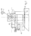
- a support 2 is mounted on a frame 1 and can be moved on a cross slide both along the symmetry axis 22 shown and in a direction transverse thereto.
- the support 2 carries an eccentric head 3 with a lens holder 4 connected to it.
- the lens holder 4 is, as can best be seen from FIG. 2, in the form of a rod which extends parallel to the axis of symmetry of the eccentric head and on a line passing through the axis of symmetry Straight line is displaceable relative to the axis of symmetry.
- the lens holder has a bore 5 into which a mushroom-shaped holder 7, on which the lens blank 8 is clamped, is inserted and held in place by means of a locking screw 6.
- a drive 23 is provided for adjusting the eccentricity of the position of the lens holder 4.
- a carriage 9 with a holder for a diamond stylus 10 is provided.
- the carriage 9 is connected via a bearing to the frame 1 in such a way that the holder for the diamond stylus 10 is on the one hand pivotably arranged on a radius 11, the center of which coincides with the axis of symmetry of the eccentric head 3 when the support 2 is seen in its transverse position in its zero position stands.
- the holder for the diamond stylus 10 itself is displaceable so that its distance from the axis of symmetry 22 of the eccentric head is adjustable.
- the diamond stylus 10 lies with its cutting tip at the level of the axis of symmetry 22.
- a drive 12 is provided for moving the carriage 9 back and forth perpendicular to the axis of symmetry 22 of the eccentric head 3.
- a start switch 13 for switching on the drive 12 and a limit switch 14 for switching off the drive 12 and the drive 23 are provided.
- the device for pivoting the carriage 9 has a release pin 15 which can be adjusted circumferentially to the degree and which, in cooperation with the start switch 13 or limit switch 14, switches the drive 12 on or off. By setting the trigger pin 15, the starting position and thus the zone height of the contact lens can be set.
- a controller 16 is provided which is acted upon on the input side by the output signal from the start switch 13 and limit switch 14 and the extensive setting of the trigger pin 15. On the output side, the control is connected to the drive 12 in the slide 9 and to the drive 23 for adjusting the eccentricity.
- the holder 7 with the clamped lens blank 8 is inserted into the bore 5 of the lens holder 4 in the manner described above, and fixedly mounted by means of the locking screw 6.
- a radius R 1 of, for example, 8 mm is first set in that the diamond stylus 10 corresponds to the radius R 1 the distance from the axis of symmetry of the eccentric head is set.
- the diamond 10 is then moved with the radius R 1 from the upper edge 17 of the lens blank 8 while simultaneously rotating the lens blank by switching on the support 2 and thus cuts the distant part 19 of the lens to be shaped.
- the middle edge 18 passes through the intersection of the axis of symmetry of the eccentric head and the radius of the diamond stylus 10.
- the near part 20 should have a smaller radius R 2 of, for example, 7.5 mm.
- the lens holder 4 on the eccentric head 3 is displaced at the location of the middle edge 18 such that the distance of the lens surfaces from the axis of symmetry 22 is reduced from 8 to 7.5 mm.
- the slide 9 and thus the diamond stylus 10 are displaced towards the center point in such a way that the radius is reduced from previously 8 mm to 7.5 mm.
- the near part 20 is then cut by moving the diamond stylus 10 on the radius 11. This process creates the lens shown in perspective in FIG. 1 with a dividing line between the distant part and the near part along the middle edge 18. In the middle of the lens, the transition is stepless, but the step becomes increasingly larger towards the edge. In the example, the step height is 0.137 mm high with a lens diameter of 9.6 mm.
- the controller 16 drives the drive 12 for the slide and thus the diamond stylus 10 in such a way that while simultaneously pivoting the stylus on the circular slide from the location of the central edge over the preset range of approximately 10 towards the upper edge 17 of the distant part, the radius changes continuously so that at the end of the angular range it is equal to the radius R 2 plus the value of the step height, that is (0.75 + 0.137) mm.
- the lens holder 4 is displaced on the eccentric head 3 such that the distance of the lens surface from the axis of symmetry 23 of R 2 (thus 7.5 mm in the example) is also increased by the zone height at the same time. It is thereby achieved that a section 21 is removed, which extends laterally from the central edge 18 to the preset angular range and in which the surface of the near part 20 merges continuously into the surface of the distant part 19. In the central area of the lens there is no impairment of the optical quality. The edge regions 21 are of no importance for the optical quality of the lens.
- the continuous transition eliminates the cosmetic disadvantages and disadvantages encountered in the prior art during the day.
- the finished lens with the sliding transition is shown in Fig. 1 b.
Landscapes
- Physics & Mathematics (AREA)
- Engineering & Computer Science (AREA)
- Ophthalmology & Optometry (AREA)
- Health & Medical Sciences (AREA)
- General Physics & Mathematics (AREA)
- General Health & Medical Sciences (AREA)
- Optics & Photonics (AREA)
- Mechanical Engineering (AREA)
- Human Computer Interaction (AREA)
- Manufacturing & Machinery (AREA)
- Automation & Control Theory (AREA)
- Grinding And Polishing Of Tertiary Curved Surfaces And Surfaces With Complex Shapes (AREA)
- Eyeglasses (AREA)
Description
- Die Erfindung betrifft eine bifokale Contactlinse nach dem Oberbegriff des Anspruches 4 sowie eine Vorrichtung gemäß Oberbegriff des Anspruchs 1 zum Herstellen einer derartigen Contactlinse.
- Bei dem Herstellen einer bifokalen Contactlinse mit einer bekannten Vorrichtung fallen zwar die Flächen von Nahteil und Fernteil der Linse im Mittelpunkt zusammen. Angrenzend an den Mittelpunkt jedoch entsteht zur Seite hin eine stufenförmige Trennlinie, die sowohl aus Gründen der besseren Verträglichkeit als auch aus ästhetischen Gründen unerwünscht ist.
- Aus der EP-A-0 248 489 ist eine Contactlinse nach dem Oberbegriff des Anspruches 4 bekannt. Hierbei ist das Nahteil relativ zum Fernteil so gekippt, daß der Rand des Nahteiles stufenlos in die Fläche des Fernteiles übergeht.
- Aus der CH-A-674 325 ist eine Vorrichtung zum Herstellen asphärischer Torusflächen und damit auch zum Herstellen einer Bifokal-Contactlinse bekannt. Mit dieser dem Oberbegriff des Anspruchs 1 entsprechenden Vorrichtung können sowohl konkave als auch konvexe asphärische Flächen hergestellt werden.
- Aufgabe der Erfindung ist es, eine Bifokal-Contactlinse zu schaffen, die einen knickfreien Übergang von Fernteil zum Nahteil aufweist, wobei die optische Qualität in Zentrum der Linse unbeeinträchtigt ist. Ferner solle eine Vorrichtung geschaffen werden, mit der eine derartige Contactlinse herstellbar ist.
- Diese Aufgabe wird durch die im Patenanspruch 1 gekennzeichnete Vorrichtung gelöst. Eine damit hergestellte Bifokal-Contactlinse ist im Patentanspruch 4 gekennzeichnet.
- Weitere Merkmale und Zweckmäßigkeiten der Erfindung ergeben sich aus der Beschreibung eines Ausführungsbeispieles anhand der Figuren. Von den Figuren zeigen:
- Fig. 1 eine Draufsicht auf eine schematisch dargestellte Vorrichtung zum Herstellen der Bifokal-Contactlinse;
- Fig 1 a eine perspektivische Darstellung einer Linse mit Trennstufe;
- Fig. 1 b eine perspektivische Darstellung einer Linse ohne Trennstufe;
- Fig. 2 eine Stirnansicht mit der in Fig. 1. gezeigten Vorrichtung;
- Fig. 3 eine Draufsicht auf die erfindungsgemäß hergestellte Contactlinse;
- Fig. 4 die Linse entlang der Schnittlinie IV/IV in Fig. 3;
- Fig. 5 eine Schnittdarstellung entlang der Schnittlinie V/V in Fig. 3.
- Auf einem Rahmen 1 ist ein Support 2 montiert, der auf einem Kreuzschlitten sowohl entlang der gezeigten Symmetrieachse 22, als auch in einer Richtung quer dazu bewegbar ist. Der Support 2 trägt einen Excenterkopf 3 mit einem mit diesem verbundenen Linsenhalter 4. Der Linsenhalter 4 ist, wie am besten aus Fig. 2 ersichtlich ist, als eine Stange ausgebildet, die sich parallel zur Symmetrieachse des Excenterkopfes erstreckt und auf einer durch die Symmetrieachse gehenden Geraden relativ zur Symmetrieachse verschiebbar ist. Der Linsenhalter weist eine Bohrung 5 auf, in die ein pilzförmiger Halter 7, auf dem der Linsenrohling 8 aufgespannt ist, eingesetzt und mittels einer Arretierschraube 6 festgehalten wird. Es ist ein Antrieb 23 zum Verstellen der Exzentizität der Lage des Linsenhaltes 4 vorgesehen.
- Ferner ist ein Schlitten 9 mit einem Halter für einen Diamantstichel 10 vorgesehen. Der Schlitten 9 ist über eine Lagerung mit dem Rahmen 1 derart verbunden, daß der Halter für den Diamantstichel 10 einerseits auf einem Radius 11 schwenkbar angeordnet ist, dessen Mittelpunkt mit der Symmetrieachse des Excenterkopfes 3 zusammenfällt, wenn der Support 2 in Querrichtung gesehen in seiner Nullstellung steht. Der Halter für den Diamantstichel 10 selbst ist so verschiebbar, daß sein Abstand zur Symmetrieachse 22 des Excenterkopfes einstellbar ist. Der Diamantstichel 10 liegt mit seiner Schneidspitze auf der Höhe der Symmetrieachse 22. Es ist ein Antrieb 12 zum Hin- und Herbewegen des Schlittens 9 senkrecht zur Symmetrieachse 22 des Excenterkopfes 3 vorgesehen. Wie am besten aus Fig. 1 ersichtlich ist, sind ein Startschalter 13 zum Einschalten des Antriebes 12 und ein Endschalter 14 zum Ausschalten des Antriebes 12 und des Antriebes 23 vorgesehen. Die Einrichtung zum Schwenken des Schlittens 9 weist einen nach Graden umfangsmäßig einstellbaren Auslösestift 15 auf, der im Zusammenwirken mit dem Startschalter 13 bzw. Endschalter 14 den Antrieb 12 ein- bzw. ausschaltet. Durch Einstellen des Auslösestiftes 15 kann die Startposition und somit die Zonenhöhe der Contactlinse eingestellt werden.
- Es ist eine Steuerung 16 vorgesehen, die eingangsseitig mit dem Ausgangssignal von Startschalter 13 und Endschalter 14 und der umfangmä- ßigen Einstellung des Auslösestiftes 15 beaufschlagt wird. Ausgangsseitig ist die Steuerung mit dem Antrieb 12 in des Schlittens 9 und mit dem Antrieb 23 für die Verstellung der Exzentrizität verbunden.
- Im Betrieb wird der Halter 7 mit dem aufgespannten Linsenrohling 8 in der oben beschriebenen Weise in die Bohrung 5 des Linsenhalters 4 eingesetzt, und mittels der Arretierschraube 6 fest montiert.
- Es wird zunächst ein Radius R1 von beispielsweise 8 mm dadurch eingestellt, daß der Diamantstichel 10 auf einen dem Radius R1 entsprechendenAbstand von der Symmetrieachse des Excenterkopfes eingestellt wird. Der Diamant 10 wird dann mit dem Radius R1 vom oberen Rand 17 des Linsenrohlings 8 bei gleichzeitigen Rotieren des Linsenrohlings durch Einschalten des Supports 2 bewegt und schneidet damit den Fernteil 19 der zu formenden Linse. Der mittlere Rand 18 geht durch den Schnittpunkt von der Symmetrieachse des Excenterkopfes und dem Radius des Diamantstichels 10.
- Der Nahteil 20 soll einen kleineren Radius R2 von beispielsweise 7,5 mm haben. Zu diesem Zweck wird an der Stelle des mittleren Randes 18 der Linsenhalter 4 am Excenterkopf 3 so versetzt, daß der Abstand der Linsenflächen von der Symmetrieachse 22 von vorher 8 auf jetzt 7,5 mm verkleinert wird. Gleichzeitig wird der Schlitten 9 und damit der Diamantstichel 10 so zum Mittelpunkt hin versetzt, daß der Radius von vorher 8 mm auf 7,5 mm verkleinert wird. Anschließend wird durch Weiterbewegen des Diamantstichels 10 auf dem Radius 11 der Nahteil 20 geschnitten. Durch diesen Vorgang entsteht die in Fig. 1 perspektivisch gezeigte Linse mit einer Trennlinie zwischen Fernteil und Nahteil entlang des mittleren Randes 18. In der Mitte der Linse ist der Übergang stufenlos, zum Rand hin jedoch wird die Stufe zunehmend größer. In dem Beispiel ist die Stufenhöhe bei einem Linsendurchmesser von 9,6 mm 0,137 mm hoch.
- Zum Vermeiden bzw. Beseitigen der so entstehenden Stufe erfolgt zusätzlich zu dem oben beschriebenen Vorgang ein Materialabtrag mit dem Diamantstichel 10 in folgenderweise: Am mittleren Rand 18 und damit an der Trennlinie zwischen Fernteil 19 und Nahteil 20 bleibt an der Stelle des mittleren Randes 18 der Radius R2 für das Nahteil eingestellt. Über einen voreingestellten Winkelbereich von vorzugsweise in der Größenordnung von 100 treibt die Steuerung 16 den Antrieb 12 für den Schlitten und damit den Diamantstichel 10 so an, daß bei gleichzeitigem Schwenken des Stichel auf dem Kreisschlitten von dem Ort des mittleren Randes über den voreingestellten Bereich von etwa 10 in Richtung zum oberen Rand 17 des Fernteiles hinein, der Radius sich kontinuierlich so ändert, daß er am Ende des Winkelbereiches gleich dem Radius R2 plus dem Wert der Stufenhöhe ist, also (0,75 + 0,137) mm. Parallel zur Vergrößerung des Radius R2 erfolgt aufgrund der Ansteuerung des Antriebes 23 über die Steuerung 16 ein Versetzen des Linsenhalters 4 am Excenterkopf 3 derart, daß der Abstand der Linsenoberfläche von der Symmetrieachse 23 von R2 (also in dem Beispiel 7,5 mm) ebenfalls um die Zonenhöhe gleichzeitig vergrößert wird. Dadurch wird erreicht, daß ein Abschnitt 21 abgetragen wird, der sich vom mittleren Rand 18 seitlich bis zu dem voreingestellten Winkelbereich hin erstreckt und in dem die Fläche des Nahteiles 20 kontinuierlich in die Fläche des Fernteiles 19 übergeht. Im Mittelbereich der Linse tritt keinerlei Beinträchtigung der optischen Qualität ein. Die Randbereiche 21 sind für die optische Qualität der Linse ohne Bedeutung. Durch den kontinuierlichen Übergang werden die beim Stand der Technik auftretenden kosmetischen Nachteile und Nachteile beim Tagen beseitigt. Die fertige Linse mit dem gleitenden Übergang ist in Fig. 1 b dargestellt.
Claims (4)
dadurch gekennzeichnet, daß ein erster und ein zweiter Tastschalter (13, 14) im Abstand des vorbestimmten Winkelbereiches vorgesehen sind zum Ein- bzw. Ausschalten eines den Stichel (10) verfahrenden Antriebes.
dadurch gekennzeichnet, daß die Steuerung (16) so ausgebildet ist, daß die entsprechende Versetzung des Linsenhalters (4, 7) am Exzenterkopf (3) derart erfolgt, daß der Abstand des Mittelpunktes der Linsenoberfläche der zu fertigenden Linse von der Symmetrieachse von R1 auf R2 geändert wird.
dadurch gekennzeichnet, daß ein sich vom Nahteil (20) in den Fernteil (19) beidseitig eines Mittelpunktes der Linsenoberfläche erstreckender Übergangsbereich (21) vorgesehen ist, in dem sich der Radius der Linsenoberfläche kontinuierlich vom zweiten Radius (R2) zum ersten Radius (R1) ändert.
Applications Claiming Priority (2)
| Application Number | Priority Date | Filing Date | Title |
|---|---|---|---|
| DE4125707A DE4125707C2 (de) | 1991-08-02 | 1991-08-02 | Vorrichtung zum Herstellen einer Bifokal-Contactlinse und damit hergestellte Contactlinse |
| DE4125707 | 1991-08-02 |
Publications (3)
| Publication Number | Publication Date |
|---|---|
| EP0527397A1 EP0527397A1 (de) | 1993-02-17 |
| EP0527397B1 true EP0527397B1 (de) | 1995-10-25 |
| EP0527397B2 EP0527397B2 (de) | 1999-03-03 |
Family
ID=6437604
Family Applications (1)
| Application Number | Title | Priority Date | Filing Date |
|---|---|---|---|
| EP92113036A Expired - Lifetime EP0527397B2 (de) | 1991-08-02 | 1992-07-30 | Vorrichtung zum Herstellen einer Bifokal-Contactlinse |
Country Status (4)
| Country | Link |
|---|---|
| US (1) | US5430504A (de) |
| EP (1) | EP0527397B2 (de) |
| AT (1) | ATE129449T1 (de) |
| DE (2) | DE4125707C2 (de) |
Families Citing this family (18)
| Publication number | Priority date | Publication date | Assignee | Title |
|---|---|---|---|---|
| IL110740A (en) * | 1994-08-22 | 1997-03-18 | Hanita Lenses | Multifocal contact lens |
| US5929969A (en) * | 1995-05-04 | 1999-07-27 | Johnson & Johnson Vision Products, Inc. | Multifocal ophthalmic lens |
| US5724120A (en) * | 1995-10-02 | 1998-03-03 | Svochak; Jan B. | Multifocal contact lens and method and apparatus for making the same |
| ES2173343T3 (es) * | 1995-10-14 | 2002-10-16 | Zeiss Carl | Procedimiento de fabricacion de superficies opticas y maquina de mecanizacion para la ejecucion del procedimiento. |
| US5980040A (en) * | 1997-06-30 | 1999-11-09 | Wesley Jessen Corporation | Pinhole lens and contact lens |
| US6457826B1 (en) | 1998-08-06 | 2002-10-01 | John B. W. Lett | Multifocal aspheric lens |
| FR2782663B1 (fr) | 1998-08-28 | 2000-11-17 | Denis Girod | Procede de realisation d'un verre correcteur a foyers multiples, et systeme de mise en oeuvre d'un tel procede |
| AU2365300A (en) | 1998-12-16 | 2000-07-03 | Wesley-Jessen Corporation | Multifocal contact lens with aspheric surface |
| US7628485B2 (en) * | 2000-03-31 | 2009-12-08 | Coopervision International Holding Company, Lp | Contact lens having a uniform horizontal thickness profile |
| US6467903B1 (en) * | 2000-03-31 | 2002-10-22 | Ocular Sciences, Inc. | Contact lens having a uniform horizontal thickness profile |
| CA2313830A1 (en) * | 2000-07-13 | 2002-01-13 | Micro Optics Design Corporation | Single point diamond turning lathe with vibration cancelling feature |
| US6746118B2 (en) * | 2001-07-17 | 2004-06-08 | Soft Focal Company, Inc. | Bifocal contact lens with secondary prism |
| US7338160B2 (en) * | 2003-05-30 | 2008-03-04 | Scientific Optics, Inc. C/O Avalon Ventures | Contact lens with shaped periphery |
| US6871953B1 (en) | 2003-09-29 | 2005-03-29 | Softfocal Company, Inc. | Contact lens with transition |
| US20050274241A1 (en) * | 2004-06-12 | 2005-12-15 | Mandell Robert B | Method of making a contact lens with prism |
| US20060103806A1 (en) * | 2004-11-16 | 2006-05-18 | Prio Corporation | Non-progressive multi-focal lens with large near/intermediate area |
| US8272734B2 (en) * | 2004-11-16 | 2012-09-25 | Essilor International, S.A. | Non-progressive multifocal lens with large near/intermediate area |
| US9885882B2 (en) | 2016-02-03 | 2018-02-06 | Diversified Ophthalmics, Inc. | Progressive contact lens |
Family Cites Families (7)
| Publication number | Priority date | Publication date | Assignee | Title |
|---|---|---|---|---|
| DE1158281B (de) * | 1961-08-03 | 1963-11-28 | Wilhelm Peter Soehnges | Cornealkontaktlinse |
| DE2106499A1 (de) * | 1971-02-11 | 1972-10-05 | Optikus, N.A. Günther, 4630 Bochum | Mehrstärken-Contact-Linse |
| US3913274A (en) * | 1974-08-09 | 1975-10-21 | Morgan B Raiford | Method and apparatus for making integrated multifocal lenses |
| DE3110624C2 (de) * | 1981-03-18 | 1983-12-29 | Titmus Eurocon Kontaktlinsen Gmbh & Co Kg, 8750 Aschaffenburg | Vorrichtung zum Herstellen einer Kontaktlinse |
| CA1265688A (en) * | 1984-10-17 | 1990-02-13 | Alain Rainville | Bi-focal corneal lens and method of making the same |
| EP0248489A3 (de) * | 1986-06-02 | 1989-09-06 | Gregory N. Miller | Kontaktlinse und Verfahren zu deren Herstellung |
| CH674325A5 (en) * | 1987-10-26 | 1990-05-31 | Max Gfeller Ag | Machine for producing workpieces with concave or convex surfaces - has table which can be swung about vertical axis and carrying slide which carries workpiece |
-
1991
- 1991-08-02 DE DE4125707A patent/DE4125707C2/de not_active Expired - Fee Related
-
1992
- 1992-07-30 DE DE59204110T patent/DE59204110D1/de not_active Expired - Fee Related
- 1992-07-30 EP EP92113036A patent/EP0527397B2/de not_active Expired - Lifetime
- 1992-07-30 AT AT92113036T patent/ATE129449T1/de not_active IP Right Cessation
- 1992-07-31 US US07/923,222 patent/US5430504A/en not_active Expired - Fee Related
Also Published As
| Publication number | Publication date |
|---|---|
| US5430504A (en) | 1995-07-04 |
| EP0527397A1 (de) | 1993-02-17 |
| DE4125707C2 (de) | 1994-08-04 |
| DE4125707A1 (de) | 1993-02-04 |
| ATE129449T1 (de) | 1995-11-15 |
| DE59204110D1 (de) | 1995-11-30 |
| EP0527397B2 (de) | 1999-03-03 |
Similar Documents
| Publication | Publication Date | Title |
|---|---|---|
| EP0527397B1 (de) | Vorrichtung zum Herstellen einer Bifokal-Contactlinse | |
| DE2612173B2 (de) | Fahrbare Schienenschleifmaschine | |
| EP1719585A2 (de) | Maschinen zur Bearbeitung von optischen Werkstücken, insbesondere von Kunststoff-Brillengläsern | |
| DE102007040395B4 (de) | Vorrichtung zur blockfreien Fertigung von Ein- und Mehrstärkengläsern in der Rezeptfertigung | |
| DE69804240T2 (de) | Zentriervorrichtung für doppeltverzahnte zahnräder und verfahren zur herstellung von derartigen zahnrädern | |
| DE2428426B2 (de) | Vorrichtung zum Stirnschleifen von versenkt arbeitenden Schneidwerkzeugen | |
| DE69405296T2 (de) | Haltevorrichtung für ophtalmische Linse | |
| DE2747989A1 (de) | Bohrmaschine, insbesondere fuer glas- oder keramikwerkstuecke | |
| DE3204693A1 (de) | Stechwerkzeug | |
| DE3512761A1 (de) | Vorrichtung zur automatischen steuerung der schwenk- und translationsbewegungen des schlittens einer kantenschleifmaschine fuer brillenglaeser | |
| DE3520027C2 (de) | ||
| DE3851677T2 (de) | Verfahren zum Herstellen von Hydrogel-Kontaktlinsen mit asphaerischen Oberflächen. | |
| WO2002043919A1 (de) | Verfahren und vorrichtung zur herstellung von zahnriemenformen | |
| DE102004031584B4 (de) | Schärfmaschine zum Scharfschleifen von Klingen | |
| DE10013649A1 (de) | Zusatzschleifwerkzeug an einer Brillenglasrandschleifmaschine | |
| DE3110624C2 (de) | Vorrichtung zum Herstellen einer Kontaktlinse | |
| DE2452396A1 (de) | Profilschleifmaschine | |
| DE4107227A1 (de) | Positionierhilfe fuer messerhalter | |
| DE3809821C2 (de) | ||
| DE2415006A1 (de) | Verfahren und vorrichtung zur herstellung von fensterrahmen mit glashalteleiste aus holz | |
| DE19500946C1 (de) | Winkelverstellbarer Werkstücksitz | |
| DE3105100C2 (de) | Maschine zum Schleifen einer Nut in die Umfangsfläche eines unrunden Brillenglases | |
| DE2709675A1 (de) | Vorrichtung zur genauen positionierung einer elektrostatischen heftvorrichtung | |
| DE2323737B2 (de) | Vorrichtung zum gravieren rotationssymmetrischer werkstuecke | |
| DE2930997A1 (de) | Maschine zum feinbearbeiten, z.b. schaben, von zahnflanken |
Legal Events
| Date | Code | Title | Description |
|---|---|---|---|
| PUAI | Public reference made under article 153(3) epc to a published international application that has entered the european phase |
Free format text: ORIGINAL CODE: 0009012 |
|
| AK | Designated contracting states |
Kind code of ref document: A1 Designated state(s): AT BE CH DE DK ES FR GB GR IT LI LU NL PT |
|
| 17P | Request for examination filed |
Effective date: 19930127 |
|
| 17Q | First examination report despatched |
Effective date: 19940603 |
|
| GRAA | (expected) grant |
Free format text: ORIGINAL CODE: 0009210 |
|
| AK | Designated contracting states |
Kind code of ref document: B1 Designated state(s): AT BE CH DE DK ES FR GB GR IT LI LU NL PT |
|
| PG25 | Lapsed in a contracting state [announced via postgrant information from national office to epo] |
Ref country code: GR Free format text: LAPSE BECAUSE OF FAILURE TO SUBMIT A TRANSLATION OF THE DESCRIPTION OR TO PAY THE FEE WITHIN THE PRESCRIBED TIME-LIMIT Effective date: 19951025 Ref country code: GB Effective date: 19951025 Ref country code: FR Effective date: 19951025 Ref country code: ES Free format text: THE PATENT HAS BEEN ANNULLED BY A DECISION OF A NATIONAL AUTHORITY Effective date: 19951025 Ref country code: DK Effective date: 19951025 Ref country code: BE Effective date: 19951025 |
|
| REF | Corresponds to: |
Ref document number: 129449 Country of ref document: AT Date of ref document: 19951115 Kind code of ref document: T |
|
| ITF | It: translation for a ep patent filed | ||
| REF | Corresponds to: |
Ref document number: 59204110 Country of ref document: DE Date of ref document: 19951130 |
|
| REG | Reference to a national code |
Ref country code: CH Ref legal event code: NV Representative=s name: R. A. EGLI & CO. PATENTANWAELTE |
|
| PG25 | Lapsed in a contracting state [announced via postgrant information from national office to epo] |
Ref country code: PT Effective date: 19960125 |
|
| EN | Fr: translation not filed | ||
| GBV | Gb: ep patent (uk) treated as always having been void in accordance with gb section 77(7)/1977 [no translation filed] |
Effective date: 19951025 |
|
| PG25 | Lapsed in a contracting state [announced via postgrant information from national office to epo] |
Ref country code: LU Free format text: LAPSE BECAUSE OF NON-PAYMENT OF DUE FEES Effective date: 19960731 |
|
| PLBI | Opposition filed |
Free format text: ORIGINAL CODE: 0009260 |
|
| PLBF | Reply of patent proprietor to notice(s) of opposition |
Free format text: ORIGINAL CODE: EPIDOS OBSO |
|
| 26 | Opposition filed |
Opponent name: CIBA-GEIGY AG Effective date: 19960725 |
|
| NLR1 | Nl: opposition has been filed with the epo |
Opponent name: CIBA-GEIGY AG |
|
| PLBF | Reply of patent proprietor to notice(s) of opposition |
Free format text: ORIGINAL CODE: EPIDOS OBSO |
|
| PLAB | Opposition data, opponent's data or that of the opponent's representative modified |
Free format text: ORIGINAL CODE: 0009299OPPO |
|
| R26 | Opposition filed (corrected) |
Opponent name: NOVARTIS AG PATENT AND TRADEMARK DEPT. Effective date: 19960725 |
|
| NLR1 | Nl: opposition has been filed with the epo |
Opponent name: NOVARTIS AG PATENT AND TRADEMARK DEPT. |
|
| PLAW | Interlocutory decision in opposition |
Free format text: ORIGINAL CODE: EPIDOS IDOP |
|
| PGFP | Annual fee paid to national office [announced via postgrant information from national office to epo] |
Ref country code: AT Payment date: 19980723 Year of fee payment: 7 |
|
| PLAW | Interlocutory decision in opposition |
Free format text: ORIGINAL CODE: EPIDOS IDOP |
|
| PUAH | Patent maintained in amended form |
Free format text: ORIGINAL CODE: 0009272 |
|
| STAA | Information on the status of an ep patent application or granted ep patent |
Free format text: STATUS: PATENT MAINTAINED AS AMENDED |
|
| 27A | Patent maintained in amended form |
Effective date: 19990303 |
|
| AK | Designated contracting states |
Kind code of ref document: B2 Designated state(s): AT BE CH DE DK ES FR GB GR IT LI LU NL PT |
|
| REG | Reference to a national code |
Ref country code: CH Ref legal event code: AEN Free format text: AUFRECHTERHALTUNG DES PATENTES IN GEAENDERTER FORM |
|
| NLR2 | Nl: decision of opposition | ||
| ITF | It: translation for a ep patent filed | ||
| EN | Fr: translation not filed | ||
| PG25 | Lapsed in a contracting state [announced via postgrant information from national office to epo] |
Ref country code: AT Free format text: LAPSE BECAUSE OF NON-PAYMENT OF DUE FEES Effective date: 19990730 |
|
| NLR3 | Nl: receipt of modified translations in the netherlands language after an opposition procedure | ||
| PGFP | Annual fee paid to national office [announced via postgrant information from national office to epo] |
Ref country code: CH Payment date: 20000721 Year of fee payment: 9 |
|
| PGFP | Annual fee paid to national office [announced via postgrant information from national office to epo] |
Ref country code: NL Payment date: 20000725 Year of fee payment: 9 |
|
| PGFP | Annual fee paid to national office [announced via postgrant information from national office to epo] |
Ref country code: DE Payment date: 20000728 Year of fee payment: 9 |
|
| PG25 | Lapsed in a contracting state [announced via postgrant information from national office to epo] |
Ref country code: LI Free format text: LAPSE BECAUSE OF NON-PAYMENT OF DUE FEES Effective date: 20010731 Ref country code: CH Free format text: LAPSE BECAUSE OF NON-PAYMENT OF DUE FEES Effective date: 20010731 |
|
| PG25 | Lapsed in a contracting state [announced via postgrant information from national office to epo] |
Ref country code: NL Free format text: LAPSE BECAUSE OF NON-PAYMENT OF DUE FEES Effective date: 20020201 |
|
| REG | Reference to a national code |
Ref country code: CH Ref legal event code: PL |
|
| NLV4 | Nl: lapsed or anulled due to non-payment of the annual fee |
Effective date: 20020201 |
|
| PG25 | Lapsed in a contracting state [announced via postgrant information from national office to epo] |
Ref country code: DE Free format text: LAPSE BECAUSE OF NON-PAYMENT OF DUE FEES Effective date: 20020501 |
|
| PG25 | Lapsed in a contracting state [announced via postgrant information from national office to epo] |
Ref country code: IT Free format text: LAPSE BECAUSE OF NON-PAYMENT OF DUE FEES;WARNING: LAPSES OF ITALIAN PATENTS WITH EFFECTIVE DATE BEFORE 2007 MAY HAVE OCCURRED AT ANY TIME BEFORE 2007. THE CORRECT EFFECTIVE DATE MAY BE DIFFERENT FROM THE ONE RECORDED. Effective date: 20050730 |