EP0522838B1 - Floating wave absorber - Google Patents
Floating wave absorber Download PDFInfo
- Publication number
- EP0522838B1 EP0522838B1 EP92306262A EP92306262A EP0522838B1 EP 0522838 B1 EP0522838 B1 EP 0522838B1 EP 92306262 A EP92306262 A EP 92306262A EP 92306262 A EP92306262 A EP 92306262A EP 0522838 B1 EP0522838 B1 EP 0522838B1
- Authority
- EP
- European Patent Office
- Prior art keywords
- absorber
- wave
- bodies
- main wave
- water
- Prior art date
- Legal status (The legal status is an assumption and is not a legal conclusion. Google has not performed a legal analysis and makes no representation as to the accuracy of the status listed.)
- Expired - Lifetime
Links
Images


Classifications
-
- E—FIXED CONSTRUCTIONS
- E02—HYDRAULIC ENGINEERING; FOUNDATIONS; SOIL SHIFTING
- E02B—HYDRAULIC ENGINEERING
- E02B3/00—Engineering works in connection with control or use of streams, rivers, coasts, or other marine sites; Sealings or joints for engineering works in general
- E02B3/04—Structures or apparatus for, or methods of, protecting banks, coasts, or harbours
- E02B3/06—Moles; Piers; Quays; Quay walls; Groynes; Breakwaters ; Wave dissipating walls; Quay equipment
- E02B3/062—Constructions floating in operational condition, e.g. breakwaters or wave dissipating walls
-
- Y—GENERAL TAGGING OF NEW TECHNOLOGICAL DEVELOPMENTS; GENERAL TAGGING OF CROSS-SECTIONAL TECHNOLOGIES SPANNING OVER SEVERAL SECTIONS OF THE IPC; TECHNICAL SUBJECTS COVERED BY FORMER USPC CROSS-REFERENCE ART COLLECTIONS [XRACs] AND DIGESTS
- Y02—TECHNOLOGIES OR APPLICATIONS FOR MITIGATION OR ADAPTATION AGAINST CLIMATE CHANGE
- Y02A—TECHNOLOGIES FOR ADAPTATION TO CLIMATE CHANGE
- Y02A10/00—TECHNOLOGIES FOR ADAPTATION TO CLIMATE CHANGE at coastal zones; at river basins
- Y02A10/11—Hard structures, e.g. dams, dykes or breakwaters
Definitions
- This invention relates to a floating wave absorber that effectively attenuates waves, and more particularly a floating wave absorber that can effectively absorb waves of varied velocities and heights.
- Means known in the prior art to attenuate or absorb waves include fixed type breakwaters and mounted type wave absorbing blocks.
- a fixed type breakwater is constructed, a large rubble-mound, etc. is installed at the bottom of the water, on which a concrete breakwater is then constructed.
- a mounted type wave absorber block is prefabricated at another location without necessarily being affected by weather, etc., and is then mounted in the water. Therefore, this type has advantages over the fixed type breakwater in terms of cost and time.
- US-A-3863455 and GB-A-1529113 each disclose a floating wave absorber comprising a structure arranged to float in the surface of a body of water and connected by traction members to respective anchors.
- a floating wave absorber comprising a structure arranged to float in the surface of a body of water, said structure comprising two or more main wave-absorber bodies having their opposed end portions pivotally interconnected, and two traction members each having a first end connected to a free end portion of a respective one of said main wave-absorber bodies and a second end connected to a respective anchor, said wave-absorber bodies thereby being held in the surface of the water in a substantially inverted-V shaped arrangement.
- a supporting body formed as a cone is interposed between the top portions of the said main wave-absorber bodies.
- a reflected-convection-preventive plate may be interposed between each said main wave-absorber body and the first end of the associated traction member.
- the or each main wave-absorber body may have a flotation body formed by a synthetic resin pipe mounted thereon.
- a main wave-absorber body floats in the surface of water and absorbs waves. Consequently, more effective wave absorbing is achieved in wave conditions of varying heights and velocities.
- the main wave-absorber bodies are submerged by virtue of the constant length of the said traction members, thereby avoiding the effect of the high waves while protecting the main wave-absorber bodies from damage.
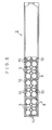
- a main wave-absorber body 1 is made of a material or a construction that can float in a water surface and is formed as a hollow-box structure using a material which is highly water-proof or which is treated to be water-proof.
- the pipes 10 may be made of, for example, a low-cost synthetic resin material such as PVC. Because the specific gravity of the synthetic resin material itself is small enough for it to float on water, the main wave-absorber body 1 has a satisfactory buoyancy. In addition, since the resin is formed into pipes, a large volume of air is sealed inside the chambers 9. Consequently, the main wave-absorber body 1 has high buoyancy. Furthermore, because the floating body is composed of the synthetic resin pipes 10, it is highly resistive to corrosion by water. In addition, replacement of the body can be carried out easily.
- a low-cost synthetic resin material such as PVC.
- a supporting float can also be provided as shown in Fig. 3.
- the supporting float comprises two synthetic resin pipes 10 wrapped around with a belt 13 and thereby fixed to a frame body portion 12 of the body 1, which is in the form of an H-shaped steel.
- the belt 13 for fixing the pipes 10 on an upper part (or upper and lower parts) of the frame body portion 12 is in close contact in an intermediate portion thereof with the outer peripheries of the pipes 10, while the ends of the belt are fixed to the frame body portion 12 via bolts 14.
- the pipes 10 are mounted so that they will not easily detach from the frame body portion 12.
- Employing such a fixing means for the external pipes 10 makes it easy to provide the main wave-absorber body 1 with satisfactory buoyancy, even if the buoyancy provided by the pipes 10 mounted inside the body 1 is insufficient.
- the removal and mounting of the external pipes 10 is very easy.
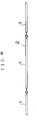
- a traction member 2 is shown in Fig. 4, where it can be seen that it comprises sealed pipe bodies 5 in suitable lengths, connected in such manner that they can pivot relative to each other.
- the sealed pipe bodies 5 are shown again in Fig. 5, where it may be seen that a cap 51 is mounted at each end of each pipe and welded thereto to close the pipe so that its interior is hermetically sealed.
- a connection ring 52 is fixed to the cap 51.
- the sealed pipe bodies 5 are made of a high-tension material, with an epoxy base adhesive 54 (Fig. 6) coated on the inner surface thereof. Furthermore, as shown in Fig. 6, a plurality of high-tension members 53 are encased therein.
- the members 53 may, for example, be wire ropes, piano wires, alamide fibers, carbon fibers or other high-tension metal wires or synthetic resin base fibers.
- the high-tension members 53 are coated or impregnated with, for example, an epoxy base adhesive 54 to integrate the members 53 altogether. At that time, the high-tension members 53 are also integrated with each sealed pipe body 5. In order to increase the tensile strength of the traction members 2, it is possible to bundle a suitable number of the sealed pipe bodies 5 into a bundle body 6 as shown in Fig. 7. It is then also possible to encase the bundle body 6 in a sealed pipe body 5A as shown by the ghost lines in Fig. 7.
- the traction members 2 being made from hermetically sealed pipes, are themselves provided with buoyancy. Since they also have a defined length, handling thereof is much easier. Compared to a conventional traction member, e.g. a chain, production costs of the traction members 2 can be greatly reduced. In addition, the strength thereof can also be improved significantly. Moreover, the functions of the main wave-absorber body 1 can be advantageously improved without reducing the buoyancy of the body 1. Of course, it is nevertheless possible to use conventional traction members such as chains in place of the above described members 2.
- Fig. 8 illustrates a floating wave absorber of a first embodiment of the invention, which comprises a connected structure body which floats in a substantially inverted-V shape in the water surface W.
- a pair of main wave-absorber bodies 1A and 1B have their opposed end portions pivotally interconnected by way of a hinge H.
- Traction members 2 and 2 have first ends connected to the free end portions of respective ones of the bodies 1A and 1B and second ends connected to respective anchors A installed on the water bottom B.
- a supporting body 16 is disposed between the main wave-absorber bodies 1A and 1B.
- the bodies 1A and 1B float in the water surface W in an upright manner, in a substantially inverted-V shaped configuration, with the traction members 2 extending substantially vertically.
- the apparatus it is possible to install the apparatus so that the spacing between the anchors A is so narrow as to approximate to the width of a fixed type breakwater.
- the supporting body 16 is used as a supplementary member if the buoyancy of the main wave-absorber bodies 1A and 1B is insufficient. It is formed substantially as a cone and is constructed to be floatable in water, like the bodies 1A and 1B. It is arranged so that it will not turn over in the water surface W, by forming it with a heavier portion 16a at its lower end. Consequently, if the buoyancy of the bodies 1A and 1B is sufficiently large, the supporting body 16 need not be used. However, the body 16 also serves the function of maintaining the bodies 1A and 1B in their inverted-V shaped arrangement. Therefore, it is preferable that the body 16 is located between the bodies 1A and 1B.
- the supporting body 16 when the supporting body 16 is located between the main wave-absorber bodies 1A and 1B, it is possible to connect the lower ends of the bodies 1A and 1B to the body 16 by stopper members 1a and 1b, as shown in ghost lines in Fig. 8. It is possible to replace the members 1a and 1b with a wire rope or the like, to connect the supporting body 16 to the bodies 1A and 1B. Alternatively the top portion of the body 16 may be connected to the hinge H.
- Fig. 9 shows how the bodies 1A and 1B receive the impact of waves.
- the bodies tilt in the downstream direction, to absorb the waves.
- the supporting body 16 comes into close contact with the inside of the body 1A as shown in Fig. 9, while preventing the bodies 1A and 1B from submerging in the water.
- the supporting body 16 also functions to cause the bodies 1A and 1B to recover their original upright state, as shown in Fig. 8, as soon as possible.
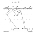
- Fig. 10 shows the manner of operation of the floating wave absorber of Figs. 8 and 9 when the waves become abnormally high due to a storm. At such times the wave absorbers can no longer satisfactorily absorb the waves, and might be destroyed in extreme conditions, were it not that the main wave-absorber bodies 1A and 1B are able to submerge so as to avoid such adverse effects, since the length of the traction members 2 is suitably preset. It is also possible to submerge the absorber by winding the traction members 2 up and down by remotely activating a revolving motor (not illustrated).
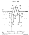
- Fig. 11 illustrates a secdnd embodiment of the present invention, in which four main wave-absorber bodies 1A, 1B, 17A and 17B are interconnected to form a floating wave absorber of improved capability.
- the opposed ends of the four bodies 1A, 1B, 17A and 17B are interconnected at hinges H.
- the traction members 2 are slidably engaged with rollers 18 disposed on one side surface of each main wave-absorber body 1A, 1B, 17A and 17B.
- the other ends of the traction members are connected to anchors A on the water bottom B.
- the main wave-absorber bodies 1A, 1B, 17A and 17B are connected with each other by extending one end portion of each traction member 2 over the rollers 18 disposed at the upper and lower outside ends of the bodies 1A, 1B, 17A and 17B.
- waves can be effectively absorbed in a wide range from the water surface W to substantially under the water.
- main wave-absorber bodies 1A, 1B, 17A and 17B are arranged upright in an inverted-V shape by means of the hinges.
- three or more main wave-absorber bodies may be interconnected and then coupled together by a hinge H.
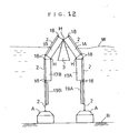
- Figs. 12 and 13 show a third embodiment of the invention, in which reflected-convection-preventive plates 19 are connected to main wave-absorber bodies 1A, 1B, 17A and 17B arranged according to the second embodiment, via hinges H.
- one end of each traction member 2 is connected to each plate 19.
- waves can be absorbed in a broader range.
- waves reflected from the water bottom, caused by waves being absorbed are attenuated at the reflected-convection-preventive plates 19, thereby improving the wave-absorbing effect.
- the construction and operation of the third embodiment is the same as the second embodiment, and the same reference numerals are used where appropriate.
- the main wave-absorber body is caused to float always in the surface of water by the wave forces. Therefore, more effective absorbtion of waves can be achieved.
- the effect of absorbing waves is adequately and quickly modified according to the water level and the sizes and velocities of the waves.
- the adverse effect of the waves is eliminated automatically by submergence of the main wave-absorber body.
- conventional fixed type breakwaters or mounted type wave-absorber blocks often cause environmental change or pollution because water flow is blocked between the water surface and the anchor, or water flow characteristics in the vicinity may be changed. However, with the present embodiments no such adverse effects are caused.
- installation work can be performed very easily and completed within a short time. Furthermore, installation costs can be greatly reduced.
- a supporting body formed as a cone may be interposed between the top portions of wave-absorber bodies arranged in an inverted-V shape.
- the main wave-absorber bodies can be made stable while floating in the water surface substantially in an inverted-V shape.
- reflected-convection-preventive plates may be connected to the main wave-absorber bodies.
- the present invention provides a floating wave absorber apparatus that is advantageous in economic performance, extremely easily and quickly installed, free from risks of being washed away by the abnormally high waves of a storm, and can effectively absorb waves by means of a simple structure.
Landscapes
- Engineering & Computer Science (AREA)
- General Engineering & Computer Science (AREA)
- Environmental & Geological Engineering (AREA)
- Ocean & Marine Engineering (AREA)
- Mechanical Engineering (AREA)
- Civil Engineering (AREA)
- Structural Engineering (AREA)
- Revetment (AREA)
Applications Claiming Priority (10)
| Application Number | Priority Date | Filing Date | Title |
|---|---|---|---|
| JP3263369A JPH07119453B2 (ja) | 1991-07-08 | 1991-07-08 | 浮消波装置 |
| JP263369/91 | 1991-07-08 | ||
| JP88182/91U | 1991-07-31 | ||
| JP88182/91 | 1991-07-31 | ||
| JP1991088182U JP2541952Y2 (ja) | 1991-07-31 | 1991-07-31 | 浮消波装置 |
| JP93810/91U | 1991-08-30 | ||
| JP9381091 | 1991-08-30 | ||
| JP93810/91 | 1991-08-30 | ||
| JP4112041A JPH07119454B2 (ja) | 1991-08-30 | 1992-03-19 | 浮消波装置 |
| JP112041/92 | 1992-03-19 |
Publications (3)
| Publication Number | Publication Date |
|---|---|
| EP0522838A2 EP0522838A2 (en) | 1993-01-13 |
| EP0522838A3 EP0522838A3 (en) | 1993-04-07 |
| EP0522838B1 true EP0522838B1 (en) | 1997-04-16 |
Family
ID=27467480
Family Applications (1)
| Application Number | Title | Priority Date | Filing Date |
|---|---|---|---|
| EP92306262A Expired - Lifetime EP0522838B1 (en) | 1991-07-08 | 1992-07-08 | Floating wave absorber |
Country Status (7)
| Country | Link |
|---|---|
| US (1) | US5294211A (enExample) |
| EP (1) | EP0522838B1 (enExample) |
| AU (2) | AU1952092A (enExample) |
| CA (1) | CA2073273A1 (enExample) |
| DE (1) | DE69219024T2 (enExample) |
| ES (1) | ES2103892T3 (enExample) |
| TW (1) | TW206274B (enExample) |
Families Citing this family (19)
| Publication number | Priority date | Publication date | Assignee | Title |
|---|---|---|---|---|
| DE9419810U1 (de) * | 1994-06-23 | 1995-05-04 | Vogeler, Horst, Ing.(grad.), 22041 Hamburg | Küstenschutzvorrichtung |
| DE4439773A1 (de) * | 1994-11-07 | 1996-05-15 | Doerpinghaus Ernst H | Strömungswiderstandselement für offene Gewässer |
| SE9603615L (sv) * | 1996-10-03 | 1997-11-10 | Fredrick Marelius | Förfarande och anordning för att erosionsskydda en kust |
| DE19716484A1 (de) * | 1997-04-19 | 1998-10-22 | Dirk Janisch | Kraft- und Strömungsminderer |
| DE19748175C2 (de) * | 1997-10-31 | 2001-07-12 | Clement Yacht Habour Systems G | Schwimmender Wellenbrecher |
| US6554534B1 (en) * | 1999-12-29 | 2003-04-29 | Donal Butterfield | Flexible structure and method for controlling the quality of liquids |
| US6305877B1 (en) * | 2000-03-06 | 2001-10-23 | The United States Of America As Represented By The Secretary Of The Navy | Breakwater/attenuation device for high speed vessel wake |
| US6976807B2 (en) * | 2000-06-23 | 2005-12-20 | Cabins To Castles, Inc. | Portable breakwater |
| US20030136325A1 (en) * | 2002-01-11 | 2003-07-24 | Wooley James W. | Barrier unit structures |
| US6935808B1 (en) * | 2003-03-17 | 2005-08-30 | Harry Edward Dempster | Breakwater |
| US6926480B2 (en) * | 2003-08-20 | 2005-08-09 | Zeftek, Inc. | Supplemental restraint for auto-rack railroad car restraint system |
| US7150592B2 (en) * | 2003-08-20 | 2006-12-19 | Zeftek, Inc. | Supplemental restraint for auto-rack railroad car restraint system |
| US7524140B2 (en) * | 2003-12-11 | 2009-04-28 | Elemental Innovation, Inc. | Wave attenuator and security barrier system—adjusting |
| CN102296566B (zh) * | 2011-06-03 | 2013-04-17 | 福建吉轮海洋投资有限公司 | 浮动消波系统 |
| JP5345727B1 (ja) | 2012-12-21 | 2013-11-20 | 加一郎 亀井 | 消波装置 |
| JP2014165337A (ja) | 2013-02-25 | 2014-09-08 | Rohm Co Ltd | 発光素子、発光素子パッケージおよび発光素子の製造方法 |
| US9850633B1 (en) * | 2016-08-30 | 2017-12-26 | Sergey Sharapov | Method and structure for dampening tsunami waves |
| CN107537698B (zh) * | 2017-09-26 | 2024-04-26 | 中国矿业大学 | 一种强化粗煤泥浮选装置 |
| CN113265985B (zh) * | 2021-04-06 | 2022-10-11 | 华北水利水电大学 | 一种消除渡槽水位波动的消波栅 |
Family Cites Families (11)
| Publication number | Priority date | Publication date | Assignee | Title |
|---|---|---|---|---|
| US436644A (en) * | 1890-09-16 | Floating breakwater | ||
| US3276210A (en) * | 1963-06-06 | 1966-10-04 | Robert L Stitt | Breakwater |
| GB1366680A (en) * | 1970-11-27 | 1974-09-11 | Debero Kogyo Co Ltd | Floating breakwater for attenuating waves |
| US3791150A (en) * | 1971-09-07 | 1974-02-12 | Debero Kogyo Co Ltd | Floating breakwater for attenuating seas |
| US3863455A (en) * | 1973-12-10 | 1975-02-04 | Richard Buckminster Fuller | Floatable breakwater |
| GB1529113A (en) * | 1976-06-15 | 1978-10-18 | Ryzewski W | Floating breakwater units |
| JPS5670310A (en) * | 1979-11-15 | 1981-06-12 | Gifu Plast Kogyo Kk | Floating wave dissipating levee |
| JPS58117112A (ja) * | 1981-12-28 | 1983-07-12 | Ryoichi Nonaka | 浮消波堤の重り |
| US4776724A (en) * | 1986-05-05 | 1988-10-11 | Nippon Kokan Kabushiki Kaisha | Floating wave dissipation structure |
| GB2204080A (en) * | 1987-05-02 | 1988-11-02 | Bukasa Ltd | Method and apparatus for retarding tidal flow |
| NL194474C (nl) * | 1990-04-18 | 2002-05-03 | Rob Van Den Haak | Werkwijze voor het dempen van watergolven en golfdemplichaam daarvoor. |
-
1992
- 1992-07-06 TW TW081105344A patent/TW206274B/zh active
- 1992-07-07 AU AU19520/92A patent/AU1952092A/en not_active Abandoned
- 1992-07-07 US US07/910,869 patent/US5294211A/en not_active Expired - Fee Related
- 1992-07-07 CA CA002073273A patent/CA2073273A1/en not_active Abandoned
- 1992-07-08 ES ES92306262T patent/ES2103892T3/es not_active Expired - Lifetime
- 1992-07-08 EP EP92306262A patent/EP0522838B1/en not_active Expired - Lifetime
- 1992-07-08 DE DE69219024T patent/DE69219024T2/de not_active Expired - Fee Related
-
1996
- 1996-01-08 AU AU40858/96A patent/AU4085896A/en not_active Abandoned
Also Published As
| Publication number | Publication date |
|---|---|
| CA2073273A1 (en) | 1993-01-09 |
| AU1952092A (en) | 1993-01-21 |
| AU4085896A (en) | 1996-03-14 |
| EP0522838A2 (en) | 1993-01-13 |
| DE69219024T2 (de) | 1997-11-20 |
| TW206274B (enExample) | 1993-05-21 |
| EP0522838A3 (en) | 1993-04-07 |
| US5294211A (en) | 1994-03-15 |
| DE69219024D1 (de) | 1997-05-22 |
| ES2103892T3 (es) | 1997-10-01 |
Similar Documents
| Publication | Publication Date | Title |
|---|---|---|
| EP0522838B1 (en) | Floating wave absorber | |
| KR102373405B1 (ko) | 파동 에너지를 전기 에너지로 변환하기 위한 장치 및 그러한 장치를 배치 위치에 배치하기 위한 프로세스 | |
| US3884042A (en) | Floating breakwater | |
| US5107784A (en) | Docking system for boats | |
| KR900005914B1 (ko) | 가요성 해양 플랫포옴(Flexible Offshore Platform) | |
| KR20200079216A (ko) | 풍력터빈과 관련 해상시설을 지원하기 위한 해상 플랫폼 | |
| US3953977A (en) | Device for damping waves | |
| US5429452A (en) | Floating break water structure | |
| US4642000A (en) | Anchoring system for concrete floating pier | |
| WO1987004590A1 (en) | Fish breeding device and way of constructing it | |
| US4135467A (en) | Means of protection against the shocks of ships coming alongside, particularly for platforms of the off-shore type | |
| US3444693A (en) | Water wave suppression device | |
| US5242243A (en) | Floating breakwater device | |
| US2972233A (en) | Wave breaking device | |
| KR102542325B1 (ko) | 부표식 파력 저감 장치 | |
| KR102373421B1 (ko) | 수상 부유체 연결 장치와 그 제조 방법 및 이를 구비하는 수상 부유체 | |
| JPH07247528A (ja) | 消波装置 | |
| JPH05125708A (ja) | 浮消波装置 | |
| JPS60144408A (ja) | 船舶侵入防護施設 | |
| JPS58146610A (ja) | 浮揚式防舷装置 | |
| JPH0112881B2 (enExample) | ||
| SU1331944A1 (ru) | Отбойное устройство | |
| SU763511A1 (ru) | Отбойное устройство | |
| JPH07119453B2 (ja) | 浮消波装置 | |
| JP3331446B2 (ja) | 浮桟橋 |
Legal Events
| Date | Code | Title | Description |
|---|---|---|---|
| PUAI | Public reference made under article 153(3) epc to a published international application that has entered the european phase |
Free format text: ORIGINAL CODE: 0009012 |
|
| AK | Designated contracting states |
Kind code of ref document: A2 Designated state(s): BE DE ES FR GB IT NL SE |
|
| PUAL | Search report despatched |
Free format text: ORIGINAL CODE: 0009013 |
|
| AK | Designated contracting states |
Kind code of ref document: A3 Designated state(s): BE DE ES FR GB IT NL SE |
|
| 17P | Request for examination filed |
Effective date: 19930927 |
|
| 17Q | First examination report despatched |
Effective date: 19950125 |
|
| GRAG | Despatch of communication of intention to grant |
Free format text: ORIGINAL CODE: EPIDOS AGRA |
|
| GRAH | Despatch of communication of intention to grant a patent |
Free format text: ORIGINAL CODE: EPIDOS IGRA |
|
| GRAH | Despatch of communication of intention to grant a patent |
Free format text: ORIGINAL CODE: EPIDOS IGRA |
|
| GRAA | (expected) grant |
Free format text: ORIGINAL CODE: 0009210 |
|
| AK | Designated contracting states |
Kind code of ref document: B1 Designated state(s): BE DE ES FR GB IT NL SE |
|
| REF | Corresponds to: |
Ref document number: 69219024 Country of ref document: DE Date of ref document: 19970522 |
|
| ITF | It: translation for a ep patent filed | ||
| PGFP | Annual fee paid to national office [announced via postgrant information from national office to epo] |
Ref country code: GB Payment date: 19970729 Year of fee payment: 6 |
|
| PGFP | Annual fee paid to national office [announced via postgrant information from national office to epo] |
Ref country code: SE Payment date: 19970731 Year of fee payment: 6 Ref country code: NL Payment date: 19970731 Year of fee payment: 6 Ref country code: FR Payment date: 19970731 Year of fee payment: 6 Ref country code: ES Payment date: 19970731 Year of fee payment: 6 Ref country code: DE Payment date: 19970731 Year of fee payment: 6 |
|
| PGFP | Annual fee paid to national office [announced via postgrant information from national office to epo] |
Ref country code: BE Payment date: 19970812 Year of fee payment: 6 |
|
| ET | Fr: translation filed | ||
| REG | Reference to a national code |
Ref country code: ES Ref legal event code: FG2A Ref document number: 2103892 Country of ref document: ES Kind code of ref document: T3 |
|
| PLBE | No opposition filed within time limit |
Free format text: ORIGINAL CODE: 0009261 |
|
| STAA | Information on the status of an ep patent application or granted ep patent |
Free format text: STATUS: NO OPPOSITION FILED WITHIN TIME LIMIT |
|
| 26N | No opposition filed | ||
| PG25 | Lapsed in a contracting state [announced via postgrant information from national office to epo] |
Ref country code: GB Free format text: LAPSE BECAUSE OF NON-PAYMENT OF DUE FEES Effective date: 19980708 |
|
| PG25 | Lapsed in a contracting state [announced via postgrant information from national office to epo] |
Ref country code: SE Free format text: LAPSE BECAUSE OF NON-PAYMENT OF DUE FEES Effective date: 19980709 Ref country code: ES Free format text: LAPSE BECAUSE OF THE APPLICANT RENOUNCES Effective date: 19980709 |
|
| PG25 | Lapsed in a contracting state [announced via postgrant information from national office to epo] |
Ref country code: BE Free format text: LAPSE BECAUSE OF NON-PAYMENT OF DUE FEES Effective date: 19980731 |
|
| BERE | Be: lapsed |
Owner name: NIIMURA MASATERU Effective date: 19980731 |
|
| PG25 | Lapsed in a contracting state [announced via postgrant information from national office to epo] |
Ref country code: NL Free format text: LAPSE BECAUSE OF NON-PAYMENT OF DUE FEES Effective date: 19990201 |
|
| GBPC | Gb: european patent ceased through non-payment of renewal fee |
Effective date: 19980708 |
|
| EUG | Se: european patent has lapsed |
Ref document number: 92306262.4 |
|
| PG25 | Lapsed in a contracting state [announced via postgrant information from national office to epo] |
Ref country code: FR Free format text: LAPSE BECAUSE OF NON-PAYMENT OF DUE FEES Effective date: 19990331 |
|
| NLV4 | Nl: lapsed or anulled due to non-payment of the annual fee |
Effective date: 19990201 |
|
| PG25 | Lapsed in a contracting state [announced via postgrant information from national office to epo] |
Ref country code: DE Free format text: LAPSE BECAUSE OF NON-PAYMENT OF DUE FEES Effective date: 19990501 |
|
| REG | Reference to a national code |
Ref country code: FR Ref legal event code: ST |
|
| REG | Reference to a national code |
Ref country code: ES Ref legal event code: FD2A Effective date: 20001102 |
|
| PG25 | Lapsed in a contracting state [announced via postgrant information from national office to epo] |
Ref country code: IT Free format text: LAPSE BECAUSE OF NON-PAYMENT OF DUE FEES Effective date: 20050708 |