EP0520517B1 - Housing for hermetic motor compressor - Google Patents
Housing for hermetic motor compressor Download PDFInfo
- Publication number
- EP0520517B1 EP0520517B1 EP92111005A EP92111005A EP0520517B1 EP 0520517 B1 EP0520517 B1 EP 0520517B1 EP 92111005 A EP92111005 A EP 92111005A EP 92111005 A EP92111005 A EP 92111005A EP 0520517 B1 EP0520517 B1 EP 0520517B1
- Authority
- EP
- European Patent Office
- Prior art keywords
- housing
- compressor
- drive shaft
- opening end
- longitudinal axis
- Prior art date
- Legal status (The legal status is an assumption and is not a legal conclusion. Google has not performed a legal analysis and makes no representation as to the accuracy of the status listed.)
- Expired - Lifetime
Links
- 239000012530 fluid Substances 0.000 claims description 20
- 230000007246 mechanism Effects 0.000 claims description 19
- 230000006835 compression Effects 0.000 claims description 12
- 238000007906 compression Methods 0.000 claims description 12
- 238000004519 manufacturing process Methods 0.000 description 8
- 238000003780 insertion Methods 0.000 description 6
- 230000037431 insertion Effects 0.000 description 6
- 238000010276 construction Methods 0.000 description 4
- 238000003754 machining Methods 0.000 description 4
- 230000002093 peripheral effect Effects 0.000 description 3
- 238000005219 brazing Methods 0.000 description 2
- 230000007547 defect Effects 0.000 description 2
- 230000000694 effects Effects 0.000 description 2
- 238000005299 abrasion Methods 0.000 description 1
- 230000004323 axial length Effects 0.000 description 1
- 230000003247 decreasing effect Effects 0.000 description 1
- 238000011161 development Methods 0.000 description 1
- 230000018109 developmental process Effects 0.000 description 1
- 238000013467 fragmentation Methods 0.000 description 1
- 238000006062 fragmentation reaction Methods 0.000 description 1
- 230000007257 malfunction Effects 0.000 description 1
- 230000013011 mating Effects 0.000 description 1
- 238000012986 modification Methods 0.000 description 1
- 230000004048 modification Effects 0.000 description 1
Images

Classifications
-
- F—MECHANICAL ENGINEERING; LIGHTING; HEATING; WEAPONS; BLASTING
- F04—POSITIVE - DISPLACEMENT MACHINES FOR LIQUIDS; PUMPS FOR LIQUIDS OR ELASTIC FLUIDS
- F04C—ROTARY-PISTON, OR OSCILLATING-PISTON, POSITIVE-DISPLACEMENT MACHINES FOR LIQUIDS; ROTARY-PISTON, OR OSCILLATING-PISTON, POSITIVE-DISPLACEMENT PUMPS
- F04C23/00—Combinations of two or more pumps, each being of rotary-piston or oscillating-piston type, specially adapted for elastic fluids; Pumping installations specially adapted for elastic fluids; Multi-stage pumps specially adapted for elastic fluids
- F04C23/008—Hermetic pumps
-
- F—MECHANICAL ENGINEERING; LIGHTING; HEATING; WEAPONS; BLASTING
- F04—POSITIVE - DISPLACEMENT MACHINES FOR LIQUIDS; PUMPS FOR LIQUIDS OR ELASTIC FLUIDS
- F04C—ROTARY-PISTON, OR OSCILLATING-PISTON, POSITIVE-DISPLACEMENT MACHINES FOR LIQUIDS; ROTARY-PISTON, OR OSCILLATING-PISTON, POSITIVE-DISPLACEMENT PUMPS
- F04C18/00—Rotary-piston pumps specially adapted for elastic fluids
- F04C18/02—Rotary-piston pumps specially adapted for elastic fluids of arcuate-engagement type, i.e. with circular translatory movement of co-operating members, each member having the same number of teeth or tooth-equivalents
-
- F—MECHANICAL ENGINEERING; LIGHTING; HEATING; WEAPONS; BLASTING
- F04—POSITIVE - DISPLACEMENT MACHINES FOR LIQUIDS; PUMPS FOR LIQUIDS OR ELASTIC FLUIDS
- F04C—ROTARY-PISTON, OR OSCILLATING-PISTON, POSITIVE-DISPLACEMENT MACHINES FOR LIQUIDS; ROTARY-PISTON, OR OSCILLATING-PISTON, POSITIVE-DISPLACEMENT PUMPS
- F04C2240/00—Components
- F04C2240/60—Shafts
- F04C2240/603—Shafts with internal channels for fluid distribution, e.g. hollow shaft
-
- Y—GENERAL TAGGING OF NEW TECHNOLOGICAL DEVELOPMENTS; GENERAL TAGGING OF CROSS-SECTIONAL TECHNOLOGIES SPANNING OVER SEVERAL SECTIONS OF THE IPC; TECHNICAL SUBJECTS COVERED BY FORMER USPC CROSS-REFERENCE ART COLLECTIONS [XRACs] AND DIGESTS
- Y10—TECHNICAL SUBJECTS COVERED BY FORMER USPC
- Y10S—TECHNICAL SUBJECTS COVERED BY FORMER USPC CROSS-REFERENCE ART COLLECTIONS [XRACs] AND DIGESTS
- Y10S417/00—Pumps
- Y10S417/902—Hermetically sealed motor pump unit
Definitions
- This invention relates to a fluid compressor and more particularly, to a motor driven fluid compressor having the compression and drive mechanisms within a hermetically sealed container.
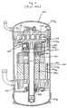
- FIGS 3 and 4 illustrate one and another prior art motor driven fluid compressors, respectively.
- the operation of each of the prior art compressors is well known in the art so that an explanation thereof is omitted.
- Figure 3 illustrates one motor driven fluid compressor having the compression and drive mechanisms within a hermetically sealed housing as disclosed in Japanese Utility Model Application Publication No. 63-105780 a similar compressor being disclosed in the FR-A-2 559 847 which forms the basis of the preamble of claim 1.
- compressor 200 includes hermetically sealed housing 210 which contains a compression mechanism, such as scroll type fluid compression mechanism 220 and drive mechanism 230 therein.
- Housing 210 includes cylindrical portion 210a, and first and second cup-shaped portions 210b and 210c.
- An opening end of first cup-shaped portion 210b is hermetically connected to an upper opening end of cylindrical portion 210a by, for example, brazing.
- An opening end of second cup-shaped portion 210c is hermetically connected to a lower opening end of cylindrical portion 210a by, for example, brazing.
- Scroll type fluid compression mechanism 220 includes fixed scroll 221 having circular end plate 221a and spiral element 221b which downwardly extends from circular end plate 221a.
- Circular end plate 221a of fixed scroll 221 is fixedly disposed within first cup-shaped portion 210b by, for example, forcible insertion.
- First inner block 240 is fixedly disposed within an upper region of cylindrical portion 210a by, for example, forcible insertion and is fixedly connected to circular end plate 221a of fixed scroll 221 by a plurality of bolts 250.
- Scroll type fluid compression mechanism 220 further includes orbiting scroll 222 having circular end plate 222a and spiral element 222b which upwardly extends from circular end plate 222a.
- Spiral element 221b of fixed scroll 221 interfits with spiral element 222b of orbiting scroll 222 with an angular and radial offset.
- Circular end plate 222a of orbiting scroll 222 is radially slidably disposed on an upper end surface of first inner block 240.
- Drive mechanism 230 includes drive shaft 231 and motor 232 surrounding drive shaft 231.
- Drive shaft 231 includes pin member 231a which upwardly extends from and is integral with an upper end of drive shaft 231.
- the axis of pin member 231a is offset from the axis of drive shaft 231, and pin member 231a is operatively connected to circular end plate 222a of orbiting scroll 222.
- Rotation preventing mechanism 260 is disposed between first inner block 240 and circular end plate 222a of orbiting scroll 222 so that orbiting scroll 222 only orbits during rotation of drive shaft 231.
- First inner block 240 includes first central opening 241 within which bearing 270 is fixedly disposed so as to rotatably support an upper end portion of drive shaft 231.
- Second inner block 280 axially spaced from first inner block 240 is fixedly disposed within a lower region of cylindrical portion 210a of housing 210 by, for example, forcible insertion.
- Second inner block 280 includes second central opening 281 within which bearing 290 is fixedly disposed so as to rotatably support a lower end portion of drive shaft 231.
- Motor 232 includes annular-shaped rotor 232a fixedly surrounding an exterior surface of drive shaft 231 and annular-shaped stator 232b surrounding rotor 232a with a radial air gap.
- Stator 232b are fixedly sandwiched by first and second inner blocks 240 and 280.
- first and second inner blocks 240 and 280 and cylindrical portion 210a of housing 210 are separately prepared before assembling the compressor. Therefore, as far as the above elements are prepared by a normal precise machining manner, it is difficult to obtain the compressor where the longitudinal axis of first central opening 241 of first inner block 210 and the longitudinal axis of second central opening 281 of second inner block 280, and the longitudinal axis of drive shaft 231 and the longitudinal axis of cylindrical portion 210a of housing 210 are easily and precisely aligned.
- an exterior surface of drive shaft 231 non-uniformly contacts to an inner peripheral surface of the inner ring of bearings 270 and 290, thereby causing fragmentation of the exterior surface of drive shaft 231 and damage of bearings 270 and 290 during operation of the compressor. This causes malfunction of the compressor. Furthermore, non-uniform radial air gap is created between rotor 232a and stator 232b of motor 232, thereby causing a decrease in efficiency of motor 232.
- Japanese Patent Application Publication No. 1-237376 discloses another motor driven fluid compressor having the compression and drive mechanisms within a hermetically sealed housing as illustrated in Figure 4.
- the same numerals are used to denote the substantial same elements shown in Figure 3.
- compressor 300 includes inner block 340 having generally circular disc-shaped portion 341 which is fixedly disposed within cylindrical portion 210a of housing 210 by, for example, forcible insertion.
- Inner block 340 includes central bore 342 formed through circular disc-shaped portion 341.
- Annular projection 343 downwardly projects from a lower peripheral end surface of a central bore 342, and terminates at a location which is a midway of cylindrical portion 210a.
- a plurality of curved plate-shaped projections 344 downwardly project from the lower end surface of a peripheral region of circular disc-shaped portion 341, and terminate at a location which is the midway of cylindrical portion 210a.
- An upper end portion of drive shaft 231 passes through central bore 342 and annular projection 343, and is rotatably supported by bearing 270 fixedly disposed within central bore 342 and a pair of plain bearings 343a and 343b fixedly disposed within annular projection 343.
- Annular-shaped rotor 232a fixedly surrounds an exterior surface of drive shaft 231.
- Annular stator 232b of motor 232 is fixedly connected to curved plate-shaped projections 344 by a plurality of corresponding blots 345.
- drive shaft 231 is rotatably and solely supported by inner block 340. Therefore, even though an axial length of central bore 342 of inner block 340 is relatively large, the excessive radial thrust force acts on bearings 270, 343a and 343b in a severe operating condition of the compressor in comparison with the prior art compressor shown in Figure 3 where bearings 270 and 290 are axially spaced each other with a sufficiently long distance. This causes unfavorable abrasion of bearings 270, 343a and 343b, thereby decreasing the life thereof.
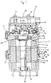
- Figure 1 illustrates a motor driven fluid compressor in accordance with a first embodiment of the present invention.
- compressor 10 includes housing 11 which contains a compression mechanism, such as scroll type fluid compression mechanism 20 and drive mechanism 30 therein.
- Housing 11 includes cylindrical portion 11a, and first and second cup-shaped portions 11b and llc.
- An opening end of first cup-shaped portion 11b is releasably and hermetically connected to an upper opening end of cylindrical portion 11a by a plurality of bolts 12.
- An opening end of second cup-shaped portion llc is releasably and hermetically connected to a lower opening end of cylindrical portion 11a by a plurality of bolts 13.
- Scroll type fluid compression mechanism 20 includes fixed scroll 21 having circular end plate 21a and spiral element 21b which downwardly extends from circular end plate 21a.
- Circular end plate 21a of fixed scroll 21 is fixedly disposed within first cup-shaped portion 11b by a plurality of bolts 14.
- Inner block 23 radially inwardly extends from and is integral with the upper opening end of cylindrical portion 11a of housing 11.
- Scroll type fluid compression mechanism 20 further includes orbiting scroll 22 having circular end plate 22a and spiral element 22b which upwardly extends from circular end plate 22a.
- Spiral element 21b of fixed scroll 21 interfits with spiral element 22b of orbiting scroll 22 with an angular and radial offset.
- Drive mechanism 30 includes drive shaft 31 and motor 32 surrounding drive shaft 31.
- Drive shaft 31 includes pin member 31a which upwardly extends from and is integral with an upper end of drive shaft 31.
- the axis of pin member 31a is offset from the axis of drive shaft 31, and pin member 31a is operatively connected to circular end plate 22a of orbiting scroll 22.
- Rotation preventing mechanism 24 is disposed between inner block 23 and circular end plate 22a of orbiting scroll 22 so that orbiting scroll 22 only orbits during rotation of drive shaft 31.
- Inner block 23 includes first central hole 23a of which the longitudinal axis is concentric with the longitudinal axis of cylindrical portion 11a.
- Bearing 25 is fixedly disposed within first central hole 23a so as to rotatably support an upper end portion of drive shaft 31.
- Second cup-shaped portion 11c includes second central hole 26 of which the longitudinal axis is concentric with the longitudinal axis of second cup-shaped portion 11c.
- Bearing 27 is fixedly disposed within second central hole 26 so as to rotatably support a lower end portion of drive shaft 31.
- Motor 32 includes annular-shaped rotor 32a fixedly surrounding an exterior surface of drive shaft 31 and annular-shaped stator 32b surrounding rotor 32a with a radial air gap.
- Stator 32b axially extends along a lower opening end region of cylindrical portion 11a and an opening end region of second cup-shaped portion 11c.
- a lower half portion of stator 32b is fixedly disposed within the opening end region of second cup-shaped portion 11c by, for example, forcible insertion.
- First annular cut-out section 28 is formed at an inner periphery of the lower opening end surface of cylindrical portion 11a of housing 11. Consequently, first annular projection 28a is formed at an outer periphery of the lower opening end surface of cylindrical portion 11a.
- the longitudinal axis of an inner periphery of first annular projection 28a is concentric with the longitudinal axis of cylindrical portion 11a.
- Second annular cut-out section 29 is formed at an outer periphery of the opening end surface of second cup-shaped portion 11c of housing 11. Consequently, second annular projection 29a is formed at an inner periphery of the opening end surface of second cup-shaped portion 11c.
- the longitudinal axis of an outer periphery of second annular projection 29a is concentric with the longitudinal axis of second cup-shaped portion 11c.
- O-ring seal element 33 is disposed at a bottom end surface of first annular cut-out section 28 to seal the mating surfaces of first annular cut-out section 28 and second annular projection 29a.
- the longitudinal axis of first central hole 23a of inner block 23 can be easily and precisely aligned with the longitudinal axis of cylindrical portion 11a of housing 11 by a normal machining manner because that inner block 23 and cylindrical portion 11a are formed in one body.
- the longitudinal axis of second central hole 26 of second cup-shaped portion 11c can be easily and precisely aligned with the longitudinal axis of second cup-shaped portion 11c by a normal machining manner because second central hole 26 is formed at a bottom end region of second cup-shaped portion 11c.
- cylindrical portion 11a and second cup-shaped portion 11c are easily and precisely connected by a well-known joint mechanism, such as a faucet joint.
- the longitudinal axis of first and second central holes 23a and 26, and the longitudinal axis of drive shaft 31, the longitudinal axis of cylindrical portion 11a and the longitudinal axis of second cup-shaped portion llc can be easily and precisely aligned without complicated manufacturing process of the compressor.
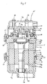
- Figure 2 illustrates a motor driven fluid compressor in accordance with a second embodiment of the present invention.
- an upper half portion of stator 32b is fixedly disposed within the lower opening end region of cylindrical portion 11a by, for example, forcible insertion.
- Other Features and aspects of this embodiment have been described in the first embodiment so that an explanation thereof is omitted.
- an effect of this embodiment is similar to the effect of the first embodiment so that an explanation thereof is also omitted.
Landscapes
- Engineering & Computer Science (AREA)
- Mechanical Engineering (AREA)
- General Engineering & Computer Science (AREA)
- Rotary Pumps (AREA)
- Applications Or Details Of Rotary Compressors (AREA)
Applications Claiming Priority (2)
| Application Number | Priority Date | Filing Date | Title |
|---|---|---|---|
| JP1991057942U JP2596301Y2 (ja) | 1991-06-28 | 1991-06-28 | 流体圧縮機 |
| JP57942/91U | 1991-06-28 |
Publications (2)
| Publication Number | Publication Date |
|---|---|
| EP0520517A1 EP0520517A1 (en) | 1992-12-30 |
| EP0520517B1 true EP0520517B1 (en) | 1996-08-28 |
Family
ID=13070093
Family Applications (1)
| Application Number | Title | Priority Date | Filing Date |
|---|---|---|---|
| EP92111005A Expired - Lifetime EP0520517B1 (en) | 1991-06-28 | 1992-06-29 | Housing for hermetic motor compressor |
Country Status (7)
| Country | Link |
|---|---|
| US (1) | US5374166A (ja) |
| EP (1) | EP0520517B1 (ja) |
| JP (1) | JP2596301Y2 (ja) |
| KR (1) | KR100192693B1 (ja) |
| AU (1) | AU643389B2 (ja) |
| CA (1) | CA2072685C (ja) |
| DE (1) | DE69213116T2 (ja) |
Families Citing this family (11)
| Publication number | Priority date | Publication date | Assignee | Title |
|---|---|---|---|---|
| JPS5676798A (en) * | 1979-11-27 | 1981-06-24 | Tlv Co Ltd | Bucket type steam trap |
| JP3078369B2 (ja) * | 1991-10-24 | 2000-08-21 | サンデン株式会社 | 圧縮機 |
| JP3614694B2 (ja) * | 1999-01-22 | 2005-01-26 | 松下電器産業株式会社 | 電動機直結駆動軸の両持ち軸受構造の与圧方法および装置とそれらを用いた密閉型圧縮機 |
| US6247909B1 (en) | 1999-08-18 | 2001-06-19 | Scroll Technologies | Bearing assembly for sealed compressor |
| US6280155B1 (en) | 2000-03-21 | 2001-08-28 | Tecumseh Products Company | Discharge manifold and mounting system for, and method of assembling, a hermetic compressor |
| US6682327B2 (en) * | 2001-02-26 | 2004-01-27 | Scroll Technologies | Method of aligning scroll compressor components |
| US20060159579A1 (en) * | 2005-01-20 | 2006-07-20 | Skinner Robin G | Motor-compressor unit mounting arrangement for compressors |
| US7841845B2 (en) | 2005-05-16 | 2010-11-30 | Emerson Climate Technologies, Inc. | Open drive scroll machine |
| US7878775B2 (en) * | 2008-01-17 | 2011-02-01 | Bitzer Kuhlmaschinenbau Gmbh | Scroll compressor with housing shell location |
| FR2933322B1 (fr) * | 2008-07-02 | 2010-08-13 | Adel | Procede de fabrication de virole pour compresseur a spirales |
| US8974197B2 (en) * | 2010-02-16 | 2015-03-10 | Halla Visteon Climate Control Corporation | Compact structure for an electric compressor |
Family Cites Families (11)
| Publication number | Priority date | Publication date | Assignee | Title |
|---|---|---|---|---|
| JPS5222205U (ja) * | 1975-08-05 | 1977-02-17 | ||
| JPS56156491A (en) * | 1980-05-07 | 1981-12-03 | Sanden Corp | Scroll type compressor equipped with electromagnetic clutch |
| JPS57146085A (en) * | 1981-03-03 | 1982-09-09 | Sanden Corp | Scroll type fluid apparatus |
| JPS5865985A (ja) * | 1981-10-12 | 1983-04-19 | Sanden Corp | 流体装置 |
| US4552518A (en) * | 1984-02-21 | 1985-11-12 | American Standard Inc. | Scroll machine with discharge passage through orbiting scroll plate and associated lubrication system |
| JPH0217196Y2 (ja) * | 1984-12-14 | 1990-05-14 | ||
| JPS61182482A (ja) * | 1985-02-06 | 1986-08-15 | Shin Meiwa Ind Co Ltd | スクロ−ル形流体機械 |
| JPS63235683A (ja) * | 1987-03-20 | 1988-09-30 | Sanden Corp | スクロ−ル型流体装置 |
| JPH0216071Y2 (ja) * | 1987-06-16 | 1990-05-01 | ||
| JPH0218879A (ja) * | 1988-07-05 | 1990-01-23 | Okazaki Seisakusho:Kk | ハーメチック端子 |
| JP2618018B2 (ja) * | 1988-09-14 | 1997-06-11 | 富士通株式会社 | 文字認識装置 |
-
1991
- 1991-06-28 JP JP1991057942U patent/JP2596301Y2/ja not_active Expired - Lifetime
-
1992
- 1992-06-27 KR KR1019920011417A patent/KR100192693B1/ko not_active IP Right Cessation
- 1992-06-29 DE DE69213116T patent/DE69213116T2/de not_active Expired - Lifetime
- 1992-06-29 AU AU19301/92A patent/AU643389B2/en not_active Expired
- 1992-06-29 EP EP92111005A patent/EP0520517B1/en not_active Expired - Lifetime
- 1992-06-29 CA CA002072685A patent/CA2072685C/en not_active Expired - Lifetime
-
1994
- 1994-01-04 US US08/177,696 patent/US5374166A/en not_active Expired - Lifetime
Also Published As
| Publication number | Publication date |
|---|---|
| EP0520517A1 (en) | 1992-12-30 |
| DE69213116D1 (de) | 1996-10-02 |
| CA2072685C (en) | 1998-07-07 |
| US5374166A (en) | 1994-12-20 |
| KR930000834A (ko) | 1993-01-15 |
| AU643389B2 (en) | 1993-11-11 |
| JPH051886U (ja) | 1993-01-14 |
| KR100192693B1 (ko) | 1999-06-15 |
| CA2072685A1 (en) | 1992-12-29 |
| JP2596301Y2 (ja) | 1999-06-14 |
| AU1930192A (en) | 1993-01-07 |
| DE69213116T2 (de) | 1997-02-20 |
Similar Documents
| Publication | Publication Date | Title |
|---|---|---|
| AU771839B2 (en) | Scroll compressor | |
| EP0479412B1 (en) | Oldham coupling for scroll compressor | |
| US5938417A (en) | Scroll type fluid machine having wraps formed of circular arcs | |
| US5407335A (en) | Non-orbiting scroll mounting arrangements for a scroll machine | |
| US5873710A (en) | Motor spacer for hermetic motor-compressor | |
| EP0756088B1 (en) | Scroll compressor | |
| KR100734699B1 (ko) | 스크롤압축기부품의 정렬방법 | |
| KR100220527B1 (ko) | 모터 구동 유체 압축기의 조립방법 | |
| KR100916554B1 (ko) | 올덤 커플링을 위한 클리어런스를 가진 스크롤 압축기 | |
| EP0520517B1 (en) | Housing for hermetic motor compressor | |
| EP0106288B1 (en) | Scroll type compressor | |
| GB2353334A (en) | Bearing assembly mounting for a sealed compressor | |
| US5474431A (en) | Scroll machine having discharge port inserts | |
| EP0400951B1 (en) | Axial sealing mechanism for a scroll type compressor | |
| EP1096150B1 (en) | Scroll machine | |
| EP0539239B1 (en) | Motor driven fluid compressor | |
| EP0295664B1 (en) | Compressor | |
| US5447415A (en) | Motor driven fluid compressor within hermetic housing | |
| JP3951349B2 (ja) | スクロール圧縮機 | |
| EP0373876B1 (en) | Hermetically sealed scroll type refrigerant compressor | |
| US20020102175A1 (en) | Scroll compressor | |
| JPH0874755A (ja) | スクロール型無給油式流体機械 | |
| JPH06272678A (ja) | 回転式スクロ−ル圧縮機 | |
| JPH09177687A (ja) | 電動式流体機械 | |
| JP2005188488A (ja) | スクロールコンプレッサ |
Legal Events
| Date | Code | Title | Description |
|---|---|---|---|
| PUAI | Public reference made under article 153(3) epc to a published international application that has entered the european phase |
Free format text: ORIGINAL CODE: 0009012 |
|
| AK | Designated contracting states |
Kind code of ref document: A1 Designated state(s): DE FR GB IT SE |
|
| 17P | Request for examination filed |
Effective date: 19921224 |
|
| 17Q | First examination report despatched |
Effective date: 19940715 |
|
| GRAG | Despatch of communication of intention to grant |
Free format text: ORIGINAL CODE: EPIDOS AGRA |
|
| GRAH | Despatch of communication of intention to grant a patent |
Free format text: ORIGINAL CODE: EPIDOS IGRA |
|
| GRAA | (expected) grant |
Free format text: ORIGINAL CODE: 0009210 |
|
| GRAH | Despatch of communication of intention to grant a patent |
Free format text: ORIGINAL CODE: EPIDOS IGRA |
|
| AK | Designated contracting states |
Kind code of ref document: B1 Designated state(s): DE FR GB IT SE |
|
| REF | Corresponds to: |
Ref document number: 69213116 Country of ref document: DE Date of ref document: 19961002 |
|
| ET | Fr: translation filed | ||
| ITF | It: translation for a ep patent filed | ||
| PLBE | No opposition filed within time limit |
Free format text: ORIGINAL CODE: 0009261 |
|
| STAA | Information on the status of an ep patent application or granted ep patent |
Free format text: STATUS: NO OPPOSITION FILED WITHIN TIME LIMIT |
|
| 26N | No opposition filed | ||
| REG | Reference to a national code |
Ref country code: GB Ref legal event code: IF02 |
|
| PGFP | Annual fee paid to national office [announced via postgrant information from national office to epo] |
Ref country code: FR Payment date: 20110621 Year of fee payment: 20 Ref country code: SE Payment date: 20110613 Year of fee payment: 20 |
|
| PGFP | Annual fee paid to national office [announced via postgrant information from national office to epo] |
Ref country code: GB Payment date: 20110629 Year of fee payment: 20 |
|
| PGFP | Annual fee paid to national office [announced via postgrant information from national office to epo] |
Ref country code: IT Payment date: 20110623 Year of fee payment: 20 |
|
| PGFP | Annual fee paid to national office [announced via postgrant information from national office to epo] |
Ref country code: DE Payment date: 20110622 Year of fee payment: 20 |
|
| REG | Reference to a national code |
Ref country code: DE Ref legal event code: R071 Ref document number: 69213116 Country of ref document: DE |
|
| REG | Reference to a national code |
Ref country code: DE Ref legal event code: R071 Ref document number: 69213116 Country of ref document: DE |
|
| REG | Reference to a national code |
Ref country code: GB Ref legal event code: PE20 Expiry date: 20120628 |
|
| PG25 | Lapsed in a contracting state [announced via postgrant information from national office to epo] |
Ref country code: DE Free format text: LAPSE BECAUSE OF EXPIRATION OF PROTECTION Effective date: 20120630 |
|
| REG | Reference to a national code |
Ref country code: SE Ref legal event code: EUG |
|
| PG25 | Lapsed in a contracting state [announced via postgrant information from national office to epo] |
Ref country code: GB Free format text: LAPSE BECAUSE OF EXPIRATION OF PROTECTION Effective date: 20120628 |