EP0519148A2 - Procédé et dispositif de réduction du contenu liquide de gâteau de filtre provenant d'un filtre de plaques - Google Patents
Procédé et dispositif de réduction du contenu liquide de gâteau de filtre provenant d'un filtre de plaques Download PDFInfo
- Publication number
- EP0519148A2 EP0519148A2 EP91811004A EP91811004A EP0519148A2 EP 0519148 A2 EP0519148 A2 EP 0519148A2 EP 91811004 A EP91811004 A EP 91811004A EP 91811004 A EP91811004 A EP 91811004A EP 0519148 A2 EP0519148 A2 EP 0519148A2
- Authority
- EP
- European Patent Office
- Prior art keywords
- filter
- fluid
- liquid
- filter cake
- plate filter
- Prior art date
- Legal status (The legal status is an assumption and is not a legal conclusion. Google has not performed a legal analysis and makes no representation as to the accuracy of the status listed.)
- Granted
Links
Images

Classifications
-
- B—PERFORMING OPERATIONS; TRANSPORTING
- B01—PHYSICAL OR CHEMICAL PROCESSES OR APPARATUS IN GENERAL
- B01D—SEPARATION
- B01D37/00—Processes of filtration
- B01D37/02—Precoating the filter medium; Addition of filter aids to the liquid being filtered
-
- B—PERFORMING OPERATIONS; TRANSPORTING
- B01—PHYSICAL OR CHEMICAL PROCESSES OR APPARATUS IN GENERAL
- B01D—SEPARATION
- B01D25/00—Filters formed by clamping together several filtering elements or parts of such elements
- B01D25/22—Cell-type filters
- B01D25/26—Cell-type stack filters
-
- B—PERFORMING OPERATIONS; TRANSPORTING
- B01—PHYSICAL OR CHEMICAL PROCESSES OR APPARATUS IN GENERAL
- B01D—SEPARATION
- B01D25/00—Filters formed by clamping together several filtering elements or parts of such elements
- B01D25/28—Leaching or washing filter cakes in the filter handling the filter cake for purposes other than regenerating
- B01D25/282—Leaching or washing filter cakes in the filter handling the filter cake for purposes other than regenerating for drying
- B01D25/284—Leaching or washing filter cakes in the filter handling the filter cake for purposes other than regenerating for drying by gases or by heating
Definitions
- the invention relates to a method for reducing the liquid content of the filter cake obtained in a plate filter.
- US Pat. Nos. 3,608,734, 4,869,834 and European patent applications 0 032 829, 0 304 597 describe a plate filter with a plate stack which has a number of plates which can be separated from one another. There is a filter belt between each two plates, through which an inlet chamber on the underside of the upper plate is delimited from an outlet chamber on the upper side of the plate arranged below.
- the liquid to be cleaned e.g. Rolling oil of an aluminum rolling mill with a temperature of 40 to 70 degrees C is fed to the inlet chamber, from where the liquid then flows through a section of the filter belt into the outlet chamber. All inlet chambers are connected to a common distributor and all outlet chambers are connected to a common collector.
- a filter belt transport device is provided for each filter belt in order to periodically replace a used filter belt section with a fresh filter belt section.
- the plates of the plate stack are separated from one another.
- a device is provided, which also has the task of pressing the plates together after the transport of the filter belt so that they clamp a new filter belt section between the edges of the inlet chamber and the outlet chamber. Clamping the filter band creates a seal.
- a circumferential groove near the edge of the plate catches any leakage fluid, which is then sucked off by a vacuum.
- such a filter aid becomes granular or powdered form of the liquid and applied as a precoat to the filter belt sections located in the plate filter.
- the grain size of the absorption or adsorption material and the pore size of the filter belt are selected such that the granular or powdery filter aid remains on the filter belt sections.
- the filter aid is exhausted and the filter belt requires an excessively high pressure to pump the liquid through the absorption of contaminants, the precoat and the filter belt must be replaced.
- the inlet chambers and the outlet chambers must be emptied. This is usually done using compressed air that is introduced into the inlet chambers. This compressed air, which has approximately ambient temperature, presses the liquid located in the respective inlet chamber through the precoat and the filter belt section into the outlet chamber. From there, the residual liquid driven by the compressed air can flow to the common outlet and on to the tank for cleaned liquid.
- the plate filter can also be emptied by applying a vacuum to the outlet chambers. The use of an injector is known for this purpose.
- the filter plates are first separated from one another, whereupon the filter belt transport device is actuated.
- the filter belt sections with the dirty precoat layers are transported out of the plate filter and fresh filter belt sections are drawn in, whereupon the plates are pressed together again so that they clamp the new filter belt sections.
- the dirty precoat not only contains contaminants, but usually also has a relatively high liquid content.
- the liquid content of the filter cake partially de-oiled with compressed air, is about 30 to 50 percent by weight. This liquid content has so far been accepted. However, it is a problem in two respects. On the one hand, this causes a loss of fluid; on the other hand, the liquid content of the filter cake creates considerable disposal problems. For example, filter cake with a high mineral oil content should not be stored in a landfill, but must e.g. be disposed of in an incinerator, which is associated with considerable costs.
- this object is achieved in that the filter cake is treated with a fluid which improves the removal of liquid from the filter cake before it is removed within the plate filter.
- the choice of fluid depends on various factors, e.g. the type of liquid that has been cleaned with the plate filter, the type of filter aid, the type of filter belt, etc. Different fluids can promote fluid withdrawal in different ways, e.g. by changing the viscosity, by changing the adsorption or absorption properties of the filter aid, by the dissolving action, etc. However, the physical and / or chemical processes are not clear in all cases.
- the fluid contained in the filter cake reduces the liquid before the filter cake is removed from the plate filter. The liquid thus recovered can usually be reused.
- the filter cake when removed from the plate filter, has a greatly reduced and in some cases even practically completely reduced liquid content. This makes the disposal of the filter cake easier.
- the direction of flow of the fluid in the plate filter is preferably the same as in the filtration. This enables the implementation of the method without great expenditure on equipment, because essentially the same equipment as for the filtration can be used to reduce the liquid.
- the fluid in certain cases it is advantageous to bring the fluid to an elevated temperature, for example 60 to 300 degrees, preferably 150 to 250 degrees C, before being introduced into the plate filter. This heats up the filter cake so that the liquid contained therein has a lower viscosity and therefore flows out of the filter cake much more easily.
- the fluid used advantageously has a good absorption capacity for the liquid to be removed.
- the fluid is advantageously gaseous. This makes it possible to separate the extracted liquid and the fluid with little effort.
- a gaseous or a liquid fluid can be used.
- heated compressed air can be used as the fluid. Since compressed air is available in most industrial companies, only a small investment is required to carry out the process.
- a gas such as nitrogen or carbon dioxide is used as the fluid. This avoids the risk of explosion, especially when working at elevated temperatures becomes.
- the use of nitrogen, carbon dioxide or other inert gas is particularly advantageous if the liquid, eg rolling oil, has a low flash point in the filter cake.
- nitrogen is very suitable for removing rolling oil. Nitrogen is believed to have a good absorbing ability for rolling oil. However, it is quite conceivable that this also applies to other gases.
- the choice of the gas used depends not only on these properties, but also on the ease of its procurement and its cost at the location of the plate filter where it is used.
- a fluid in the form of a solvent can be used to reduce the liquid content of the filter cake.
- the use of steam as a fluid is also conceivable.
- the plate filter instead of pumping the fluid through the plate filter by applying pressure, it can also be pumped by applying a vacuum to the outlet of the plate filter.
- the generation of the negative pressure can e.g. done by an injector. Since injectors are relatively simple devices, the investment costs can be kept low. This is especially true when compressed air is not available and the expenses for a compressor system can be avoided.
- the fluid e.g. Nitrogen
- the fluid e.g. Nitrogen
- the invention also relates to an apparatus for performing the method.
- This device is characterized in that that the inlets to the inlet chambers can be connected to a fluid source via a valve. This enables the method to be carried out with little expenditure on equipment.
- a reservoir e.g. a pressure vessel may be provided to introduce fluid into the process as needed.
- a fluid pump can be provided to maintain the circulation.
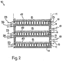
- a plate filter 10 is shown schematically in FIGS. 1 and 2.
- the plate filter 10 has a plate stack with a number of plates 11 that can be separated from one another. Between each two plates there is a filter belt section 13. Above the respective filter belt section 13 is the inlet chamber 15. The outlet chamber 17 is located below the filter belt 13. All inlet chambers 15 are connected via hoses 19 to a distributor 21 (FIG. 1). All outlet chambers 17 are connected to a collector 25 via hoses 23.
- the valves 58, 53, a distributor 24 and hoses 26 compressed air can be supplied to the inlet chambers 15, the liquid from the outlet chambers 17 (FIG. 2 ), the hoses 23, the collector 25 and the valves 36, 72 can flow into the tank 27.
- Line 29 leads from tank 27 for the liquid to be filtered to pump 31 and from there via valve 33 to distributor 21.
- Line 25 leads from collector 25 to valve 37.
- Valve 37 leads to tank 39 for the cleaned liquid.
- Tanks 39 and 27 are connected to one another by an overflow line 40.
- the reference number 41 indicates the line from the liquid user, e.g. from an aluminum rolling mill, referred to tank 27.
- the reference number 43 denotes the line from the tank 39 to the liquid user.
- the tank 45 contains the powdery or granular filter aid which is used to produce the precoat layers 47 (FIG. 2) on the filter belt 13.
- An agitator 49 is used to mix the powdery or granular filter aid with liquid.
- the suspension thus formed can then be pumped into the plate filter 10 via the lines 52, 29 to form the precoat layers 47 by means of the pump 51.
- FIGS. 1 and 2 essentially corresponds to the description of a known plate filter system, as was shown, for example, in US Pat. No. 3,608,734 or European Patent Application 0 132 829. For further details of such a system, reference can therefore be made to these publications.
- the fluid is supplied to the distributor 24 via the valve 53.
- a gas for example, can be used as the fluid which has the property of reducing the liquid content of the filter cake, for example by reducing the viscosity of the liquid. If a gas is thus heated by a fluid heater 55 to 60 to 300 degrees C and fed to the plate filter 10 via the valve 53, the heat causes the filter cake to heat up. The liquid still contained in the filter cake then loses viscosity and is therefore easily removed from the filter cake.
- heated compressed air can be used as the fluid.
- a line 57 with a valve 58 to the fluid heater 55 is therefore provided from the compressed air source 20.
- a gas e.g. Nitrogen or carbon dioxide.
- a line 60 with a valve 61 to the fluid heater 55 can therefore be provided from a source 59 for gas.
- nitrogen is often available as an inert gas.
- the liquid reduction essentially depends on four factors, namely the gas temperature, the flow rate, the time and the type of gas used.
- temperatures of 60 to 300 degrees C, preferably 150 to 250 degrees C, can be used depending on the requirements.
- a time of approximately 30 minutes down to approximately 5 minutes is to be expected as the treatment duration.
- the process can be optimized by selecting the appropriate parameters. It is also possible to work with a temperature curve. For example, the temperature can be lowered towards the end of the treatment period in order to cool the filter cake and the filter belt before removal from the plate filter.
- the filter cake cleaned with the described method can be disposed of more easily or, in many cases, can also be reused at least in part as a filter aid.
- a pump 65 can be provided.
- the circuit then leads from the outlet chambers 17 of the plate filter 10, the hoses 23, the valves 36, 71, the separator 69, e.g. Gas / liquid separator, line 70, pump 65, fluid heater 55, valve 53, manifold 24, and hoses 26 back to inlet chambers 15 of plate filter 10.
- a liquid e.g. a solvent
- a fluid tank 68 can be provided, from which a valve 66 is used to introduce the fluid into the process. It must of course be ensured that the fluid does not remain in the liquid to be cleaned.
- a suitable separator 69 e.g. Liquid / liquid separator provided. From the separator 69, the fluid reaches the fluid tank 68 via the pump 65. (In this case, the line 70 leads to the fluid tank 68 instead of a fluid heater 55). So there is also a fluid circulation here. The liquid separated from the filter cake is fed to the tank 27 via the line 74.
- the residual liquid contained therein after the filtering operation must be removed. This can be done by blowing out Compressed air or by suction. Compressed air from a compressed air source 20 can be used for blowing out, if one is provided.
- an injector 75 is shown, which can be connected to the outlet of the pump 31 via the valve 78. The suction connection of the injector 75 can be connected to the plate filter 10 via the valves 76, 32, 36 and the distributor 21 or collector 25, from which the residual liquid can then be conveyed into the tank 27 by the action of the injector. The closing of the valves 71, 72 prevents the intake of air.
- the floating, i.e. the formation of the precoat from filter aids begins after new filter belt sections 13 have been drawn into the plate filter 10.
- the valves 33, 36, 72 are open.
- the valves 37, 30 and 53 are closed.
- the pumps 31 and 51 are running.
- the pump 51 pumps the suspension contained in the tank 45 via the line 29, the open valve 33 and the distributor 21 into the chambers 15 of the plate filter 10, where the suspension is distributed over the filter belt sections 13.
- the liquid flows through the respective filter band section 13 into the outlet chamber 17 and from there via the hose 23, the collector 25, and the valves 36, 72 into the tank 27.
- the air initially contained in the plate filter 10 flows out of the inlet chambers 15 the hoses 26, the collector 24, the line 28 and the valve 30 into the tank 27, whereupon the valve 30 is closed.
- the tank 27 is vented via the overflow line 40, the tank 39 and the line 63.
- Valves 30, 33 and 37 are open during the filtering operation. Contaminated liquid from the tank 27 is pumped through the plate filter 10 by means of the pump 31. The cleaned one Liquid from the plate filter 10 flows via the line 35 and the opened valve 37 into the tank 39. In the filtering operation, too, filter aid is conveyed by the pump 51, for example intermittently, in metered amounts.
- the filtering operation is interrupted to replace precoat layers and filter belt sections.
- the liquid contained in the plate filter 10 must be drained. This is done, for example, by blowing compressed air out of the compressed air source 20.
- compressed air having normal temperature flows with a pressure of preferably 4 bar or higher through the distributor 24 and the hoses 26 into the inlet chamber 15 (FIG. 2) and presses the liquid present there through the precoat layers 47 and the filter belt sections 13 into the outlet chambers 17.
- Another way to draw off the residual liquid is to use a vacuum. If no compressed air source 20 is available, an injector 75 can therefore be provided.
- the pump 31 when running, the valve 33 is closed and the valve 78 is open, the liquid circuit from the tank 27 via the pump 31 and the injector 75 to the tank 27 generates a negative pressure which, when the valves 71, 72 are closed, via the open valves 76 , 36 and 32 sucks the residual liquid from the plate filter 10.
- the residual liquid reaches the tank 27 via the injector 75.
- the method according to the invention for reducing the liquid content of the filter cake obtained in a plate filter now provides that a fluid flows through the filter cake before it is removed within the plate filter 10, which fluid improves the removal of liquid from the filter cake.
- Hot compressed air for example, can be used as such a fluid.
- compressed air from the compressed air source 20 is fed into the plate filter 10 via the valve 58, the switched on fluid heater 55, the valve 53, the distributor 24 and the hoses 26.
- the heat causes the filter cake to heat up, which causes the remaining liquid to have a lower viscosity and is therefore expelled from the filter cake much better. Together with the air, the expelled liquid flows from the outlet chambers 17 (FIG.
- the ventilation of the tank 27 takes place via the overflow line 40, the tank 39 and the line 63.
- the possible working temperature of the fluid is limited in particular by three factors, namely the type of fluid used, the liquid which is to be separated from the filter cake and the material of the hoses 23, 26. In any case, it must be avoided that there is a risk of fire or explosion or that the hoses are damaged by the effects of temperature.
- inert gas from the source 59 can be supplied to the plate filter 10 via the valve 61, the fluid heater 55 and the valve 53. It is also possible to empty the plate filter with compressed air before introducing this fluid.
- valve 64 can be closed and the pump 65 can be switched on some time after the valve 61 has opened, that is to say when there is no more air in the system.
- a suitable separator 69 can be used for this purpose. If necessary, after the use of a liquid as a fluid to reduce the liquid content of the filter cake, a rinsing with a gaseous fluid can be carried out in order to remove residues of the liquid fluid.
- the filter cake (47) is still inside the plate filter (10) from a fluid, e.g. a gas with a temperature of 60 to 300 degrees C, which promotes the removal of liquid from the filter cake.
- a fluid e.g. a gas with a temperature of 60 to 300 degrees C
- the liquid content of around 30 to 50 percent contained in the filter cake can be almost completely removed and reused.
- the treated filter cake is largely free of liquid when removed from the plate filter and can therefore be disposed of more easily and cheaply than before. Reuse as a filter aid is also possible because the particles practically no longer stick together, but are almost back to their original condition.
- the particles are in turn able to form a highly porous filter cake. At least a part of the cleaned material can therefore be reused, so that the amount of waste material to be landfilled is greatly reduced.
Landscapes
- Chemical & Material Sciences (AREA)
- Chemical Kinetics & Catalysis (AREA)
- Filtration Of Liquid (AREA)
- Fats And Perfumes (AREA)
Applications Claiming Priority (2)
| Application Number | Priority Date | Filing Date | Title |
|---|---|---|---|
| CH1061/91 | 1991-04-10 | ||
| CH106191 | 1991-04-10 |
Publications (3)
| Publication Number | Publication Date |
|---|---|
| EP0519148A2 true EP0519148A2 (fr) | 1992-12-23 |
| EP0519148A3 EP0519148A3 (en) | 1993-11-24 |
| EP0519148B1 EP0519148B1 (fr) | 1998-04-01 |
Family
ID=4201541
Family Applications (1)
| Application Number | Title | Priority Date | Filing Date |
|---|---|---|---|
| EP91811004A Expired - Lifetime EP0519148B1 (fr) | 1991-04-10 | 1991-12-31 | Procédé de réduction du contenu huileux de gâteau de filtre provenant d'un filtre de plaques |
Country Status (4)
| Country | Link |
|---|---|
| EP (1) | EP0519148B1 (fr) |
| JP (1) | JPH05237309A (fr) |
| DE (1) | DE59108959D1 (fr) |
| ES (1) | ES2116282T3 (fr) |
Cited By (2)
| Publication number | Priority date | Publication date | Assignee | Title |
|---|---|---|---|---|
| CN112473243A (zh) * | 2020-12-18 | 2021-03-12 | 宁乡核工业热处理材料有限责任公司 | 一种劣化硝酸熔盐的净化系统及再生方法 |
| CN112535971A (zh) * | 2020-11-17 | 2021-03-23 | 中冶南方工程技术有限公司 | 适用高粘度轧制油过滤的助滤剂混合箱及过滤系统 |
Citations (3)
| Publication number | Priority date | Publication date | Assignee | Title |
|---|---|---|---|---|
| US1693417A (en) * | 1922-12-21 | 1928-11-27 | Justin F Wait | Filtering process |
| CH145968A (de) * | 1929-05-01 | 1931-03-31 | Chem Ind Basel | Verfahren zum Trocknen von Filterpressgut und heizbare Filterpresse zur Ausübung des Verfahrens. |
| GB488280A (en) * | 1937-11-30 | 1938-06-05 | Manor Engineering Company Ltd | Improvements in or relating to filter presses |
-
1991
- 1991-12-31 ES ES91811004T patent/ES2116282T3/es not_active Expired - Lifetime
- 1991-12-31 EP EP91811004A patent/EP0519148B1/fr not_active Expired - Lifetime
- 1991-12-31 DE DE59108959T patent/DE59108959D1/de not_active Expired - Fee Related
-
1992
- 1992-04-07 JP JP4113195A patent/JPH05237309A/ja active Pending
Patent Citations (3)
| Publication number | Priority date | Publication date | Assignee | Title |
|---|---|---|---|---|
| US1693417A (en) * | 1922-12-21 | 1928-11-27 | Justin F Wait | Filtering process |
| CH145968A (de) * | 1929-05-01 | 1931-03-31 | Chem Ind Basel | Verfahren zum Trocknen von Filterpressgut und heizbare Filterpresse zur Ausübung des Verfahrens. |
| GB488280A (en) * | 1937-11-30 | 1938-06-05 | Manor Engineering Company Ltd | Improvements in or relating to filter presses |
Cited By (3)
| Publication number | Priority date | Publication date | Assignee | Title |
|---|---|---|---|---|
| CN112535971A (zh) * | 2020-11-17 | 2021-03-23 | 中冶南方工程技术有限公司 | 适用高粘度轧制油过滤的助滤剂混合箱及过滤系统 |
| CN112473243A (zh) * | 2020-12-18 | 2021-03-12 | 宁乡核工业热处理材料有限责任公司 | 一种劣化硝酸熔盐的净化系统及再生方法 |
| CN112473243B (zh) * | 2020-12-18 | 2023-10-13 | 湖南中核热盐科技有限公司 | 一种劣化硝酸熔盐的净化系统及再生方法 |
Also Published As
| Publication number | Publication date |
|---|---|
| DE59108959D1 (de) | 1998-05-07 |
| ES2116282T3 (es) | 1998-07-16 |
| JPH05237309A (ja) | 1993-09-17 |
| EP0519148B1 (fr) | 1998-04-01 |
| EP0519148A3 (en) | 1993-11-24 |
Similar Documents
| Publication | Publication Date | Title |
|---|---|---|
| EP0537516A1 (fr) | Procédé pour le traitement de liquides de lavage à contre-courant provenant d'un filtre au lavage à contre-courant et dispositif du sédimentation pour liquides de lavage | |
| DE2451909A1 (de) | Anlage zum reinigen der innenwaende von kondensator-kuehlwasserrohren | |
| DE1764375B1 (de) | Verfahren zum entfernen radioaktiver fester stoffe aus einer verunreinigten fluessigkeit | |
| DE102004033328A1 (de) | Filter mit Feststoff-Resuspendierung | |
| DE3205377A1 (de) | Verfahren und vorrichtung zur kompressionsregenerierung flexibler poroeser materialien | |
| CH634757A5 (de) | Verfahren und vorrichtung zur abscheidung von schwebstoffen aus suspensionen durch absitz- und filterverfahren. | |
| EP0135208A2 (fr) | Procédé de séparation de levure de bouillons de culture et application de ce procédé | |
| DE2330200B2 (de) | Verfahren und vorrichtung zum abtrennen von oel oder schwebeteilchen aus emulsionen oder dispersionen | |
| EP0519148A2 (fr) | Procédé et dispositif de réduction du contenu liquide de gâteau de filtre provenant d'un filtre de plaques | |
| EP0630992A1 (fr) | Procédé pour nettoyer des pièces métalliques | |
| DE2909647A1 (de) | Verfahren und vorrichtung zur rueckgewinnung von energie aus gichtgas | |
| DE2323312C3 (de) | Verfahren und Vorrichtung zum Aufbereiten von bei der Behandlung von Flüssigkeiten beladenem Absorbermaterial | |
| DE3313943A1 (de) | Verfahren und vorrichtung zum kontinuierlichen austausch von in einem chemischen und/oder physikalischen vorgang, wie z. b. einem filter-, einem adsorptions- oder trockenvorgang, verbrauchten regenerierbaren kontaktmitteln, wie filtermaterialien, trockenmitteln, adsorbermaterialien oder katalysatoren | |
| DE3145667A1 (de) | Verfahren und vorrichtung zur kompressionsregenerierung flexibler filter-, oelabscheide- und/oder traegermaterialien | |
| EP0105225B1 (fr) | Procédé de nettoyage d'un élément de filtration pour les substances liquides et du dispositif de séparation renfermant cet élément | |
| DE322575C (de) | Absaugevorrichtung zum Herstellen grosser Koerper aus Papiermasse | |
| DE3136905C2 (fr) | ||
| DE2107760A1 (de) | Verfahren und Vorrichtung zum Filtern | |
| AT523844B1 (de) | Verfahren zur Aufbereitung einer mit Fremdstoffen beladenen Wischlösung | |
| DE4300493A1 (en) | Sludge filter - has closure blocks to be operated for rinsing to clean filter without interrupting the filtration | |
| DE69820979T2 (de) | Verfahren zur Regenerierung einer verunreinigten Flüssigkeit und Vorrichtung zur Durchführung des Verfahrens | |
| DE4224259A1 (de) | Reinigungsanlage | |
| DE2601732B2 (de) | Verfahren zum Spulen der Filterkammern eines Filteraggregates und Filteraggregat zur Durchführung dieses Verfahrens | |
| DE102017111637B3 (de) | Batchverfahren zur Konzentrierung von Inhaltsstoffen CO2-haltiger Flüssigkeiten und Vorrichtung hierzu | |
| EP0077411B1 (fr) | Procédé d'élimination de matières solides d'un liquide |
Legal Events
| Date | Code | Title | Description |
|---|---|---|---|
| PUAI | Public reference made under article 153(3) epc to a published international application that has entered the european phase |
Free format text: ORIGINAL CODE: 0009012 |
|
| AK | Designated contracting states |
Kind code of ref document: A2 Designated state(s): BE CH DE ES FR GB IT LI |
|
| PUAL | Search report despatched |
Free format text: ORIGINAL CODE: 0009013 |
|
| AK | Designated contracting states |
Kind code of ref document: A3 Designated state(s): BE CH DE ES FR GB IT LI |
|
| 17P | Request for examination filed |
Effective date: 19940520 |
|
| 17Q | First examination report despatched |
Effective date: 19940805 |
|
| GRAG | Despatch of communication of intention to grant |
Free format text: ORIGINAL CODE: EPIDOS AGRA |
|
| GRAH | Despatch of communication of intention to grant a patent |
Free format text: ORIGINAL CODE: EPIDOS IGRA |
|
| GRAH | Despatch of communication of intention to grant a patent |
Free format text: ORIGINAL CODE: EPIDOS IGRA |
|
| RAP1 | Party data changed (applicant data changed or rights of an application transferred) |
Owner name: INFRAMETAL ESTABLISHMENT |
|
| GRAA | (expected) grant |
Free format text: ORIGINAL CODE: 0009210 |
|
| AK | Designated contracting states |
Kind code of ref document: B1 Designated state(s): BE CH DE ES FR GB IT LI |
|
| PG25 | Lapsed in a contracting state [announced via postgrant information from national office to epo] |
Ref country code: GB Free format text: LAPSE BECAUSE OF FAILURE TO SUBMIT A TRANSLATION OF THE DESCRIPTION OR TO PAY THE FEE WITHIN THE PRESCRIBED TIME-LIMIT Effective date: 19980401 |
|
| REG | Reference to a national code |
Ref country code: CH Ref legal event code: EP |
|
| REF | Corresponds to: |
Ref document number: 59108959 Country of ref document: DE Date of ref document: 19980507 |
|
| ITF | It: translation for a ep patent filed |
Owner name: ING. C. GREGORJ S.P.A. |
|
| REG | Reference to a national code |
Ref country code: ES Ref legal event code: FG2A Ref document number: 2116282 Country of ref document: ES Kind code of ref document: T3 |
|
| ET | Fr: translation filed | ||
| GBV | Gb: ep patent (uk) treated as always having been void in accordance with gb section 77(7)/1977 [no translation filed] |
Effective date: 19980401 |
|
| PG25 | Lapsed in a contracting state [announced via postgrant information from national office to epo] |
Ref country code: LI Free format text: LAPSE BECAUSE OF NON-PAYMENT OF DUE FEES Effective date: 19981231 Ref country code: CH Free format text: LAPSE BECAUSE OF NON-PAYMENT OF DUE FEES Effective date: 19981231 Ref country code: BE Free format text: LAPSE BECAUSE OF NON-PAYMENT OF DUE FEES Effective date: 19981231 |
|
| PLBE | No opposition filed within time limit |
Free format text: ORIGINAL CODE: 0009261 |
|
| STAA | Information on the status of an ep patent application or granted ep patent |
Free format text: STATUS: NO OPPOSITION FILED WITHIN TIME LIMIT |
|
| 26N | No opposition filed | ||
| BERE | Be: lapsed |
Owner name: INFRAMETAL ESTABLISHMENT Effective date: 19981231 |
|
| REG | Reference to a national code |
Ref country code: CH Ref legal event code: PL |
|
| PGFP | Annual fee paid to national office [announced via postgrant information from national office to epo] |
Ref country code: FR Payment date: 19991228 Year of fee payment: 9 Ref country code: ES Payment date: 19991228 Year of fee payment: 9 |
|
| PGFP | Annual fee paid to national office [announced via postgrant information from national office to epo] |
Ref country code: DE Payment date: 19991230 Year of fee payment: 9 |
|
| PG25 | Lapsed in a contracting state [announced via postgrant information from national office to epo] |
Ref country code: ES Free format text: LAPSE BECAUSE OF NON-PAYMENT OF DUE FEES Effective date: 20010101 |
|
| PG25 | Lapsed in a contracting state [announced via postgrant information from national office to epo] |
Ref country code: FR Free format text: LAPSE BECAUSE OF NON-PAYMENT OF DUE FEES Effective date: 20010831 |
|
| REG | Reference to a national code |
Ref country code: FR Ref legal event code: ST |
|
| PG25 | Lapsed in a contracting state [announced via postgrant information from national office to epo] |
Ref country code: DE Free format text: LAPSE BECAUSE OF NON-PAYMENT OF DUE FEES Effective date: 20011002 |
|
| REG | Reference to a national code |
Ref country code: ES Ref legal event code: FD2A Effective date: 20020112 |
|
| PG25 | Lapsed in a contracting state [announced via postgrant information from national office to epo] |
Ref country code: IT Free format text: LAPSE BECAUSE OF NON-PAYMENT OF DUE FEES;WARNING: LAPSES OF ITALIAN PATENTS WITH EFFECTIVE DATE BEFORE 2007 MAY HAVE OCCURRED AT ANY TIME BEFORE 2007. THE CORRECT EFFECTIVE DATE MAY BE DIFFERENT FROM THE ONE RECORDED. Effective date: 20051231 |