EP0519148A2 - Method and device for the reduction of the liquid content of a filter cake deriving from a plate filter - Google Patents
Method and device for the reduction of the liquid content of a filter cake deriving from a plate filter Download PDFInfo
- Publication number
- EP0519148A2 EP0519148A2 EP91811004A EP91811004A EP0519148A2 EP 0519148 A2 EP0519148 A2 EP 0519148A2 EP 91811004 A EP91811004 A EP 91811004A EP 91811004 A EP91811004 A EP 91811004A EP 0519148 A2 EP0519148 A2 EP 0519148A2
- Authority
- EP
- European Patent Office
- Prior art keywords
- filter
- fluid
- liquid
- filter cake
- plate filter
- Prior art date
- Legal status (The legal status is an assumption and is not a legal conclusion. Google has not performed a legal analysis and makes no representation as to the accuracy of the status listed.)
- Granted
Links
Images

Classifications
-
- B—PERFORMING OPERATIONS; TRANSPORTING
- B01—PHYSICAL OR CHEMICAL PROCESSES OR APPARATUS IN GENERAL
- B01D—SEPARATION
- B01D37/00—Processes of filtration
- B01D37/02—Precoating the filter medium; Addition of filter aids to the liquid being filtered
-
- B—PERFORMING OPERATIONS; TRANSPORTING
- B01—PHYSICAL OR CHEMICAL PROCESSES OR APPARATUS IN GENERAL
- B01D—SEPARATION
- B01D25/00—Filters formed by clamping together several filtering elements or parts of such elements
- B01D25/22—Cell-type filters
- B01D25/26—Cell-type stack filters
-
- B—PERFORMING OPERATIONS; TRANSPORTING
- B01—PHYSICAL OR CHEMICAL PROCESSES OR APPARATUS IN GENERAL
- B01D—SEPARATION
- B01D25/00—Filters formed by clamping together several filtering elements or parts of such elements
- B01D25/28—Leaching or washing filter cakes in the filter handling the filter cake for purposes other than regenerating
- B01D25/282—Leaching or washing filter cakes in the filter handling the filter cake for purposes other than regenerating for drying
- B01D25/284—Leaching or washing filter cakes in the filter handling the filter cake for purposes other than regenerating for drying by gases or by heating
Definitions
- the invention relates to a method for reducing the liquid content of the filter cake obtained in a plate filter.
- US Pat. Nos. 3,608,734, 4,869,834 and European patent applications 0 032 829, 0 304 597 describe a plate filter with a plate stack which has a number of plates which can be separated from one another. There is a filter belt between each two plates, through which an inlet chamber on the underside of the upper plate is delimited from an outlet chamber on the upper side of the plate arranged below.
- the liquid to be cleaned e.g. Rolling oil of an aluminum rolling mill with a temperature of 40 to 70 degrees C is fed to the inlet chamber, from where the liquid then flows through a section of the filter belt into the outlet chamber. All inlet chambers are connected to a common distributor and all outlet chambers are connected to a common collector.
- a filter belt transport device is provided for each filter belt in order to periodically replace a used filter belt section with a fresh filter belt section.
- the plates of the plate stack are separated from one another.
- a device is provided, which also has the task of pressing the plates together after the transport of the filter belt so that they clamp a new filter belt section between the edges of the inlet chamber and the outlet chamber. Clamping the filter band creates a seal.
- a circumferential groove near the edge of the plate catches any leakage fluid, which is then sucked off by a vacuum.
- such a filter aid becomes granular or powdered form of the liquid and applied as a precoat to the filter belt sections located in the plate filter.
- the grain size of the absorption or adsorption material and the pore size of the filter belt are selected such that the granular or powdery filter aid remains on the filter belt sections.
- the filter aid is exhausted and the filter belt requires an excessively high pressure to pump the liquid through the absorption of contaminants, the precoat and the filter belt must be replaced.
- the inlet chambers and the outlet chambers must be emptied. This is usually done using compressed air that is introduced into the inlet chambers. This compressed air, which has approximately ambient temperature, presses the liquid located in the respective inlet chamber through the precoat and the filter belt section into the outlet chamber. From there, the residual liquid driven by the compressed air can flow to the common outlet and on to the tank for cleaned liquid.
- the plate filter can also be emptied by applying a vacuum to the outlet chambers. The use of an injector is known for this purpose.
- the filter plates are first separated from one another, whereupon the filter belt transport device is actuated.
- the filter belt sections with the dirty precoat layers are transported out of the plate filter and fresh filter belt sections are drawn in, whereupon the plates are pressed together again so that they clamp the new filter belt sections.
- the dirty precoat not only contains contaminants, but usually also has a relatively high liquid content.
- the liquid content of the filter cake partially de-oiled with compressed air, is about 30 to 50 percent by weight. This liquid content has so far been accepted. However, it is a problem in two respects. On the one hand, this causes a loss of fluid; on the other hand, the liquid content of the filter cake creates considerable disposal problems. For example, filter cake with a high mineral oil content should not be stored in a landfill, but must e.g. be disposed of in an incinerator, which is associated with considerable costs.
- this object is achieved in that the filter cake is treated with a fluid which improves the removal of liquid from the filter cake before it is removed within the plate filter.
- the choice of fluid depends on various factors, e.g. the type of liquid that has been cleaned with the plate filter, the type of filter aid, the type of filter belt, etc. Different fluids can promote fluid withdrawal in different ways, e.g. by changing the viscosity, by changing the adsorption or absorption properties of the filter aid, by the dissolving action, etc. However, the physical and / or chemical processes are not clear in all cases.
- the fluid contained in the filter cake reduces the liquid before the filter cake is removed from the plate filter. The liquid thus recovered can usually be reused.
- the filter cake when removed from the plate filter, has a greatly reduced and in some cases even practically completely reduced liquid content. This makes the disposal of the filter cake easier.
- the direction of flow of the fluid in the plate filter is preferably the same as in the filtration. This enables the implementation of the method without great expenditure on equipment, because essentially the same equipment as for the filtration can be used to reduce the liquid.
- the fluid in certain cases it is advantageous to bring the fluid to an elevated temperature, for example 60 to 300 degrees, preferably 150 to 250 degrees C, before being introduced into the plate filter. This heats up the filter cake so that the liquid contained therein has a lower viscosity and therefore flows out of the filter cake much more easily.
- the fluid used advantageously has a good absorption capacity for the liquid to be removed.
- the fluid is advantageously gaseous. This makes it possible to separate the extracted liquid and the fluid with little effort.
- a gaseous or a liquid fluid can be used.
- heated compressed air can be used as the fluid. Since compressed air is available in most industrial companies, only a small investment is required to carry out the process.
- a gas such as nitrogen or carbon dioxide is used as the fluid. This avoids the risk of explosion, especially when working at elevated temperatures becomes.
- the use of nitrogen, carbon dioxide or other inert gas is particularly advantageous if the liquid, eg rolling oil, has a low flash point in the filter cake.
- nitrogen is very suitable for removing rolling oil. Nitrogen is believed to have a good absorbing ability for rolling oil. However, it is quite conceivable that this also applies to other gases.
- the choice of the gas used depends not only on these properties, but also on the ease of its procurement and its cost at the location of the plate filter where it is used.
- a fluid in the form of a solvent can be used to reduce the liquid content of the filter cake.
- the use of steam as a fluid is also conceivable.
- the plate filter instead of pumping the fluid through the plate filter by applying pressure, it can also be pumped by applying a vacuum to the outlet of the plate filter.
- the generation of the negative pressure can e.g. done by an injector. Since injectors are relatively simple devices, the investment costs can be kept low. This is especially true when compressed air is not available and the expenses for a compressor system can be avoided.
- the fluid e.g. Nitrogen
- the fluid e.g. Nitrogen
- the invention also relates to an apparatus for performing the method.
- This device is characterized in that that the inlets to the inlet chambers can be connected to a fluid source via a valve. This enables the method to be carried out with little expenditure on equipment.
- a reservoir e.g. a pressure vessel may be provided to introduce fluid into the process as needed.
- a fluid pump can be provided to maintain the circulation.
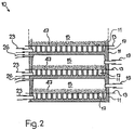
- a plate filter 10 is shown schematically in FIGS. 1 and 2.
- the plate filter 10 has a plate stack with a number of plates 11 that can be separated from one another. Between each two plates there is a filter belt section 13. Above the respective filter belt section 13 is the inlet chamber 15. The outlet chamber 17 is located below the filter belt 13. All inlet chambers 15 are connected via hoses 19 to a distributor 21 (FIG. 1). All outlet chambers 17 are connected to a collector 25 via hoses 23.
- the valves 58, 53, a distributor 24 and hoses 26 compressed air can be supplied to the inlet chambers 15, the liquid from the outlet chambers 17 (FIG. 2 ), the hoses 23, the collector 25 and the valves 36, 72 can flow into the tank 27.
- Line 29 leads from tank 27 for the liquid to be filtered to pump 31 and from there via valve 33 to distributor 21.
- Line 25 leads from collector 25 to valve 37.
- Valve 37 leads to tank 39 for the cleaned liquid.
- Tanks 39 and 27 are connected to one another by an overflow line 40.
- the reference number 41 indicates the line from the liquid user, e.g. from an aluminum rolling mill, referred to tank 27.
- the reference number 43 denotes the line from the tank 39 to the liquid user.
- the tank 45 contains the powdery or granular filter aid which is used to produce the precoat layers 47 (FIG. 2) on the filter belt 13.
- An agitator 49 is used to mix the powdery or granular filter aid with liquid.
- the suspension thus formed can then be pumped into the plate filter 10 via the lines 52, 29 to form the precoat layers 47 by means of the pump 51.
- FIGS. 1 and 2 essentially corresponds to the description of a known plate filter system, as was shown, for example, in US Pat. No. 3,608,734 or European Patent Application 0 132 829. For further details of such a system, reference can therefore be made to these publications.
- the fluid is supplied to the distributor 24 via the valve 53.
- a gas for example, can be used as the fluid which has the property of reducing the liquid content of the filter cake, for example by reducing the viscosity of the liquid. If a gas is thus heated by a fluid heater 55 to 60 to 300 degrees C and fed to the plate filter 10 via the valve 53, the heat causes the filter cake to heat up. The liquid still contained in the filter cake then loses viscosity and is therefore easily removed from the filter cake.
- heated compressed air can be used as the fluid.
- a line 57 with a valve 58 to the fluid heater 55 is therefore provided from the compressed air source 20.
- a gas e.g. Nitrogen or carbon dioxide.
- a line 60 with a valve 61 to the fluid heater 55 can therefore be provided from a source 59 for gas.
- nitrogen is often available as an inert gas.
- the liquid reduction essentially depends on four factors, namely the gas temperature, the flow rate, the time and the type of gas used.
- temperatures of 60 to 300 degrees C, preferably 150 to 250 degrees C, can be used depending on the requirements.
- a time of approximately 30 minutes down to approximately 5 minutes is to be expected as the treatment duration.
- the process can be optimized by selecting the appropriate parameters. It is also possible to work with a temperature curve. For example, the temperature can be lowered towards the end of the treatment period in order to cool the filter cake and the filter belt before removal from the plate filter.
- the filter cake cleaned with the described method can be disposed of more easily or, in many cases, can also be reused at least in part as a filter aid.
- a pump 65 can be provided.
- the circuit then leads from the outlet chambers 17 of the plate filter 10, the hoses 23, the valves 36, 71, the separator 69, e.g. Gas / liquid separator, line 70, pump 65, fluid heater 55, valve 53, manifold 24, and hoses 26 back to inlet chambers 15 of plate filter 10.
- a liquid e.g. a solvent
- a fluid tank 68 can be provided, from which a valve 66 is used to introduce the fluid into the process. It must of course be ensured that the fluid does not remain in the liquid to be cleaned.
- a suitable separator 69 e.g. Liquid / liquid separator provided. From the separator 69, the fluid reaches the fluid tank 68 via the pump 65. (In this case, the line 70 leads to the fluid tank 68 instead of a fluid heater 55). So there is also a fluid circulation here. The liquid separated from the filter cake is fed to the tank 27 via the line 74.
- the residual liquid contained therein after the filtering operation must be removed. This can be done by blowing out Compressed air or by suction. Compressed air from a compressed air source 20 can be used for blowing out, if one is provided.
- an injector 75 is shown, which can be connected to the outlet of the pump 31 via the valve 78. The suction connection of the injector 75 can be connected to the plate filter 10 via the valves 76, 32, 36 and the distributor 21 or collector 25, from which the residual liquid can then be conveyed into the tank 27 by the action of the injector. The closing of the valves 71, 72 prevents the intake of air.
- the floating, i.e. the formation of the precoat from filter aids begins after new filter belt sections 13 have been drawn into the plate filter 10.
- the valves 33, 36, 72 are open.
- the valves 37, 30 and 53 are closed.
- the pumps 31 and 51 are running.
- the pump 51 pumps the suspension contained in the tank 45 via the line 29, the open valve 33 and the distributor 21 into the chambers 15 of the plate filter 10, where the suspension is distributed over the filter belt sections 13.
- the liquid flows through the respective filter band section 13 into the outlet chamber 17 and from there via the hose 23, the collector 25, and the valves 36, 72 into the tank 27.
- the air initially contained in the plate filter 10 flows out of the inlet chambers 15 the hoses 26, the collector 24, the line 28 and the valve 30 into the tank 27, whereupon the valve 30 is closed.
- the tank 27 is vented via the overflow line 40, the tank 39 and the line 63.
- Valves 30, 33 and 37 are open during the filtering operation. Contaminated liquid from the tank 27 is pumped through the plate filter 10 by means of the pump 31. The cleaned one Liquid from the plate filter 10 flows via the line 35 and the opened valve 37 into the tank 39. In the filtering operation, too, filter aid is conveyed by the pump 51, for example intermittently, in metered amounts.
- the filtering operation is interrupted to replace precoat layers and filter belt sections.
- the liquid contained in the plate filter 10 must be drained. This is done, for example, by blowing compressed air out of the compressed air source 20.
- compressed air having normal temperature flows with a pressure of preferably 4 bar or higher through the distributor 24 and the hoses 26 into the inlet chamber 15 (FIG. 2) and presses the liquid present there through the precoat layers 47 and the filter belt sections 13 into the outlet chambers 17.
- Another way to draw off the residual liquid is to use a vacuum. If no compressed air source 20 is available, an injector 75 can therefore be provided.
- the pump 31 when running, the valve 33 is closed and the valve 78 is open, the liquid circuit from the tank 27 via the pump 31 and the injector 75 to the tank 27 generates a negative pressure which, when the valves 71, 72 are closed, via the open valves 76 , 36 and 32 sucks the residual liquid from the plate filter 10.
- the residual liquid reaches the tank 27 via the injector 75.
- the method according to the invention for reducing the liquid content of the filter cake obtained in a plate filter now provides that a fluid flows through the filter cake before it is removed within the plate filter 10, which fluid improves the removal of liquid from the filter cake.
- Hot compressed air for example, can be used as such a fluid.
- compressed air from the compressed air source 20 is fed into the plate filter 10 via the valve 58, the switched on fluid heater 55, the valve 53, the distributor 24 and the hoses 26.
- the heat causes the filter cake to heat up, which causes the remaining liquid to have a lower viscosity and is therefore expelled from the filter cake much better. Together with the air, the expelled liquid flows from the outlet chambers 17 (FIG.
- the ventilation of the tank 27 takes place via the overflow line 40, the tank 39 and the line 63.
- the possible working temperature of the fluid is limited in particular by three factors, namely the type of fluid used, the liquid which is to be separated from the filter cake and the material of the hoses 23, 26. In any case, it must be avoided that there is a risk of fire or explosion or that the hoses are damaged by the effects of temperature.
- inert gas from the source 59 can be supplied to the plate filter 10 via the valve 61, the fluid heater 55 and the valve 53. It is also possible to empty the plate filter with compressed air before introducing this fluid.
- valve 64 can be closed and the pump 65 can be switched on some time after the valve 61 has opened, that is to say when there is no more air in the system.
- a suitable separator 69 can be used for this purpose. If necessary, after the use of a liquid as a fluid to reduce the liquid content of the filter cake, a rinsing with a gaseous fluid can be carried out in order to remove residues of the liquid fluid.
- the filter cake (47) is still inside the plate filter (10) from a fluid, e.g. a gas with a temperature of 60 to 300 degrees C, which promotes the removal of liquid from the filter cake.
- a fluid e.g. a gas with a temperature of 60 to 300 degrees C
- the liquid content of around 30 to 50 percent contained in the filter cake can be almost completely removed and reused.
- the treated filter cake is largely free of liquid when removed from the plate filter and can therefore be disposed of more easily and cheaply than before. Reuse as a filter aid is also possible because the particles practically no longer stick together, but are almost back to their original condition.
- the particles are in turn able to form a highly porous filter cake. At least a part of the cleaned material can therefore be reused, so that the amount of waste material to be landfilled is greatly reduced.
Landscapes
- Chemical & Material Sciences (AREA)
- Chemical Kinetics & Catalysis (AREA)
- Filtration Of Liquid (AREA)
- Fats And Perfumes (AREA)
Abstract
Description
Die Erfindung betrifft ein Verfahren zur Reduktion des Flüssigkeitsgehalts des bei einem Plattenfilter anfallenden Filterkuchens.The invention relates to a method for reducing the liquid content of the filter cake obtained in a plate filter.
Die US Patente 3 608 734, 4 869 834 und die europäischen Patentanmeldungen 0 032 829, 0 304 597 beschreiben einen Plattenfilter mit einem Plattenstapel, der eine Anzahl von voneinander separierbaren Platten aufweist. Zwischen je zwei Platten befindet sich ein Filterband, durch welches eine Einlasskammer auf der Unterseite der oberen Platte von einer Auslasskammer auf der Oberseite der darunter angeordneten Platte abgegrenzt wird. Die zu reinigende Flüssigkeit, z.B. Walzöl eines Aluminiumwalzwerkes mit einer Temperatur von 40 bis 70 Grad C, wird der Einlasskammer zugeführt, von wo dann die Flüssigkeit durch einen Abschnitt des Filterbandes hindurch in die Auslasskammer fliesst. Sämtliche Einlasskammern sind mit einem gemeinsamen Verteiler, und sämtliche Auslasskammern sind mit einem gemeinsamen Kollektor verbunden. Von diesem Kollektor fliesst die gereinigte Flüssigkeit zu einem Tank und steht dann zu neuem Einsatz bereit. Für jedes Filterband ist eine Filterband-Transportvorrichtung vorgesehen, um periodisch einen gebrauchten Filterbandabschnitt durch einen frischen Filterbandabschnitt zu ersetzen. Um dies zu ermöglichen, werden die Platten des Plattenstapels voneinander separiert. Dazu ist eine Vorrichtung vorgesehen, welche zusätzlich auch die Aufgabe besitzt, die Platten nach dem Transport des Filterbandes zusammenzupressen, damit sie einen neuen Filterbandabschnitt zwischen den Rändern der Einlasskammer und der Auslasskammer festklemmen. Durch das Festklemmen des Filterbandes wird eine Dichtung bewirkt. Eine umlaufende Nut in der Nähe des Plattenrandes fängt etwaige Leckflüssigkeit auf, die dann durch ein Vakuum abgesogen wird.US Pat. Nos. 3,608,734, 4,869,834 and European patent applications 0 032 829, 0 304 597 describe a plate filter with a plate stack which has a number of plates which can be separated from one another. There is a filter belt between each two plates, through which an inlet chamber on the underside of the upper plate is delimited from an outlet chamber on the upper side of the plate arranged below. The liquid to be cleaned, e.g. Rolling oil of an aluminum rolling mill with a temperature of 40 to 70 degrees C is fed to the inlet chamber, from where the liquid then flows through a section of the filter belt into the outlet chamber. All inlet chambers are connected to a common distributor and all outlet chambers are connected to a common collector. The cleaned liquid flows from this collector to a tank and is then ready for new use. A filter belt transport device is provided for each filter belt in order to periodically replace a used filter belt section with a fresh filter belt section. To make this possible, the plates of the plate stack are separated from one another. For this purpose, a device is provided, which also has the task of pressing the plates together after the transport of the filter belt so that they clamp a new filter belt section between the edges of the inlet chamber and the outlet chamber. Clamping the filter band creates a seal. A circumferential groove near the edge of the plate catches any leakage fluid, which is then sucked off by a vacuum.
Wenn die verschmutzte Flüssigkeit einer Absorption oder Adsorption, z.B. mittels Kieselgur oder Bleicherde, unterzogen werden soll, so wird solches Filterhilfsmittel in körniger oder pulverförmiger Form der Flüssigkeit zugemischt und als Anschwemmschicht auf die im Plattenfilter befindlichen Filterbandabschnitte aufgetragen. Die Korngrösse des Absorptions- oder Adsorptionsmaterials und die Porengrösse des Filterbandes werden derart gewählt, dass das körnige oder pulverförmige Filterhilfsmittel auf den Filterbandabschnitten verbleibt. Die zu filtrierende Flüssigkeit wird im Betrieb des Plattenfilters durch die Anschwemmschichten und die Filterbandabschnitte gepresst und erfährt dabei die durch das Filterhilfsmittel und die Filterbandabschnitte beabsichtigte Reinigung.If the contaminated liquid is to be subjected to absorption or adsorption, for example by means of diatomaceous earth or bleaching earth, such a filter aid becomes granular or powdered form of the liquid and applied as a precoat to the filter belt sections located in the plate filter. The grain size of the absorption or adsorption material and the pore size of the filter belt are selected such that the granular or powdery filter aid remains on the filter belt sections. During the operation of the plate filter, the liquid to be filtered is pressed through the precoat layers and the filter belt sections and experiences the cleaning intended by the filter aid and the filter belt sections.
Wenn das Filterhilfsmittel erschöpft ist und das Filterband durch die Aufnahme von Schmutzstoffen einen übermässig hohen Druck für das Durchpumpen der Flüssigkeit benötigt, so müssen die Anschwemmschicht und das Filterband ersetzt werden. Um dies zu ermöglichen, müssen die Einlasskammern und die Auslasskammern entleert werden. Dies geschieht in der Regel durch Druckluft, welche in die Einlasskammern eingeführt wird. Diese etwa Umgebungstemperatur aufweisende Druckluft presst die sich in der jeweiligen Einlasskammer befindliche Flüssigkeit durch die Anschwemmschicht und den Filterbandabschnitt hindurch in die Auslasskammer. Von dort kann die von der Druckluft getriebene Restflüssigkeit zum gemeinsamen Auslass und weiter zum Tank für gereinigte Flüssigkeit fliessen. Statt mit Druckluft kann der Plattenfilter aber auch durch Anlegen eines Unterdrucks an die Auslasskammern entleert werden. Bekannt ist zu diesem Zweck die Verwendung eines Injektors.If the filter aid is exhausted and the filter belt requires an excessively high pressure to pump the liquid through the absorption of contaminants, the precoat and the filter belt must be replaced. To make this possible, the inlet chambers and the outlet chambers must be emptied. This is usually done using compressed air that is introduced into the inlet chambers. This compressed air, which has approximately ambient temperature, presses the liquid located in the respective inlet chamber through the precoat and the filter belt section into the outlet chamber. From there, the residual liquid driven by the compressed air can flow to the common outlet and on to the tank for cleaned liquid. Instead of using compressed air, the plate filter can also be emptied by applying a vacuum to the outlet chambers. The use of an injector is known for this purpose.
Nach der Entleerung der Restflüssigkeit aus dem Plattenfilter werden die Filterplatten zuerst voneinander separiert, worauf dann die Filterband-Transportvorrichtung betätigt wird. Dies hat zur Folge, dass die Filterbandabschnitte mit den schmutzigen Anschwemmschichten aus dem Plattenfilter hinaustransportiert und frische Filterbandabschnitte eingezogen werden, worauf dann die Platten wieder zusammengepresst werden, damit sie die neuen Filterbandabschnitte festklemmen.After the residual liquid has been emptied from the plate filter, the filter plates are first separated from one another, whereupon the filter belt transport device is actuated. As a result, the filter belt sections with the dirty precoat layers are transported out of the plate filter and fresh filter belt sections are drawn in, whereupon the plates are pressed together again so that they clamp the new filter belt sections.
Die schmutzige Anschwemmschicht, der sogenannte Filterkuchen, enthält nicht nur Schmutzstoffe, sondern besitzt in der Regel auch einen relativ hohen Flüssigkeitsgehalt. Bei der Reinigung von Walzöl für Aluminiumwalzwerke beträgt der Flüssigkeitsgehalt des mit Druckluft teilweise entölten Filterkuchens etwa 30 bis 50 Gewichtsprozent. Dieser Flüssigkeitsgehalt wurde bisher in Kauf genommen. Er stellt aber in zweierleier Hinsicht ein Problem dar. Einerseits entsteht dadurch ein Verlust von Flüssigkeit; andererseits schafft der Flüssigkeitsgehalt des Filterkuchens erhebliche Entsorgungsprobleme. So darf z.B. stark mineralölhaltiger Filterkuchen nicht in einer Deponie gelagert werden, sondern muss z.B. in einem Verbrennungsofen entsorgt werden, was mit erheblichen Kosten verbunden ist.The dirty precoat, the so-called filter cake, not only contains contaminants, but usually also has a relatively high liquid content. When cleaning rolling oil for aluminum rolling mills, the liquid content of the filter cake, partially de-oiled with compressed air, is about 30 to 50 percent by weight. This liquid content has so far been accepted. However, it is a problem in two respects. On the one hand, this causes a loss of fluid; on the other hand, the liquid content of the filter cake creates considerable disposal problems. For example, filter cake with a high mineral oil content should not be stored in a landfill, but must e.g. be disposed of in an incinerator, which is associated with considerable costs.
Es ist daher Aufgabe der vorliegenden Erfindung, ein Verfahren zur Reduktion des Flüssigkeitsgehalts des bei einem Plattenfilter anfallenden Filterkuchens zu schaffen.It is therefore an object of the present invention to provide a method for reducing the liquid content of the filter cake resulting from a plate filter.
Erfindungsgemäss wird diese Aufgabe dadurch gelöst, dass der Filterkuchen noch vor dessen Entnahme innerhalb des Plattenfilters mit einem den Flüssigkeitsentzug aus dem Filterkuchen verbesserndem Fluidum behandelt wird. Die Wahl des Fluidums hängt dabei von verschiedenen Faktoren ab, z.B. von der Art der Flüssigkeit, die mit dem Plattenfilter gereinigt wurde, von der Art des Filterhilfsmittels, von der Art des Filterbandes, usw. Verschiedene Fluida können den Flüssigkeitsentzug auf unterschiedliche Weise fördern, z.B. durch Aenderung der Viskosität, durch Veränderung der Adsorptions- oder Absorptionseigenschaften des Filterhilfsmittels, durch die Lösungswirkung, usw. Die physikalischen und/oder chemischen Vorgänge sind aber nicht in allen Fällen klar. Durch das Fluidum wird die im Filterkuchen enthaltene Flüssigkeit noch vor der Entfernung des Filterkuchens aus dem Plattenfilter reduziert. Die so wiedergewonnene Flüssigkeit kann in der Regel wieder verwendet werden. Je nach der Art der Flüssigkeit, die im Plattenfilter gereinigt wurde und der Art des Fluidums, welches zur Reduktion des Flüssigkeitsgehaltes des Filterkuchens verwendet wurde, hat der Filterkuchen, wenn er dem Plattenfilter entnommen wird, einen stark reduzierten und in gewissen Fällen sogar praktisch vollständig reduzierten Flüssigkeitsgehalt. Dadurch wird die Entsorgung des Filterkuchens entsprechend erleichtert.According to the invention, this object is achieved in that the filter cake is treated with a fluid which improves the removal of liquid from the filter cake before it is removed within the plate filter. The choice of fluid depends on various factors, e.g. the type of liquid that has been cleaned with the plate filter, the type of filter aid, the type of filter belt, etc. Different fluids can promote fluid withdrawal in different ways, e.g. by changing the viscosity, by changing the adsorption or absorption properties of the filter aid, by the dissolving action, etc. However, the physical and / or chemical processes are not clear in all cases. The fluid contained in the filter cake reduces the liquid before the filter cake is removed from the plate filter. The liquid thus recovered can usually be reused. Depending on the type of liquid that was cleaned in the plate filter and the type of fluid used to reduce the liquid content of the Filter cake was used, the filter cake, when removed from the plate filter, has a greatly reduced and in some cases even practically completely reduced liquid content. This makes the disposal of the filter cake easier.
Da erfindungsgemäss das Verfahren zur Reduktion des Flüssigkeitsgehalts im Plattenfilter selbst stattfindet, sind nur wenig zusätzliche Apparaturen notwendig. Dies erlaubt es, die Investitionskosten gering zu halten.Since, according to the invention, the process for reducing the liquid content takes place in the plate filter itself, only a few additional devices are necessary. This allows the investment costs to be kept low.
Vorzugsweise ist bei der Reduktion des Flüssigkeitsgehalts des Filterkuchens die Strömungsrichtung des Fluidums im Plattenfilter die gleiche wie bei der Filtrierung. Dies ermöglicht die Realisierung des Verfahrens ohne grossen apparativen Aufwand, weil dabei zur Flüssigkeitsreduktion im wesentlichen die gleichen Apparaturen wie für die Filtrierung verwendet werden können.In the reduction of the liquid content of the filter cake, the direction of flow of the fluid in the plate filter is preferably the same as in the filtration. This enables the implementation of the method without great expenditure on equipment, because essentially the same equipment as for the filtration can be used to reduce the liquid.
In gewissen Fällen ist es vorteilhaft, zur Erhöhung der Extraktionswirkung das Fluidum vor der Einleitung in den Plattenfilter auf eine erhöhte Temperatur, z.B. 60 bis 300 Grad, vorzugsweise 150 bis 250 Grad C, zu bringen. Dadurch wird der Filterkuchen aufgeheizt, so dass die darin enthaltene Flüssigkeit eine geringere Viskosität erhält und daher wesentlich leichter aus dem Filterkuchen ausfliesst. Mit Vorteil weist das verwendete Fluidum eine gute Absorptionskapazität für die zu entfernende Flüssigkeit auf. Das Fluidum ist vorteilhaft gasförmig. Dies ermöglicht es, die herausgelöste Flüssigkeit und das Fluidum ohne grossen Aufwand zu trennen. Je nach der Art der im Filterkuchen enthaltenen Flüssigkeit, kann ein gasförmiges oder ein flüssiges Fluidum verwendet werden. In gewissen Fällen kann als Fluidum erwärmte Druckluft zur Anwendung gelangen. Da Druckluft in den meisten industriellen Betrieben zur Verfügung steht, sind nur geringe Investitionen zur Durchführung des Verfahrens notwendig. Mit grossem Vorteil wird aber als Fluidum ein Gas wie Stickstoff oder Kohlendioxid, verwendet. Dadurch kann eine Explosionsgefahr vermieden werden, insbesonders, wenn mit erhöhter Temperatur gearbeitet wird. Die Verwendung von Stickstoff, Kohlendioxid oder anderem inertem Gas ist insbesondere dann von Vorteil, wenn die Flüssigkeit, z.B. Walzöl, im Filterkuchen einen niedrigen Flammpunkt aufweist. Versuche haben gezeigt, dass Stickstoff sich sehr gut zum Herauslösen von Walzöl eignet. Es wird angenommen, dass Stickstoff eine gute Absobtionsfähigkeit für Walzöl aufweist. Es ist aber durchaus denkbar, dass dies auch für andere Gase zutrifft. Die Wahl des verwendeten Gases hängt dabei nicht nur von diesen Eigenschaften, sondern auch von der Leichtigkeit von dessen Beschaffung und dessen Kosten am Standort des Plattenfilters ab, wo es zum Einsatz gelangt.In certain cases it is advantageous to bring the fluid to an elevated temperature, for example 60 to 300 degrees, preferably 150 to 250 degrees C, before being introduced into the plate filter. This heats up the filter cake so that the liquid contained therein has a lower viscosity and therefore flows out of the filter cake much more easily. The fluid used advantageously has a good absorption capacity for the liquid to be removed. The fluid is advantageously gaseous. This makes it possible to separate the extracted liquid and the fluid with little effort. Depending on the type of liquid contained in the filter cake, a gaseous or a liquid fluid can be used. In certain cases, heated compressed air can be used as the fluid. Since compressed air is available in most industrial companies, only a small investment is required to carry out the process. With great advantage, however, a gas such as nitrogen or carbon dioxide is used as the fluid. This avoids the risk of explosion, especially when working at elevated temperatures becomes. The use of nitrogen, carbon dioxide or other inert gas is particularly advantageous if the liquid, eg rolling oil, has a low flash point in the filter cake. Experiments have shown that nitrogen is very suitable for removing rolling oil. Nitrogen is believed to have a good absorbing ability for rolling oil. However, it is quite conceivable that this also applies to other gases. The choice of the gas used depends not only on these properties, but also on the ease of its procurement and its cost at the location of the plate filter where it is used.
In gewissen Fällen kann zur Reduktion des Flüssigkeitsgehalts des Filterkuchens ein Fluidum in Form eines Lösungsmittels verwendet werden. Denkbar ist auch die Verwendung von Dampf als Fluidum.In certain cases, a fluid in the form of a solvent can be used to reduce the liquid content of the filter cake. The use of steam as a fluid is also conceivable.
Statt das Fluidum durch Anwendung von Druck durch den Plattenfilter zu fördern, kann es auch durch Anlegen eines Unterdrucks an den Ausgang des Plattenfilters gefördert werden. Die Erzeugung des Unterdrucks kann z.B. durch einen Injektor erfolgen. Da Injektoren relativ einfache Vorrichtungen darstellen, können die Investitionskosten niedrig gehalten werden. Dies gilt vor allem dann, wenn keine Druckluft zur Verfügung steht und die Auslagen für eine Kompressoranlage vermieden werden können.Instead of pumping the fluid through the plate filter by applying pressure, it can also be pumped by applying a vacuum to the outlet of the plate filter. The generation of the negative pressure can e.g. done by an injector. Since injectors are relatively simple devices, the investment costs can be kept low. This is especially true when compressed air is not available and the expenses for a compressor system can be avoided.
Wird das Fluidum, z.B. Stickstoff, als Verbrauchsmaterial betrachtet und nicht durch Kreislauf einer Wiederverwertung zugeführt, so können die Investionskosten für den apparativen Aufwand, der notwendig ist, um das Verfahren durchzuführen, sehr niedrig gehalten werden.If the fluid, e.g. Nitrogen, viewed as a consumable and not recycled by recycling, can keep the investment costs for the equipment required to carry out the process very low.
Es ist aber auch möglich, das Fluidum im Kreislauf zu führen. Dies hat den Vorteil, dass die Kosten für ein Fluidum, wie Stickstoff oder Kohlendioxid, klein gehalten werden können.However, it is also possible to circulate the fluid. This has the advantage that the costs for a fluid such as nitrogen or carbon dioxide can be kept low.
Die Erfindung betrifft auch eine Vorrichtung zur Durchführung des Verfahrens. Diese Vorrichtung ist dadurch gekennzeichnet, dass über ein Ventil die Einlässe zu den Einlasskammern an eine Fluidumquelle anschliessbar sind. Dies ermöglicht die Durchführung des Verfahrens mit geringem apparativem Aufwand.The invention also relates to an apparatus for performing the method. This device is characterized in that that the inlets to the inlet chambers can be connected to a fluid source via a valve. This enables the method to be carried out with little expenditure on equipment.
Es ist möglich, eine Kreislaufleitung über Ventile von den Auslasskammern zu den Einlasskammern herzustellen. Durch die Kreislaufführung kann der Verbrauch an Fluidum klein gehalten werden.It is possible to create a circuit line via valves from the outlet chambers to the inlet chambers. The circulation can keep the consumption of fluid low.
Wenn z.B. ein inertes Gas als Fluidum verwendet wird, kann ein Vorratsbehälter, z.B. ein Druckbehälter, vorgesehen sein, um nach Bedarf Fluidum in das Verfahren einzuführen.If e.g. an inert gas is used as the fluid, a reservoir, e.g. a pressure vessel may be provided to introduce fluid into the process as needed.
Zur Aufrechterhaltung des Kreislaufs kann eine Fluidumpumpe vorgesehen sein.A fluid pump can be provided to maintain the circulation.
In gewissen Fällen ist es zweckmässig, einen Flüssigkeits/Gas-Separator vorzusehen.In certain cases it is advisable to provide a liquid / gas separator.
Ein Ausführungsbeispiel der Erfindung wird nun unter Bezugnahme auf die Zeichnung beschrieben. Es zeigt:
- Figur 1
- eine schematische Darstellung der Vorrichtung zur Durchführung des Verfahrens und
- Figur 2
- eine schematische Darstellung eines Plattenfilters.
- Figure 1
- a schematic representation of the device for performing the method and
- Figure 2
- a schematic representation of a plate filter.
In den Figuren 1 und 2 ist schematisch ein Plattenfilter 10 dargestellt. Wie Figur 2 zeigt, besitzt der Plattenfilter 10 einen Plattenstapel mit einer Anzahl von voneinander separierbaren Platten 11. Zwischen je zwei Platten befindet sich ein Filterbandabschnitt 13. Ueber dem jeweiligen Filterbandabschnitt 13 ist die Einlasskammer 15. Die Auslasskammer 17 befindet sich unterhalb des Filterbandes 13. Sämtliche Einlasskammern 15 sind über Schläuche 19 an einem Verteiler 21 (Fig. 1) angeschlossen. Sämtliche Auslasskammern 17 sind über Schläuche 23 an einen Kollektor 25 angeschlossen. Wie später noch näher beschrieben wird, kann zur Entleerung des Plattenfilters 10 von einer Druckluftquelle 20 über die Leitung 57, die Ventile 58, 53, einen Verteiler 24 und Schläuche 26 den Einlasskammern 15 Druckluft zugeführt werden, wobei die Flüssigkeit aus den Auslasskammern 17 (Fig. 2), die Schläuche 23, den Kollektor 25 und die Ventile 36, 72 in den Tank 27 fliessen kann.A
Vom Tank 27 für die zu filtrierende Flüssigkeit führt die Leitung 29 zur Pumpe 31 und von dort über das Ventil 33 zum Verteiler 21. Vom Kollektor 25 führt die Leitung 35 zum Ventil 37. Das Ventil 37 führt zum Tank 39 für die gereinigte Flüssigkeit. Tanks 39 und 27 sind mit einer Ueberlaufleitung 40 miteinander verbunden. Mit der Bezugsziffer 41 ist die Leitung vom Flüssigkeitsanwender, z.B. von einem Aluminiumwalzwerk, zum Tank 27 bezeichnet. Die Bezugsziffer 43 bezeichnet die Leitung vom Tank 39 zum Flüssigkeitsanwender.
Der Tank 45 enthält das pulverförmige oder körnige Filterhilfsmittel, welches zur Herstellung der Anschwemmschichten 47 (Fig. 2) auf dem Filterband 13 verwendet wird. Ein Rührwerk 49 dient der Durchmischung des pulverförmigen oder körnigen Filterhilfsmittels mit Flüssigkeit. Die so gebildete Suspension kann dann zur Bildung der Anschwemmschichten 47 mittels der Pumpe 51 über die Leitungen 52, 29 in den Plattenfilter 10 gepumpt werden.The
Die bisherige Beschreibung der Figuren 1 und 2 entspricht im wesentlichen der Beschreibung einer bekannten Plattenfilteranlage, wie sie beispielsweise im US-Patent 3 608 734 oder der europäischen Patentanmeldung 0 132 829 dargestellt wurde. Für weitere Einzelheiten einer solchen Anlage kann daher auf diese Druckschriften verwiesen werden.The previous description of FIGS. 1 and 2 essentially corresponds to the description of a known plate filter system, as was shown, for example, in US Pat. No. 3,608,734 or European Patent Application 0 132 829. For further details of such a system, reference can therefore be made to these publications.
Zur Durchführung des Verfahrens zur Reduktion des Flüssigkeitsgehalts des Filterkuchens wird das Fluidum über das Ventil 53 dem Verteiler 24 zugeführt. Wie bereits einleitend beschrieben wurde, kann als Fluidum z.B. ein Gas verwendet werden, welches die Eigenschaft besitzt, den Flüssigkeitsgehalt des Filterkuchens zu verringern, beispielsweise durch Verminderung der Viskosität der Flüssigkeit. Wird somit ein Gas durch einen Fluidumerhitzer 55 auf 60 bis 300 Grad C aufgeheizt und über das Ventil 53 dem Plattenfilter 10 zugeführt, so bewirkt die Wärme ein Aufheizen der Filterkuchen. Die noch im Filterkuchen enthaltene Flüssigkeit verliert dann an Viskosität und wird somit leicht aus dem Filterkuchen ausgeschieden. Als Fluidum kann beispielsweise erhitzte Druckluft zur Anwendung gelangen. Es ist daher von der Druckluftquelle 20 eine Leitung 57 mit einem Ventil 58 zum Fluidumerhitzer 55 vorgesehen.To carry out the method for reducing the liquid content of the filter cake, the fluid is supplied to the
Werden mit dem Plattenfilter Flüssigkeiten mit niedrigem Flammpunkt behandelt, so wird aber als Fluidum zweckmässigerweise ein Gas, z.B. Stickstoff oder Kohlendioxid, vorgesehen. Es kann daher von einer Quelle 59 für Gas eine Leitung 60 mit einem Ventil 61 zum Fluidumerhitzer 55 vorgesehen sein. In Aluminiumwalzen, wo Plattenfilter Anwendung finden, steht oft Stickstoff als inertes Gas zur Verfügung.If liquids with a low flash point are treated with the plate filter, a gas, e.g. Nitrogen or carbon dioxide. A
Bei einem Versuch wurde während 30 Minuten Stickstoff mit einer Temperatur von 230 Grad C dem Plattenfilter eines Aluminiumwalzwerkes zugeführt. Nach der Entnahme aus dem Plattenfilter enthielt der Filterkuchen noch 0,1 Prozent Walzöl. Dieser Wert liegt wesentlich unter den in den meisten Ländern gültigen Grenzwerten. In der Regel wird ein Oelgehalt von 0,5 Prozent noch als zulässig betrachtet.In one experiment, nitrogen was fed to the plate filter of an aluminum rolling mill at a temperature of 230 degrees C for 30 minutes. After removal from the plate filter, the filter cake still contained 0.1 percent rolling oil. This value is significantly below the limit values applicable in most countries. As a rule, an oil content of 0.5 percent is still considered permissible.
Die Flüssigkeitsreduktion hängt im wesentlichen von vier Faktoren ab, nämlich von der Gastemperatur, der Durchflussrate, der Zeit und der Art des verwendeten Gases.The liquid reduction essentially depends on four factors, namely the gas temperature, the flow rate, the time and the type of gas used.
In der Praxis kann je nach den Erfordernissen mit Temperaturen von 60 bis 300 Grad C, vorzugsweise 150 bis 250 Grad C, gearbeitet werden. Dabei ist mit einer Zeit von etwa 30 Minuten bis hinunter auf etwa 5 Minuten als Behandlungsdauer zu rechnen.In practice, temperatures of 60 to 300 degrees C, preferably 150 to 250 degrees C, can be used depending on the requirements. A time of approximately 30 minutes down to approximately 5 minutes is to be expected as the treatment duration.
Das Verfahren kann durch entsprechende Wahl der Parameter optimiert werden. Auch ist es möglich, mit einer Temperaturkurve zu arbeiten. So kann beispielsweise die Temperatur gegen den Schluss der Behandlungsdauer abgesenkt werden, um den Filterkuchen und das Filterband vor der Entnahme aus dem Plattenfilter abzukühlen.The process can be optimized by selecting the appropriate parameters. It is also possible to work with a temperature curve. For example, the temperature can be lowered towards the end of the treatment period in order to cool the filter cake and the filter belt before removal from the plate filter.
Der mit dem beschriebenen Verfahren gereinigte Filterkuchen kann leichter entsorgt oder in vielen Fällen auch mindestens zum Teil als Filterhilfsmittel wiederverwendet werden.The filter cake cleaned with the described method can be disposed of more easily or, in many cases, can also be reused at least in part as a filter aid.
Um die Kosten für Gas gering zu halten, wäre es möglich, dieses im Kreislauf zu führen. Zu diesem Zweck kann z.B. eine Pumpe 65 vorgesehen werden. Der Kreislauf führt dann von den Auslasskammern 17 des Plattenfilters 10, die Schläuche 23, die Ventile 36, 71, den Separator 69, z.B. Gas/Flüssigkeit-Separator, die Leitung 70, die Pumpe 65, den Fluidumerhitzer 55, das Ventil 53, den Verteiler 24 und die Schläuche 26 zurück zu den Einlasskammern 15 des Plattenfilters 10.In order to keep the cost of gas low, it would be possible to recycle it. For this purpose e.g. a
Es wäre auch möglich, eine Flüssigkeit, z.B. ein Lösungsmittel, zur Reduktion des Flüssigkeitsgehalts des Filterkuchens zu verwenden. Zu diesem Zweck kann ein Fluidumtank 68 vorgesehen werden, von welchem ein Ventil 66 zum Einführen des Fluidums in das Verfahren dient. Dabei muss natürlich dafür gesorgt werden, dass das Fluidum nicht in der zu reinigenden Flüssigkeit verbleibt. Zu diesem Zweck ist ein geeigneter Separator 69, z.B. Flüssigkeit/Flüssigkeit-Separator, vorgesehen. Vom Separator 69 gelangt das Fluidum über die Pumpe 65 zurück zum Fluidumtank 68. (Statt zu einem Fluidumerhitzer 55 führt die Leitung 70 in diesem Fall zum Fluidumtank 68). Es besteht also auch hier ein Fluidumkreislauf. Die aus dem Filterkuchen abgeschiedene Flüssigkeit wird über die Leitung 74 dem Tank 27 zugeführt.It would also be possible to add a liquid, e.g. a solvent to use to reduce the liquid content of the filter cake. For this purpose, a
Bevor eine Reduktion des Flüssigkeitsgehalts des Filterkuchens innerhalb des Plattenfilters vorgenommen werden kann, muss die in diesem nach der Filtrieroperation enthaltene Restflüssigkeit entfernt werden. Dies kann durch Ausblasen mit Druckluft oder durch Absaugen erfolgen. Zum Ausblasen kann Druckluft von einer Druckluftquelle 20 dienen, falls eine solche vorgesehen ist. Zum Absaugen wird ein Injektor 75 gezeigt, der über das Ventil 78 an den Ausgang der Pumpe 31 angeschlossen werden kann. Der Sauganschluss des Injektors 75 ist über die Ventile 76, 32, 36 und den Verteiler 21, bzw. Kollektor 25, an den Plattenfilter 10 anschliessbar, aus welchem dann durch die Injektorwirkung die Restflüssigkeit in den Tank 27 gefördert werden kann. Das Schliessen der Ventile 71, 72 verhindert das Ansaugen von Luft.Before a reduction in the liquid content of the filter cake within the plate filter can be carried out, the residual liquid contained therein after the filtering operation must be removed. This can be done by blowing out Compressed air or by suction. Compressed air from a
Bevor nun die Wirkungsweise der Anlage bei der Reduktion des Flüssigkeitsgehalts der Filterkuchen beschrieben wird, soll zuerst das Voranschwemmen, die Filtrieroperation und das Entleeren der Restflüssigkeit aus dem Plattenfilter beschrieben werden.Before the operation of the system in reducing the liquid content of the filter cake is described, the precoat, the filtering operation and the emptying of the residual liquid from the plate filter should first be described.
Das Voranschwemmen, d.h. der Beginn der Bildung der Anschwemmschicht aus Filterhilfsmittel, erfolgt nach dem Einziehen neuer Filterbandabschnitte 13 in den Plattenfilter 10. Die Ventile 33, 36, 72 sind offen. Die Ventile 37, 30 und 53 sind geschlossen. Die Pumpen 31 und 51 laufen. Die Pumpe 51 pumpt dabei die im Tank 45 enthaltene Suspension über die Leitung 29, das offene Ventil 33 und den Verteiler 21 in die Kammern 15 des Plattenfilters 10, wo sich die Suspension über die Filterbandabschnitte 13 verteilt. Die Flüssigkeit fliesst durch den jeweiligen Filterbandabschnitt 13 hindurch in die Auslasskammer 17 und von dort über den Schlauch 23, den Kollektor 25, und die Ventile 36, 72 in den Tank 27. Die zu Beginn im Plattenfilter 10 enthaltene Luft strömt aus den Einlasskammern 15 durch die Schläuche 26, den Kollektor 24, die Leitung 28 und das Ventil 30 in den Tank 27, worauf das Ventil 30 geschlossen wird. Die Entlüftung des Tanks 27 erfolgt über die Ueberlaufleitung 40, den Tank 39 und die Leitung 63.The floating, i.e. the formation of the precoat from filter aids begins after new
Bei der Filtrieroperation sind die Ventile 30, 33 und 37 offen. Verunreinigte Flüssigkeit aus dem Tank 27 wird mittels der Pumpe 31 durch den Plattenfilter 10 gepumpt. Die gereinigte Flüssigkeit aus dem Plattenfilter 10 fliesst über die Leitung 35 und das geöffnete Ventil 37 in den Tank 39. Auch bei der Filtrieroperation wird durch die Pumpe 51, z.B. intermittierend, in dosierten Mengen Filterhilfsmittel gefördert.
Wenn das Absorptions- oder Adsorptionsmaterial erschöpft ist und/oder die in Betrieb stehenden Filterbandabschnitte wegen der erfolgten Aufnahme von Schmutzstoffen einen übermässig hohen Druck zum Durchpumpen der Flüssigkeit benötigen, wird die Filtrieroperation unterbrochen, um Anschwemmschichten und Filterbandabschnitte zu ersetzen. Zu diesem Zweck muss die im Plattenfilter 10 enthaltene Flüssigkeit abgelassen werden. Dies geschieht beispielsweise durch Ausblasen mit Druckluft aus der Druckluftquelle 20. Bei geöffneten Ventilen 58, 53 und nicht in Betrieb stehendem Fluiderhitzer 55 strömt Normaltemperatur aufweisende Druckluft mit einem Druck von vorzugsweise 4 bar oder höher durch den Verteiler 24 und die Schläuche 26 in die Einlasskammer 15 (Fig. 2) und presst die dort vorhandene Flüssigkeit durch die Anschwemmschichten 47 und die Filterbandabschnitte 13 hindurch in die Auslasskammern 17. Von dort fliesst die Flüssigkeit über die Schläuche 23 in den Kollektor 25 und von dort über die offenen Ventile 36, 72 in den Tank 27. Das Ventil 37 ist geschlossen, damit keine Flüssigkeit in den Tank 39 gelangt. Nach dem Abfliessen der in den Einlasskammern 15 des Plattenfilters enthaltene Flüssigkeit fliesst Druckluft durch die Anschwemmschichten 47 hindurch und reisst dabei einen Teil der durch Kapillarkräfte in den Poren festgehaltenen Flüssigkeit mit. Es hat sich aber gezeigt, dass auch bei langen Ausblaszeiten die Anschwemmschicht immer noch einen relativ hohen Flüssigkeitsgehalt aufweist. So wurde nach der Filtrierung von Walzöl für Aluminiumwalzwerke ein Gehalt von etwa 40 Prozent Restflüssigkeit in der Anschwemmschicht festgestellt. Solche Anschwemmschichten mit grossem Restflüssigkeitsgehalt, die sogenannten Filterkuchen, können angesichts der geltenden Umweltschutzvorschriften nicht in einer Deponie gelagert werden.If the absorption or adsorption material is exhausted and / or the filter belt sections in operation require an excessively high pressure to pump the liquid because of the absorption of contaminants, the filtering operation is interrupted to replace precoat layers and filter belt sections. For this purpose, the liquid contained in the
Eine andere Möglichkeit, die Restflüssigkeit abzuziehen, besteht in der Anwendung eines Unterdrucks. Wenn keine Druckluftquelle 20 zur Verfügung steht, kann deshalb ein Injektor 75 vorgesehen werden. Wenn somit die Pumpe 31 läuft, das Ventil 33 geschlossen und das Ventil 78 offen ist, erzeugt der Flüssigkeitskreislauf vom Tank 27 über die Pumpe 31 und den Injektor 75 zum Tank 27 einen Unterdruck, welcher bei geschlossenen Ventilen 71, 72 über die offenen Ventile 76, 36 und 32 die Restflüssigkeit aus dem Plattenfilter 10 absaugt. Die Restflüssigkeit gelangt über den Injektor 75 in den Tank 27.Another way to draw off the residual liquid is to use a vacuum. If no
Das erfindungsgemässe Verfahren zur Reduktion des Flüssigkeitsgehalts des bei einem Plattenfilter anfallenden Filterkuchens sieht nun vor, dass der Filterkuchen noch vor dessen Entnahme innerhalb des Plattenfilters 10 mit einem Fluidum durchströmt wird, welches den Flüssigkeitsentzug aus dem Filterkuchen verbessert. Als solches Fluidum kann beispielsweise heisse Druckluft verwendet werden. Zu diesem Zweck wird Druckluft aus der Druckluftquelle 20 über das Ventil 58, den eingeschalteten Fluidumerhitzer 55, das Ventil 53, den Verteiler 24 und die Schläuche 26 in den Plattenfilter 10 geführt. Die Wärme bewirkt ein Aufheizen des Filterkuchens, wodurch die noch verbleibende Flüssigkeit eine geringere Viskosität erhält und daher wesentlich besser aus dem Filterkuchen ausgetrieben wird. Zusammen mit der Luft strömt die ausgetriebene Flüssigkeit von den Auslasskammern 17 (Fig. 2) zum Kollektor 25 und von dort über die Ventile 36, 71 und Gas/Flüssigkeits-Separator und/oder Kühler 69 in den Tank 27. Die Entlüftung des Tanks 27 erfolgt über die Ueberlaufleitung 40, den Tank 39 und die Leitung 63. Die mögliche Arbeitstemperatur des Fluidums wird insbesondere durch drei Faktoren begrenzt, nämlich von der Art des verwendeten Fluidums, der Flüssigkeit, welche aus dem Filterkuchen abgeschieden werden soll, und dem Material der Schläuche 23, 26. Auf jeden Fall muss vermieden werden, dass eine Brand- oder Explosionsgefahr entsteht oder dass die Schläuche unter Temperatureinwirkung Schaden leiden.The method according to the invention for reducing the liquid content of the filter cake obtained in a plate filter now provides that a fluid flows through the filter cake before it is removed within the
Eine Brand- oder Explosionsgefahr kann auch bei relativ hohen Temperaturen vermieden werden, wenn statt Luft ein praktisch inertes Gas verwendet wird, z.B. Stickstoff oder Kohlendioxid. Solche Gase stehen z.B. in Aluminiumwalzwerken für andere Zwecke zur Verfügung, so dass in der Regel keine grossen zusätzlichen Kosten für Installation und Lagerhaltung notwendig sind. Wie in Fig. 1 gezeigt, kann inertes Gas aus der Quelle 59 über das Ventil 61, den Fluidumerhitzer 55 und das Ventil 53 dem Plattenfilter 10 zugeführt werden. Es ist auch möglich, vor dem Einführen dieses Fluidums den Plattenfilter mit Druckluft zu entleeren.A risk of fire or explosion can also be avoided at relatively high temperatures if a practically inert gas is used instead of air, such as nitrogen or carbon dioxide. Such gases are available for other purposes, for example in aluminum rolling mills, so that generally no great additional costs for installation and storage are necessary. As shown in FIG. 1, inert gas from the
Um den Verbrauch an Fluidum, z.B. inertem Gas, gering zu halten, ist es möglich, das Fluidum im Kreislauf zu führen. Zu diesem Zweck können einige Zeit nach der Oeffnung des Ventils 61, also wenn keine Luft mehr in der Anlage ist, das Ventil 64 geschlossen und die Pumpe 65 eingeschaltet werden.To reduce the consumption of fluid, e.g. inert gas, to keep it low, it is possible to circulate the fluid. For this purpose, the valve 64 can be closed and the
Wird die Anlage so konzipiert, dass im Kreislauf statt einem Gas eine Flüssigkeit, z.B. ein Lösungsmittel aus dem Fluidumtank 68, als Fluidum verwendet wird, so muss dafür gesorgt werden, dass keine Lösungsmittelreste in der Anlage verbleiben. Zu diesem Zweck kann ein geeigneter Separator 69 dienen. Gegebenenfalls kann nach der Anwendung einer Flüssigkeit als Fluidum zur Reduktion des Flüssigkeitsgehalts der Filterkuchen eine Spülung mit einem gasförmigen Fluidum erfolgen, um Reste des flüssigen Fluidums zu entfernen.If the system is designed so that in the circuit instead of a gas a liquid, e.g. If a solvent from the
Der Filterkuchen (47) wird noch innerhalb des Plattenfilters (10) von einem Fluidum, z.B. ein Gas, mit einer Temperatur von 60 bis 300 Grad C durchströmt, welches den Flüssigkeitsentzug aus dem Filterkuchen fördert. Der im Filterkuchen enthaltene Flüssigkeitsanteil von etwa 30 bis 50 Prozent kann fast vollständig entnommen und wiederverwendet werden. Der behandelte Filterkuchen ist bei der Entnahme aus dem Plattenfilter weitgehend frei von Flüssigkeit und kann daher leichter und billiger als bisher entsorgt werden. Auch die Wiederverwendung als Filterhilfsmittel ist möglich, weil die Partikel praktisch nicht mehr zusammenhaften, sondern beinahe wieder in ihrem Originalzustand sind. Die Partikel sind daher wiederum in der Lage, einen stark porösen Filterkuchen zu bilden. Mindestens ein Teil des gereinigten Materials kann daher wiederverwendet werden, so dass die Menge des zu deponierenden Abfallmaterials stark vermindert wird.The filter cake (47) is still inside the plate filter (10) from a fluid, e.g. a gas with a temperature of 60 to 300 degrees C, which promotes the removal of liquid from the filter cake. The liquid content of around 30 to 50 percent contained in the filter cake can be almost completely removed and reused. The treated filter cake is largely free of liquid when removed from the plate filter and can therefore be disposed of more easily and cheaply than before. Reuse as a filter aid is also possible because the particles practically no longer stick together, but are almost back to their original condition. The particles are in turn able to form a highly porous filter cake. At least a part of the cleaned material can therefore be reused, so that the amount of waste material to be landfilled is greatly reduced.
Claims (17)
Applications Claiming Priority (2)
| Application Number | Priority Date | Filing Date | Title |
|---|---|---|---|
| CH1061/91 | 1991-04-10 | ||
| CH106191 | 1991-04-10 |
Publications (3)
| Publication Number | Publication Date |
|---|---|
| EP0519148A2 true EP0519148A2 (en) | 1992-12-23 |
| EP0519148A3 EP0519148A3 (en) | 1993-11-24 |
| EP0519148B1 EP0519148B1 (en) | 1998-04-01 |
Family
ID=4201541
Family Applications (1)
| Application Number | Title | Priority Date | Filing Date |
|---|---|---|---|
| EP91811004A Expired - Lifetime EP0519148B1 (en) | 1991-04-10 | 1991-12-31 | Method for the reduction of the oil content of a filter cake deriving from a plate filter |
Country Status (4)
| Country | Link |
|---|---|
| EP (1) | EP0519148B1 (en) |
| JP (1) | JPH05237309A (en) |
| DE (1) | DE59108959D1 (en) |
| ES (1) | ES2116282T3 (en) |
Cited By (2)
| Publication number | Priority date | Publication date | Assignee | Title |
|---|---|---|---|---|
| CN112473243A (en) * | 2020-12-18 | 2021-03-12 | 宁乡核工业热处理材料有限责任公司 | Purification system and regeneration method of degraded molten nitrate salt |
| CN112535971A (en) * | 2020-11-17 | 2021-03-23 | 中冶南方工程技术有限公司 | Filter aid mixing box and filter system suitable for filtering high-viscosity rolling oil |
Citations (3)
| Publication number | Priority date | Publication date | Assignee | Title |
|---|---|---|---|---|
| US1693417A (en) * | 1922-12-21 | 1928-11-27 | Justin F Wait | Filtering process |
| CH145968A (en) * | 1929-05-01 | 1931-03-31 | Chem Ind Basel | Process for drying filter press material and heatable filter press for carrying out the process. |
| GB488280A (en) * | 1937-11-30 | 1938-06-05 | Manor Engineering Company Ltd | Improvements in or relating to filter presses |
-
1991
- 1991-12-31 DE DE59108959T patent/DE59108959D1/en not_active Expired - Fee Related
- 1991-12-31 EP EP91811004A patent/EP0519148B1/en not_active Expired - Lifetime
- 1991-12-31 ES ES91811004T patent/ES2116282T3/en not_active Expired - Lifetime
-
1992
- 1992-04-07 JP JP4113195A patent/JPH05237309A/en active Pending
Patent Citations (3)
| Publication number | Priority date | Publication date | Assignee | Title |
|---|---|---|---|---|
| US1693417A (en) * | 1922-12-21 | 1928-11-27 | Justin F Wait | Filtering process |
| CH145968A (en) * | 1929-05-01 | 1931-03-31 | Chem Ind Basel | Process for drying filter press material and heatable filter press for carrying out the process. |
| GB488280A (en) * | 1937-11-30 | 1938-06-05 | Manor Engineering Company Ltd | Improvements in or relating to filter presses |
Cited By (3)
| Publication number | Priority date | Publication date | Assignee | Title |
|---|---|---|---|---|
| CN112535971A (en) * | 2020-11-17 | 2021-03-23 | 中冶南方工程技术有限公司 | Filter aid mixing box and filter system suitable for filtering high-viscosity rolling oil |
| CN112473243A (en) * | 2020-12-18 | 2021-03-12 | 宁乡核工业热处理材料有限责任公司 | Purification system and regeneration method of degraded molten nitrate salt |
| CN112473243B (en) * | 2020-12-18 | 2023-10-13 | 湖南中核热盐科技有限公司 | Purification system and regeneration method of deteriorated nitrate salt |
Also Published As
| Publication number | Publication date |
|---|---|
| EP0519148A3 (en) | 1993-11-24 |
| JPH05237309A (en) | 1993-09-17 |
| ES2116282T3 (en) | 1998-07-16 |
| DE59108959D1 (en) | 1998-05-07 |
| EP0519148B1 (en) | 1998-04-01 |
Similar Documents
| Publication | Publication Date | Title |
|---|---|---|
| EP0537516A1 (en) | Process for treating back-wash liquid from a back-wash filter and sedimentation device for cleaning liquids | |
| DE2451909A1 (en) | SYSTEM FOR CLEANING THE INSIDE OF CONDENSER COOLING WATER PIPES | |
| DE1764375B1 (en) | METHOD OF REMOVING RADIOACTIVE SOLIDS FROM A CONTAMINATED LIQUID | |
| DE102004033328A1 (en) | Filter with solid resuspension | |
| DE19636254C2 (en) | Device and method for filtering suspensions | |
| CH634757A5 (en) | METHOD AND DEVICE FOR SEPARATING FLOATING SUBSTANCES FROM SUSPENSIONS BY SEAT AND FILTER PROCESSES. | |
| EP0135208A2 (en) | Method for the separation of yeast from fermentation broths and application of the method | |
| DE2330200B2 (en) | PROCESS AND DEVICE FOR SEPARATING OIL OR FLOATING PARTICLES FROM EMULSIONS OR DISPERSIONS | |
| EP0519148A2 (en) | Method and device for the reduction of the liquid content of a filter cake deriving from a plate filter | |
| EP0630992A1 (en) | Process for cleaning metallic workpieces | |
| DE2909647A1 (en) | METHOD AND DEVICE FOR THE RECOVERY OF ENERGY FROM BURN GAS | |
| DE2323312C3 (en) | Method and device for processing absorber material loaded during the treatment of liquids | |
| DE3145667A1 (en) | A process and equipment for compressive regeneration of flexible filter materials, oil separation materials and/or support materials | |
| EP0105225B1 (en) | Process for cleaning a filter for liquid materials and the separation device containing this filter | |
| DE322575C (en) | Suction device for making large bodies from paper pulp | |
| DE3136905C2 (en) | ||
| DE2107760A1 (en) | Method and device for filtering | |
| AT523844B1 (en) | Process for processing a wiping solution loaded with foreign substances | |
| DE4300493A1 (en) | Sludge filter - has closure blocks to be operated for rinsing to clean filter without interrupting the filtration | |
| DE69820979T2 (en) | Process for the regeneration of a contaminated liquid and device for carrying out the process | |
| DE4224259A1 (en) | Fluid purificn. appts. - having treatment reactor with controlled ozone supply | |
| DE2601732B2 (en) | Process for winding the filter chambers of a filter unit and filter unit for carrying out this process | |
| DE102017111637B3 (en) | Batch process for the concentration of contents of CO2-containing liquids and apparatus for this purpose | |
| EP0077411B1 (en) | Process for the elimination of solids from a liquid | |
| AT231473B (en) | Separator for separating a mixture of liquids and solids |
Legal Events
| Date | Code | Title | Description |
|---|---|---|---|
| PUAI | Public reference made under article 153(3) epc to a published international application that has entered the european phase |
Free format text: ORIGINAL CODE: 0009012 |
|
| AK | Designated contracting states |
Kind code of ref document: A2 Designated state(s): BE CH DE ES FR GB IT LI |
|
| PUAL | Search report despatched |
Free format text: ORIGINAL CODE: 0009013 |
|
| AK | Designated contracting states |
Kind code of ref document: A3 Designated state(s): BE CH DE ES FR GB IT LI |
|
| 17P | Request for examination filed |
Effective date: 19940520 |
|
| 17Q | First examination report despatched |
Effective date: 19940805 |
|
| GRAG | Despatch of communication of intention to grant |
Free format text: ORIGINAL CODE: EPIDOS AGRA |
|
| GRAH | Despatch of communication of intention to grant a patent |
Free format text: ORIGINAL CODE: EPIDOS IGRA |
|
| GRAH | Despatch of communication of intention to grant a patent |
Free format text: ORIGINAL CODE: EPIDOS IGRA |
|
| RAP1 | Party data changed (applicant data changed or rights of an application transferred) |
Owner name: INFRAMETAL ESTABLISHMENT |
|
| GRAA | (expected) grant |
Free format text: ORIGINAL CODE: 0009210 |
|
| AK | Designated contracting states |
Kind code of ref document: B1 Designated state(s): BE CH DE ES FR GB IT LI |
|
| PG25 | Lapsed in a contracting state [announced via postgrant information from national office to epo] |
Ref country code: GB Free format text: LAPSE BECAUSE OF FAILURE TO SUBMIT A TRANSLATION OF THE DESCRIPTION OR TO PAY THE FEE WITHIN THE PRESCRIBED TIME-LIMIT Effective date: 19980401 |
|
| REG | Reference to a national code |
Ref country code: CH Ref legal event code: EP |
|
| REF | Corresponds to: |
Ref document number: 59108959 Country of ref document: DE Date of ref document: 19980507 |
|
| ITF | It: translation for a ep patent filed |
Owner name: ING. C. GREGORJ S.P.A. |
|
| REG | Reference to a national code |
Ref country code: ES Ref legal event code: FG2A Ref document number: 2116282 Country of ref document: ES Kind code of ref document: T3 |
|
| ET | Fr: translation filed | ||
| GBV | Gb: ep patent (uk) treated as always having been void in accordance with gb section 77(7)/1977 [no translation filed] |
Effective date: 19980401 |
|
| PG25 | Lapsed in a contracting state [announced via postgrant information from national office to epo] |
Ref country code: LI Free format text: LAPSE BECAUSE OF NON-PAYMENT OF DUE FEES Effective date: 19981231 Ref country code: CH Free format text: LAPSE BECAUSE OF NON-PAYMENT OF DUE FEES Effective date: 19981231 Ref country code: BE Free format text: LAPSE BECAUSE OF NON-PAYMENT OF DUE FEES Effective date: 19981231 |
|
| PLBE | No opposition filed within time limit |
Free format text: ORIGINAL CODE: 0009261 |
|
| STAA | Information on the status of an ep patent application or granted ep patent |
Free format text: STATUS: NO OPPOSITION FILED WITHIN TIME LIMIT |
|
| 26N | No opposition filed | ||
| BERE | Be: lapsed |
Owner name: INFRAMETAL ESTABLISHMENT Effective date: 19981231 |
|
| REG | Reference to a national code |
Ref country code: CH Ref legal event code: PL |
|
| PGFP | Annual fee paid to national office [announced via postgrant information from national office to epo] |
Ref country code: FR Payment date: 19991228 Year of fee payment: 9 Ref country code: ES Payment date: 19991228 Year of fee payment: 9 |
|
| PGFP | Annual fee paid to national office [announced via postgrant information from national office to epo] |
Ref country code: DE Payment date: 19991230 Year of fee payment: 9 |
|
| PG25 | Lapsed in a contracting state [announced via postgrant information from national office to epo] |
Ref country code: ES Free format text: LAPSE BECAUSE OF NON-PAYMENT OF DUE FEES Effective date: 20010101 |
|
| PG25 | Lapsed in a contracting state [announced via postgrant information from national office to epo] |
Ref country code: FR Free format text: LAPSE BECAUSE OF NON-PAYMENT OF DUE FEES Effective date: 20010831 |
|
| REG | Reference to a national code |
Ref country code: FR Ref legal event code: ST |
|
| PG25 | Lapsed in a contracting state [announced via postgrant information from national office to epo] |
Ref country code: DE Free format text: LAPSE BECAUSE OF NON-PAYMENT OF DUE FEES Effective date: 20011002 |
|
| REG | Reference to a national code |
Ref country code: ES Ref legal event code: FD2A Effective date: 20020112 |
|
| PG25 | Lapsed in a contracting state [announced via postgrant information from national office to epo] |
Ref country code: IT Free format text: LAPSE BECAUSE OF NON-PAYMENT OF DUE FEES;WARNING: LAPSES OF ITALIAN PATENTS WITH EFFECTIVE DATE BEFORE 2007 MAY HAVE OCCURRED AT ANY TIME BEFORE 2007. THE CORRECT EFFECTIVE DATE MAY BE DIFFERENT FROM THE ONE RECORDED. Effective date: 20051231 |