EP0518878B1 - Andrehvorrichtung mit bremseinrichtung - Google Patents
Andrehvorrichtung mit bremseinrichtung Download PDFInfo
- Publication number
- EP0518878B1 EP0518878B1 EP91903883A EP91903883A EP0518878B1 EP 0518878 B1 EP0518878 B1 EP 0518878B1 EP 91903883 A EP91903883 A EP 91903883A EP 91903883 A EP91903883 A EP 91903883A EP 0518878 B1 EP0518878 B1 EP 0518878B1
- Authority
- EP
- European Patent Office
- Prior art keywords
- rotor
- output shaft
- pinion
- arrangement according
- cranking
- Prior art date
- Legal status (The legal status is an assumption and is not a legal conclusion. Google has not performed a legal analysis and makes no representation as to the accuracy of the status listed.)
- Expired - Lifetime
Links
- 239000007858 starting material Substances 0.000 title abstract description 6
- 238000002485 combustion reaction Methods 0.000 claims abstract description 11
- 230000006835 compression Effects 0.000 claims description 12
- 238000007906 compression Methods 0.000 claims description 12
- 238000000034 method Methods 0.000 description 11
- 238000006073 displacement reaction Methods 0.000 description 5
- 230000000694 effects Effects 0.000 description 4
- 238000004804 winding Methods 0.000 description 3
- 238000006243 chemical reaction Methods 0.000 description 2
- 238000007789 sealing Methods 0.000 description 2
- OKTJSMMVPCPJKN-UHFFFAOYSA-N Carbon Chemical compound [C] OKTJSMMVPCPJKN-UHFFFAOYSA-N 0.000 description 1
- 229910052799 carbon Inorganic materials 0.000 description 1
- 230000001960 triggered effect Effects 0.000 description 1
- 238000011144 upstream manufacturing Methods 0.000 description 1
Images

Classifications
-
- F—MECHANICAL ENGINEERING; LIGHTING; HEATING; WEAPONS; BLASTING
- F02—COMBUSTION ENGINES; HOT-GAS OR COMBUSTION-PRODUCT ENGINE PLANTS
- F02N—STARTING OF COMBUSTION ENGINES; STARTING AIDS FOR SUCH ENGINES, NOT OTHERWISE PROVIDED FOR
- F02N15/00—Other power-operated starting apparatus; Component parts, details, or accessories, not provided for in, or of interest apart from groups F02N5/00 - F02N13/00
- F02N15/003—Starters comprising a brake mechanism
-
- F—MECHANICAL ENGINEERING; LIGHTING; HEATING; WEAPONS; BLASTING
- F02—COMBUSTION ENGINES; HOT-GAS OR COMBUSTION-PRODUCT ENGINE PLANTS
- F02N—STARTING OF COMBUSTION ENGINES; STARTING AIDS FOR SUCH ENGINES, NOT OTHERWISE PROVIDED FOR
- F02N11/00—Starting of engines by means of electric motors
-
- F—MECHANICAL ENGINEERING; LIGHTING; HEATING; WEAPONS; BLASTING
- F02—COMBUSTION ENGINES; HOT-GAS OR COMBUSTION-PRODUCT ENGINE PLANTS
- F02N—STARTING OF COMBUSTION ENGINES; STARTING AIDS FOR SUCH ENGINES, NOT OTHERWISE PROVIDED FOR
- F02N15/00—Other power-operated starting apparatus; Component parts, details, or accessories, not provided for in, or of interest apart from groups F02N5/00 - F02N13/00
- F02N15/02—Gearing between starting-engines and started engines; Engagement or disengagement thereof
- F02N15/022—Gearing between starting-engines and started engines; Engagement or disengagement thereof the starter comprising an intermediate clutch
-
- F—MECHANICAL ENGINEERING; LIGHTING; HEATING; WEAPONS; BLASTING
- F02—COMBUSTION ENGINES; HOT-GAS OR COMBUSTION-PRODUCT ENGINE PLANTS
- F02N—STARTING OF COMBUSTION ENGINES; STARTING AIDS FOR SUCH ENGINES, NOT OTHERWISE PROVIDED FOR
- F02N15/00—Other power-operated starting apparatus; Component parts, details, or accessories, not provided for in, or of interest apart from groups F02N5/00 - F02N13/00
- F02N15/02—Gearing between starting-engines and started engines; Engagement or disengagement thereof
- F02N15/04—Gearing between starting-engines and started engines; Engagement or disengagement thereof the gearing including disengaging toothed gears
- F02N15/043—Gearing between starting-engines and started engines; Engagement or disengagement thereof the gearing including disengaging toothed gears the gearing including a speed reducer
- F02N15/046—Gearing between starting-engines and started engines; Engagement or disengagement thereof the gearing including disengaging toothed gears the gearing including a speed reducer of the planetary type
-
- F—MECHANICAL ENGINEERING; LIGHTING; HEATING; WEAPONS; BLASTING
- F02—COMBUSTION ENGINES; HOT-GAS OR COMBUSTION-PRODUCT ENGINE PLANTS
- F02N—STARTING OF COMBUSTION ENGINES; STARTING AIDS FOR SUCH ENGINES, NOT OTHERWISE PROVIDED FOR
- F02N15/00—Other power-operated starting apparatus; Component parts, details, or accessories, not provided for in, or of interest apart from groups F02N5/00 - F02N13/00
- F02N15/02—Gearing between starting-engines and started engines; Engagement or disengagement thereof
- F02N15/04—Gearing between starting-engines and started engines; Engagement or disengagement thereof the gearing including disengaging toothed gears
- F02N15/06—Gearing between starting-engines and started engines; Engagement or disengagement thereof the gearing including disengaging toothed gears the toothed gears being moved by axial displacement
- F02N15/067—Gearing between starting-engines and started engines; Engagement or disengagement thereof the gearing including disengaging toothed gears the toothed gears being moved by axial displacement the starter comprising an electro-magnetically actuated lever
-
- Y—GENERAL TAGGING OF NEW TECHNOLOGICAL DEVELOPMENTS; GENERAL TAGGING OF CROSS-SECTIONAL TECHNOLOGIES SPANNING OVER SEVERAL SECTIONS OF THE IPC; TECHNICAL SUBJECTS COVERED BY FORMER USPC CROSS-REFERENCE ART COLLECTIONS [XRACs] AND DIGESTS
- Y10—TECHNICAL SUBJECTS COVERED BY FORMER USPC
- Y10T—TECHNICAL SUBJECTS COVERED BY FORMER US CLASSIFICATION
- Y10T74/00—Machine element or mechanism
- Y10T74/13—Machine starters
- Y10T74/131—Automatic
- Y10T74/132—Separate power mesher
-
- Y—GENERAL TAGGING OF NEW TECHNOLOGICAL DEVELOPMENTS; GENERAL TAGGING OF CROSS-SECTIONAL TECHNOLOGIES SPANNING OVER SEVERAL SECTIONS OF THE IPC; TECHNICAL SUBJECTS COVERED BY FORMER USPC CROSS-REFERENCE ART COLLECTIONS [XRACs] AND DIGESTS
- Y10—TECHNICAL SUBJECTS COVERED BY FORMER USPC
- Y10T—TECHNICAL SUBJECTS COVERED BY FORMER US CLASSIFICATION
- Y10T74/00—Machine element or mechanism
- Y10T74/13—Machine starters
- Y10T74/131—Automatic
- Y10T74/137—Reduction gearing
Definitions
- the invention relates to a starting device with a pinion for driving a ring gear of an internal combustion engine, driven by a rotor driven output shaft, which is axially displaceably mounted for the engagement or disengagement of the pinion, according to claim 1, part 1 (see FR- A-2536 466).
- the starting device according to the invention with the features mentioned in the main claim has the advantage that long run-out times of the pinion are prevented when the starting process is ended.
- a braking effect is automatically triggered by the output shaft moving back into the disengagement position, which brakes the rotor of the drive and thus also the pinion.
- the teaching according to the invention proposes that the return movement of the output shaft is transmitted to the rotor in such a way that the latter is also axially displaced and thereby hits the braking surface.
- Such braking is particularly effective in gearbox starting devices, since the rotor is an element to which a relatively low torque is assigned. This means that even relatively small braking forces have a great effect.
- the output shaft comes against a resilient contact member of the rotor.
- This resilient support between the output shaft and the rotor is the same on the one hand Tolerances and still leads to the transfer of axial forces to the rotor.
- the contact member is arranged coaxially with the rotor. This avoids unbalance and even small moments of inertia are achieved.
- a compression spring is preferably arranged between the contact member and the rotor.
- the contact member is guided axially displaceably in an axial bore of a rotor shaft.
- the contact element can be designed as a thrust bolt. This preferably has a circular cross section, its central axis extending coaxially to the rotor axis.
- a good braking effect can be achieved if the braking surface is formed on a brake disc. This is preferably located between the end face of a commutator assigned to the rotor and a housing area of the starting device.
- the housing area is formed by a contact surface surrounding a rotor bearing.
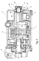
- FIG. 1 shows a longitudinal section through a starter device 1.
- This has a housing 2 in which a direct current motor 3 and an engagement relay 4 are accommodated.
- the DC motor 3 has a rotor 5 which acts on an output shaft 6, on the end 7 of which a pinion 8 is arranged in a rotationally fixed manner.
- the pinion 8 advances to the position 9 shown in broken lines in FIG.
- the engagement of relay 4 causes the pinion to move axially to position 9. This will be discussed in more detail below.
- the rotor 5 is provided with a commutator 11, to the segments 12 of which a rotor winding 13 is connected.
- the commutator 11 interacts with a carbon brush arrangement 14.
- a stator 15 with a stator winding 16 is provided, which lies opposite the rotor 5 with a small air gap.
- the rotor 5 has a rotor shaft 17 which is supported at one end 18 in a needle bearing 19 and covered by a housing cap 20.
- the the other end of the rotor shaft 17 has a central receiving bore 22 extending from its end face 21, into which one end 23 of the output shaft 6 engages.
- the other end of the rotor shaft 17 is mounted on the end 23 of the output shaft 6 via a needle bearing 31 which is arranged in the receiving bore 22.
- the lateral surface 24 of the end 25 of the rotor shaft 17 provided with the receiving bore 22 is designed as a sun gear 26 which meshes with planet gears 27 which are arranged on a planet carrier 28 (only one planet gear 27 is shown in FIG. 1).
- the planet gears 27 are arranged with the interposition of needle bearings on bearing pins 29.
- the planet gears 27 mesh with a ring gear 30 provided with internal teeth, which is arranged in a stationary manner in the housing 2.
- the end 23 of the output shaft 6 is mounted in the receiving bore of the axial web 39 via a needle bearing 37.
- the freewheel outer ring 35 is held by a deep groove ball bearing 38, which is arranged on the axial web 39 and is supported on the other hand in the housing 2 (fixed bearing).
- a cylindrical roller bearing 33 is provided — held by the housing 2, to which a sealing ring 34 is connected upstream — to the outside.
- the cylindrical roller bearing 33 guides the output shaft 6 both in the axial and in the radial direction.
- the planet carrier 28 is axially connected to a freewheel outer ring 35 via screws 36.
- the freewheel outer ring 35 belongs to a freewheel device 40 which is designed as a roller freewheel. It has spring-loaded rollers 41 which interact with an inner ring 42 of the freewheel device 40.
- the inner ring 42 is connected to the output shaft 6 via a steep thread 43.
- the output shaft 6 has a groove 44 in which a snap ring 45 is arranged.
- the snap ring 45 forms a stop which, in the event of an axial displacement of the output shaft 6 to be described in greater detail, cooperates with a step 46 of the inner ring 42.
- a retaining ring 47 which has a radial collar 48, is fastened on the output shaft 6. Furthermore, a snap ring 50, which supports a disk 51, lies in a groove 49 of the retaining ring 47. An annular channel 52 is thus formed between the disk 51 and the radial collar 48.
- the pinion 8 is rotatably but axially displaceably mounted. It is acted upon by a helical compression spring 54. This is preloaded when a tooth-on-tooth position results when the pinion 8 is engaged in the ring gear 10.
- the engagement relay 4 has a fixed relay winding 61 which interacts with an armature 62.
- the armature 62 is axially displaceably mounted and is pushed into the position shown in FIG. 1 by a return spring 112 in the form of a helical compression spring when the engagement relay 4 is not energized.
- the axis 63 has a contact element 66 at its one end region 65 on that can cooperate with electrical connections 67.
- the armature 62 is connected to a plunger 68 which projects into a housing space 69 of the housing 2.
- the plunger 68 interacts with an engagement lever 70 designed as a double lever, which is pivotably mounted approximately in its central region by means of a cross bolt 71.
- the cross pin 71 is held on a housing-side arm 72.
- the lower end 73 of the engagement lever 70 is provided with a projection 74 which engages in the annular channel 52.
- a driving head 76 is formed at the other end 75 of the engagement lever 70.
- a locking device 77 which is essentially formed by a bow spring 80, a control sleeve 108, a ring 117 and springs 99 and 112, prevents the pinion 8 from unintentionally moving in the direction of the ring gear 10 of the internal combustion engine, since this would damage the Parts could result.
- This unintentional axial movement could occur without a locking device 77 in that braking moments, which occur, for example, due to the bearings and shaft sealing rings, move the output shaft 6 into the single-track position, that is to say the return spring forces are smaller than the axial force components occurring on the high-helix thread.
- the driving head 76 does not completely fill the distance between the one side 119 of the ring 117 and an end face 120 of the control collar 108; rather, an empty path remains b.
- the steep thread 43 allows an axial displacement of the output shaft 6 by the dimension a.
- the receiving bore 22 in the rotor shaft 17 of the rotor 5 ends in an axial bore 131 in which a resilient contact member 132 is accommodated.
- the contact member 132 is designed as a thrust bolt 133.
- This has a circular cross section, which is dimensioned to the diameter of the axial bore 131 that the thrust pin 133 is axially displaceably guided in the axial bore 131.
- the side 134 of the thrust bolt 133 facing away from the output shaft 6 is acted upon by a compression spring 135 designed as a helical spring, that is to say that one end 136 of the compression spring 135 is supported on the thrust bolt 133 and the other end 137 of the compression spring 135 lies at the bottom 138 of the designed as a blind bore axial bore 131.
- the lateral surface 139 of the thrust bolt 133 has a radial collar 140 in the support region of the compression spring 135. As a result, the remaining area of the lateral surface 139 faces the axial bore 131 at a distance from the inner wall 141. The distance is dimensioned such that a snap ring 143 can be received there, which is inserted into an annular groove 142 formed on the inner wall 141.
- the snap ring 143 forms a stop for the Thrust bolt 133; that is, it limits the axial movement of the thrust bolt 133 caused by the compression spring 135 when the thrust bolt 133 is not acted upon.
- the side 144 of the starting bolt 133 facing the output shaft 6 has a central starting elevation 145.
- the arrangement is designed in such a way that, in the track position of the output shaft 6 shown in FIG. 1, its end face 146 acts on the run-up elevation 145 of the run-up bolt 133 in such a way that the latter is lifted from the snap ring 143 by a displacement path c.
- the compression spring 135 is compressed accordingly, so that a reaction force is exerted on the rotor 5 of the direct current motor 3.
- the displacement path c is approx. 2 to 3 mm.
- the rotor shaft 17 is guided in a rotor bearing 147, which is designed as a needle bearing 19. Between the end face 148 of the rotor 5 or commutator 11 and a housing region 149 of the starting device 1, a brake disk 151 provided with a braking surface 150 is arranged.
- the housing region 149 is formed by a contact surface 152 surrounding the rotor bearing 147.
- the starting device 1 operates as follows: For a starting process of the internal combustion engine (not shown), the engagement relay 4 is energized via a start switch. This causes the armature 62 to move to the right ( Figure 1), causing the control sleeve 108 runs against the bow spring 80 in such a way that it is radially expanded. As a result, the ring 117 is released. A relative movement between the control sleeve 108 and the ring 117 is possible while consuming the free travel b because the latter is mounted on the control sleeve 108 so as to be axially displaceable.
- the free travel b is used up, that is to say the left side of the driving head 76 is carried along by the control sleeve 108.
- the engagement lever 70 pivots clockwise around the cross pin 71.
- the projection 74 shifts the output shaft 6 in the direction of the ring gear 10, as a result of which the pinion 8 can engage in the toothing of the ring gear 10.
- the engagement forces ensure that the pinion 8 now moves completely into the ring gear 10, the output shaft 6 extending axially to the end position due to the steep thread 43, so that — as a result — the position 9 of the pinion shown in broken lines in FIG. 1 8 is taken.
- the engagement relay 4 drops out.
- the return movement is supported by the return springs 64 and 112.
- the ring 117 comes against the driving head 76 of the engagement lever 70, so that the engagement lever 70 pivots counterclockwise, whereby the pinion 8 is returned to the position shown in solid line in FIG. Since the internal combustion engine, which is now in operation, "overtakes" the rotation of the pinion 8 in the final stage of the starting process, the disengagement process is supported by the steep thread 43.
Landscapes
- Engineering & Computer Science (AREA)
- Chemical & Material Sciences (AREA)
- Combustion & Propulsion (AREA)
- Mechanical Engineering (AREA)
- General Engineering & Computer Science (AREA)
- Connection Of Motors, Electrical Generators, Mechanical Devices, And The Like (AREA)
- Braking Arrangements (AREA)
Abstract
Description
- Die Erfindung betrifft eine Andrehvorrichtung mit einer ein Ritzel für den Antrieb eines Zahnkranzes einer Brennkraftmaschine tragenden, von einem Rotor angetriebenen Abtriebswelle, die für den Ein- beziehungsweise Ausspurvorgang des Ritzels axial verschieblich gelagert ist, nach Anspruch 1, 1.Teil (vergl. FR-A-2536 466).
- In der Kraftfahrzeugtechnik dienen derartige Andrehvorrichtungen zum Start der Fahrzeug-Brennkraftmaschinen. Für den Startvorgang der Fahrzeug-Brennkraftmaschinen muß ein angetriebenes Ritzel in einen Zahnkranz der Brennkraftmaschine einspuren. Für die hierzu erforderliche Axialbewegung des Ritzels ist eine dieses tragende Abtriebswelle axial verschieblich gelagert. Wird der Startvorgang beendet, so spurt das Ritzel aus dem Zahnkranz wieder aus, wobei die Abtriebswelle in ihre Ausgangsstellung (Ausspurstellung) zurücktritt. Nachteilig ist, wenn nach dem Ausspuren das Ritzel noch eine längere Zeit nachläuft, da dann bei einem möglicherweise erfolgenden weiteren Startvorgang kein sauberes Einspuren erfolgt, sondern durch eine zu große Relativbewegung zwischen Ritzel und Zahnkranz eine Beschädigung erfolgen könnte. Besonders lang ist die Auslaufzeit bei Getriebe-Andrehvorrichtungen gegenüber Direkt-Andrehvorrichtungen (ohne Getriebestufe), da die Trägheitsmomente durch das Übersetzungsverhältnis im Quadrat ansteigen.
- Die erfindungsgemäße Andrehvorrichtung mit den im Hauptanspruch genannten Merkmalen hat demgegenüber den Vorteil, daß lange Auslaufzeiten des Ritzels beim Beenden des Startvorgangs verhindert sind. Erfindungsgemäß wird durch die sich in die Ausspurstellung zurückbewegende Abtriebswelle selbsttätig eine Bremswirkung ausgelöst, die den Rotor des Antriebs und damit auch das Ritzel abbremst. Die erfindungsgemäße Lehre schlägt dafür vor, daß die Rückbewegung der Abtriebswelle derart auf den Rotor übertragen wird, so daß sich dieser ebenfalls axial verlagert und dabei gegen die Bremsflache tritt. Bei Getriebe-Andrehvorrichtungen ist ein derartiges Abbremsen besonders effektiv, da der Rotor ein Element darstellt, dem ein relativ niedriges Drehmoment zugeordnet ist. Somit führen auch schon relativ kleine Bremskräfte zu großer Wirkung.
- Nach der Erfindung ist vorgesehen, daß die Abtriebswelle gegen ein federndes Anlageglied des Rotors tritt. Diese federnde Abstützung zwischen Abtriebswelle und Rotor gleicht einerseits Toleranzen aus und führt dennoch zur Übertragung von Axialkräften auf den Rotor.
- Vorteilhaft ist es, wenn das Anlageglied koaxial zum Rotor angeordnet ist. Hierdurch sind Unwuchten vermieden und auch kleine Trägheitsmomente erzielt.
- Um die federnde Wirkung des Anlageglieds zu erhalten, ist bevorzugt zwischen Anlageglied und Rotor eine Druckfeder angeordnet.
- Ein besonders platzsparender und dennoch einfacher Aufbau ergibt sich, wenn das Anlageglied in einer Axialbohrung einer Rotorwelle axial verschiebbar geführt ist. Insbesondere kann das Anlageglied als Anlaufbolzen ausgebildet sein. Dieser hat vorzugsweise einen kreisförmigen Querschnitt, wobei sich seine Mittelachse koaxial zur Rotorachse erstreckt.
- Eine gute Bremswirkung läßt sich dann erzielen, wenn die Bremsfläche an einer Bremsscheibe ausgebildet ist. Diese befindet sich vorzugsweise zwischen der Stirnseite eines dem Rotor zugeordneten Kommutators und einem Gehäusebereich der Andrehvorrichtung.
- Insbesondere ist vorgesehen, daß der Gehäusebereich von einer ein Rotorlager umgebenden Anlagefläche gebildet ist.
- Die Erfindung wird im folgenden anhand der Figuren näher erläutert. Es zeigen:
- Figur 1
- ein Längsschnitt durch eine Andrehvorrichtung und
- Figur 2
- ein Ausschnitt aus der Darstellung der Figur 1, wobei eine Einspurstellung eingenommen ist.
- Die Figur 1 zeigt einen Längsschnitt durch eine Andrehvorrichtung 1. Diese weist ein Gehäuse 2 auf, in dem ein Gleichstrommotor 3 und ein Einrückrelais 4 untergebracht sind. Der Gleichstrommotor 3 weist einen Rotor 5 auf, der auf eine Abtriebswelle 6 wirkt, auf dessen Ende 7 ein Ritzel 8 drehfest angeordnet ist. Für den Anlaßbetrieb einer nicht dargestellten Brennkraftmaschine rückt das Ritzel 8 in die in der Figur 1 gestrichelt eingezeichnete Position 9 vor und spurt dabei in einen Zahnkranz 10 der Brennkraftmaschine ein. Die axiale Verlagerung des Ritzels in die Position 9 wird durch das Einrückrelais 4 veranlaßt. Hierauf wird im nachfolgenden noch näher eingegangen.
- Der Rotor 5 ist mit einem Kommutator 11 versehen, an dessen Segmenten 12 eine Rotorwicklung 13 angeschlossen ist. Der Kommutator 11 wirkt mit einer Kohlebürstenanordnung 14 zusammen. Ferner ist ein Stator 15 mit Statorwicklung 16 vorgesehen, der dem Rotor 5 mit geringem Luftspalt gegenüberliegt.
- Der Rotor 5 weist eine Rotorwelle 17 auf, die an ihrem einen Ende 18 in einem Nadellager 19 gelagert und von einer Gehäusekappe 20 überfangen ist. Das andere Ende der Rotorwelle 17 weist eine von ihrer Stirnseite 21 ausgehende, zentrale Aufnahmebohrung 22 auf, in die das eine Ende 23 der Abtriebswelle 6 eingreift. Das andere Ende der Rotorwelle 17 ist über ein Nadellager 31, das in der Aufnahmebohrung 22 angeordnet ist, auf dem Ende 23 der Abtriebswelle 6 gelagert. Die Mantelfläche 24 des mit Aufnahmebohrung 22 versehenen Endes 25 der Rotorwelle 17 ist als Sonnenrad 26 ausgebildet, das mit Planetenrädern 27 kämmt, die auf einem Planetenträger 28 angeordnet sind (in der Figur 1 ist lediglich ein Planetenrad 27 dargestellt). Die Planetenräder 27 sind unter Zwischenschaltung von Nadellager auf Lagerstiften 29 angeordnet.
- Ferner kämmen die Planetenräder 27 mit einem mit Innenverzahnung versehenen Hohlrad 30, das ortsfest im Gehäuse 2 angeordnet ist.
- Das Ende 23 der Abtriebswelle 6 ist über ein Nadellager 37 in der Aufnahmebohrung des Axialsteges 39 gelagert. Der Freilaufaußenring 35 wird durch ein Rillenkugellager 38, das auf dem Axialsteg 39 angeordnet und sich andererseits im Gehäuse 2 abstützt, gehalten (Festlager). Im gegenüberliegenden Endbereich 32 der Abtriebswelle 6 ist -vom Gehäuse 2 gehalten- ein Zylinderrollenlager 33 vorgesehen, dem -nach außen- ein Simmerring 34 vorgeschaltet ist. Das Zylinderrollenlager 33 führt die Abtriebswelle 6 sowohl in axialer als auch in radialer Richtung.
- Der Planetenträger 28 ist axial mit einem Freilaufaußenring 35 über Schrauben 36 verbunden.
- Der Freilaufaußenring 35 gehört einer Freilaufeinrichtung 40 an, die als Rollenfreilauf ausgebildet ist. Sie weist federbeaufschlagte Rollen 41 auf, die mit einem Innenring 42 der Freilaufeinrichtung 40 zusammenwirken. Der Innenring 42 steht über ein Steilgewinde 43 mit der Abtriebswelle 6 in Verbindung. Ferner weist die Abtriebswelle 6 eine Nut 44 auf, in der ein Sprengring 45 angeordnet ist. Der Sprengring 45 bildet einen Anschlag, der -bei einer noch näher zu beschreibenden- Axialverlagerung der Abtriebswelle 6 mit einer Stufe 46 des Innenrings 42 zusammenwirkt.
- Auf der Abtriebswelle 6 ist ein Haltering 47 befestigt, der einen Radialkragen 48 aufweist. Ferner liegt in einer Nut 49 des Halterings 47 ein Sprengring 50 ein, der eine Scheibe 51 abstützt. Zwischen Scheibe 51 und Radialkragen 48 wird somit ein Ringkanal 52 ausgebildet.
- Am Ende 7 der Abtriebswelle 6 ist das Ritzel 8 drehfest, jedoch axial verschieblich gelagert. Es wird von einer Schraubendruckfeder 54 beaufschlagt. Diese wird vorgespannt, wenn sich beim Einspuren des Ritzels 8 in den Zahnkranz 10 eine Zahn-Auf-Zahn-Stellung ergibt.
- Das Einrückrelais 4 weist eine ortsfeste Relaiswicklung 61 auf, die mit einem Anker 62 zusammenwirkt. Der Anker 62 ist axial verschieblich gelagert und wird von einer als Schraubendruckfeder ausgebildeten Rückstellfeder 112 im nicht erregten Zustand des Einrückrelais' 4 in die in der Figur 1 dargestellte Position gedrängt. Die Achse 63 weist an ihrem einen Endbereich 65 ein Kontaktelement 66 auf, daß mit elektrischen Anschlüssen 67 zusammenwirken kann.
- Der Anker 62 ist mit einem Stößel 68 verbunden, der in einen Gehäuseraum 69 des Gehäuses 2 hineinragt. Der Stößel 68 wirkt mit einem als Doppelhebel ausgebildeten Einrückhebel 70 zusammen, der etwa in seinem mittleren Bereich mittels eines Querbolzens 71 schwenkbeweglich gelagert ist. Der Querbolzens 71 wird an einem gehäuseseitigen Ausleger 72 gehalten. Das untere Ende 73 des Einrückhebels 70 ist mit einem Vorsprung 74 versehen, der in den Ringkanal 52 eingreift. Am anderen Ende 75 des Einrückhebels 70 ist ein Mitnahmekopf 76 ausgebildet. Durch Verlagerung des Stößels 68 wird der Einrückhebel 70 mitgenommen, wodurch eine Axialverlagerung der Abtriebswelle 6 erfolgt. Im nicht erregten Zustand des Einrückrelais' 4 ist dafür Sorge zu tragen, daß das Ritzel 8 die in der Figur 1 mit durchgezogenen Linien dargestellte Position nicht verläßt. Eine Verriegelungsvorrichtung 77, die im wesentlichen von einer Bügelfeder 80, einer Steuerhülse 108, einem Ring 117 sowie Federn 99 und 112 gebildet ist, verhindert, daß sich das Ritzel 8 unbeabsichtigt in Richtung auf den Zahnkranz 10 der Brennkraftmaschine bewegt, da dies zur Beschädigung der Teile führen könnte. Diese unbeabsichtigte Axialbewegung könnte ohne Verriegelungsvorrichtung 77 dadurch eintreten, daß bremsende Momente, die z.B. durch die Lager und Wellendichtringe auftreten, die Abtriebswelle 6 in Einspurposition bewegen, das heißt, die Rückstellfederkräfte sind kleiner als die am Steilgewinde auftretenden Axialkraftkomponenten.
- Aus der Figur 1 ist ersichtlich, daß der Mitnahmekopf 76 den Abstand zwischen der einen Seite 119 des Rings 117 und einer Stirnfläche 120 des Steuerkragens 108 nicht voll ausfüllt; vielmehr verbleibt ein Leerweg b.
- Das Steilgewinde 43 erlaubt eine Axialverlagerung der Abtriebswelle 6 um das Maß a.
- Die Aufnahmebohrung 22 in der Rotorwelle 17 des Rotors 5 läuft in einer Axialbohrung 131 aus, in der ein federndes Anlageglied 132 untergebracht ist. Das Anlageglied 132 ist als Anlaufbolzen 133 ausgebildet. Dieser besitzt einen kreisförmigen Querschnitt, der derart zum Durchmessermaß der Axialbohrung 131 bemessen ist, daß der Anlaufbolzen 133 axial verschiebbar in der Axialbohrung 131 geführt wird. Die der Abtriebswelle 6 abgewandte Seite 134 des Anlaufbolzens 133 wird von einer als Schraubenfeder ausgebildeten Druckfeder 135 beaufschlagt, das heißt, das eine Ende 136 der Druckfeder 135 stützt sich an dem Anlaufbolzen 133 ab und das andere Ende 137 der Druckfeder 135 liegt am Grund 138 der als Sackbohrung ausgebildeten Axialbohrung 131 an.
- Die Mantelfläche 139 des Anlaufbolzens 133 weist im Abstützbereich der Druckfeder 135 einen Radialkragen 140 auf. Hierdurch steht der übrige Bereich der Mantelfläche 139 mit Abstand der Innenwandung 141 der Axialbohrung 131 gegenüber. Der Abstand ist gerade so bemessen, daß dort ein Sprengring 143 aufgenommen werden kann, der in eine an der Innenwandung 141 ausgebildeten Ringnut 142 eingesetzt ist. Der Sprengring 143 bildet einen Anschlag für den Anlaufbolzen 133; das heißt, er begrenzt bei nicht beaufschlagtem Anlaufbolzen 133 die durch die Druckfeder 135 bewirkte Axialbewegung des Anlaufbolzens 133.
- Die der Abtriebswelle 6 zugekehrte Seite 144 des Anlaufbolzens 133 weist eine zentrale Anlauferhebung 145 auf. Die Anordnung ist nun derart ausgebildet, daß in der in der Figur 1 dargestellten Ausspurstellung der Abtriebswelle 6 deren Stirnseite 146 die Anlauferhebung 145 des Anlaufbolzens 133 derart beaufschlagt, daß letzterer um einen Verschiebeweg c von dem Sprengring 143 abgehoben wird. Hierdurch wird die Druckfeder 135 entsprechend komprimiert, so daß eine Reaktionskraft auf den Rotor 5 des Gleichstrommotors 3 ausgeübt wird. Der Verschiebeweg c beträgt ca. 2 bis 3 mm.
- Am kommutatorseitigen Ende 18 ist die Rotorwelle 17 in einem Rotorlager 147 geführt, das als Nadellager 19 ausgebildet ist. Zwischen der Stirnseite 148 des Rotors 5 beziehungsweise Kommutators 11 und einem Gehäusebereich 149 der Andrehvorrichtung 1 ist eine mit Bremsfläche 150 versehene Bremsscheibe 151 angeordnet. Der Gehäusebereich 149 wird von einer das Rotorlager 147 umgebenden Anlagefläche 152 gebildet.
- Die erfindungsgemäße Andrehvorrichtung 1 arbeitet folgendermaßen:
Für einen Startvorgang der (nicht dargestellten) Brennkraftmaschine wird über einen Startschalter das Einrückrelais 4 erregt. Dies führt dazu, daß sich der Anker 62 nach rechts (Figur 1) bewegt, wodurch die Steuerhülse 108 derart gegen die Bügelfeder 80 anläuft, daß diese radial aufgespreizt wird. Hierdurch wird der Ring 117 freigegeben. Eine Relativbewegung zwischen der Steuerhülse 108 und dem Ring 117 ist unter Aufzehrung des Leerweges b deshalb möglich, weil letzterer axial verschieblich auf der Steuerhülse 108 gelagert ist. Nimmt die Bügelfeder 80 ihre aufgespreizte Stellung ein, so ist der Leerweg b aufgebraucht, das heißt, die linke Seite des Mitnahmekopfes 76 wird von der Steuerhülse 108 mitgenommen. Der Einrückhebel 70 führt eine Schwenkbewegung im Uhrzeigersinn um den Querbolzen 71 herum aus. Dabei verlagert der Vorsprung 74 die Abtriebswelle 6 in Richtung auf den Zahnkranz 10, wodurch das Ritzel 8 in die Zahnung des Zahnkranzes 10 einspuren kann. Die Einspurkräfte sorgen dafür, daß nunmehr das Ritzel 8 vollständig in den Zahnkranz 10 einfährt, wobei aufgrund des Steilgewindes 43 die Abtriebswelle 6 bis in Endposition axial herausfährt, so daß -im Ergebnis- die in der Figur 1 mit gestrichelten Linien eingezeichnete Position 9 vom Ritzel 8 eingenommen wird. Da durch die Anzugsbewegung des Einrückrelais' 4 das Kontaktelement 66 in Verbindung zu den elektrischen Anschlüssen 67 tritt, wird der Gleichstrommotor 3 erregt, das heißt, der Rotor 5 beginnt zu drehen, wodurch das Ritzel 8 über das aus Sonnenrad 26, Planetenrädern 27 und Hohlrad 30 gebildete Untersetzungsgetriebe mitgenommen wird. - Wird der Startvorgang beendet, so fällt das Einrückrelais 4 ab. Die Abfallbewegung wird von den Rückstellfedern 64 und 112 unterstützt. Dabei tritt der Ring 117 gegen den Mitnahmekopf 76 des Einrückhebels 70, so daß der Einrückhebel 70 entgegen dem Uhrzeigersinn verschwenkt, wodurch das Ritzel 8 in die in der Figur 1 mit durchgezogener Linie dargestellte Position zurückgeholt wird. Da im Endstadium des Startvorgangs die nunmehr im Betrieb befindliche Brennkraftmaschine die Drehung des Ritzels 8 "überholt" wird durch das Steilgewinde 43 der Ausspurvorgang unterstützt.
- Ist wieder die Ausspurposition (Ruheposition) eingenommen (Figur 1), so befindet sich auch die Bügelfeder 80 wieder in Ausgangsstellung, das heißt, sie sichert den Ring 117, so daß der Einrückhebel 70 in der in der Figur 1 dargestellten Position fixiert ist. Damit ist eine unbeabsichtigte Axialverlagerung der Abtriebswelle 6 verhindert.
- Verlagert sich die Abtriebswelle 6 -wie beschrieben- für den Startvorgang der Brennkraftmaschine in ihre Einspurstellung, die in der Figur 2 dargestellt ist, so entlastet die Stirnseite 146 der Abtriebswelle 6 den Anlaufbolzen 133, so daß er durch die Druckfeder 135 mit seinem Radialkragen 140 gegen den Sprengring 143 gedrängt wird. Der Rotor 5 des Gleichstrommotors 3 unterliegt daher keiner durch den Anlaufbolzen verursachter Axialkraftbeaufschlagung mehr. Wird der Startvorgang beendet, so tritt die Abtriebswelle 6 in ihre in der Figur 1 dargestellte Ausrückstellung zurück, wodurch die Stirnseite 146 den Anlaufbolzen 133 unter Komprimierung der Druckfeder 135 in die in der Figur 1 dargestellte Stellung zurückdrängt. Hierdurch wird eine Reaktionskraft auf den Rotor 5 ausgeübt, wodurch die Stirnseite 148 des Kommutators 11 gegen die Bremsscheibe 151 gedrängt wird. Die Bremsscheibe 151 wiederum stützt sich an der Anlagefläche 152 des Gehäuses 2 ab. Hierdurch erfolgt eine Abbremsung der Drehbewegung des Rotors 5. Dieser Bremsvorgang ist besonders bei der dargestellten Getriebe-Andrehvorrichtung effektiv, da er an einer Stelle erfolgt, der ein relativ niedriges Drehmoment zugeordnet ist. Die Folge ist eine sehr kurze Auslaufzeit der Andrehvorrichtung.
Claims (9)
- Andrehvorrichtung mit einer ein Ritzel für den Antrieb eines Zahnkranzes einer Brennkraftmaschine tragenden, von einem Rotor angetriebenen Abtriebswelle, die für den Ein- bzw. Ausspurvorgang des Ritzels axial verschiebbar gelagert ist, in Ausspurstellung den Rotor (5) axial derart beaufschlagt, daß er (5) federelastisch gegen eine Bremsfläche (150) tritt, dadurch gekennzeichnet, daß die Abtriebswelle (6) gegen ein axial federndes Anlageglied (132) des Rotors (5) tritt.
- Andrehvorrichtung nach Anspruch 1, dadurch gekennzeichnet, daß das Anlageglied (132) koaxial zum Rotor (5) angeordnet ist.
- Andrehvorrichtung nach einem der vorhergehenden Ansprüche, dadurch gekennzeichnet, daß zwischen Anlageglied (132) und Rotor (5) eine Druckfeder (135) angeordnet ist.
- Andrehvorrichtung nach einem der vorhergehenden Ansprüche, dadurch gekennzeichnet, daß das Anlageglied (132) in einer Axialbohrung (131) einer Rotorwelle (17) axial verschiebbar geführt ist.
- Andrehvorrichtung nach einem der vorhergehenden Ansprüche, dadurch gekennzeichnet, daß das Anlageglied (132) als Anlaufbolzen (133) für die Antriebswelle (6) ausgebildet ist.
- Andrehvorrichtung nach einem der vorhergehenden Ansprüche, dadurch gekennzeichnet, daß die Bremsfläche (150) an einer Bremsscheibe (151) ausgebildet ist.
- Andrehvorrichtung nach Anspruch 6, dadurch gekennzeichnet, daß die Bremsscheibe (151) gehäusefest zwischen der Stirnseite (146) eines dem Rotor (5) zugeordneten Kommutators (11) und einem Gehausebereich (149) der Andrehvorrichtung (1) angeordnet ist.
- Andrehvorrichtung nach Anspruch 7, dadurch gekennzeichnet, daß der Gehäusebereich (149) von einer ein Rotorlager (147) umgebenden Anlagefläche (152) gebildet ist.
- Andrehvorrichtung nach einem der vorhergehenden Ansprüche, gekennzeichnet durch die Ausbildung als Getriebe-Andrehvorrichtung.
Applications Claiming Priority (3)
| Application Number | Priority Date | Filing Date | Title |
|---|---|---|---|
| DE4006797 | 1990-03-03 | ||
| DE4006797A DE4006797A1 (de) | 1990-03-03 | 1990-03-03 | Andrehvorrichtung mit bremseinrichtung |
| PCT/DE1991/000140 WO1991014094A1 (de) | 1990-03-03 | 1991-02-22 | Andrehvorrichtung mit bremseinrichtung |
Publications (2)
| Publication Number | Publication Date |
|---|---|
| EP0518878A1 EP0518878A1 (de) | 1992-12-23 |
| EP0518878B1 true EP0518878B1 (de) | 1994-10-05 |
Family
ID=6401408
Family Applications (1)
| Application Number | Title | Priority Date | Filing Date |
|---|---|---|---|
| EP91903883A Expired - Lifetime EP0518878B1 (de) | 1990-03-03 | 1991-02-22 | Andrehvorrichtung mit bremseinrichtung |
Country Status (11)
| Country | Link |
|---|---|
| US (1) | US5321987A (de) |
| EP (1) | EP0518878B1 (de) |
| JP (1) | JPH05504808A (de) |
| AU (1) | AU638802B2 (de) |
| BR (1) | BR9106109A (de) |
| CZ (1) | CZ280180B6 (de) |
| DE (2) | DE4006797A1 (de) |
| ES (1) | ES2063495T3 (de) |
| HU (1) | HU208725B (de) |
| RU (1) | RU2048653C1 (de) |
| WO (1) | WO1991014094A1 (de) |
Families Citing this family (8)
| Publication number | Priority date | Publication date | Assignee | Title |
|---|---|---|---|---|
| US5953955A (en) * | 1994-11-24 | 1999-09-21 | Nippondenso Co., Ltd. | Starter with planetary gear speed reduction mechanism |
| DE19911161C2 (de) * | 1999-03-11 | 2003-10-30 | Bosch Gmbh Robert | Elektromechanisches Vor- und Rückspurprinzip für Koaxialstarter |
| RU2177654C2 (ru) * | 1999-11-26 | 2001-12-27 | ОАО "Димитровградский автоагрегатный завод" | Устройство безопасности для пускового устройства автомобиля |
| RU2451206C2 (ru) * | 2009-03-10 | 2012-05-20 | Федеральное государственное образовательное учреждение высшего профессионального образования "Военный авиационный инженерный университет" (г. Воронеж) Министерства обороны Российской Федерации | Механизм включения стартера |
| DE102009027859B4 (de) * | 2009-07-21 | 2019-12-24 | Seg Automotive Germany Gmbh | Elektrische Maschine mit kommutatorseitigem Lager |
| FR2990729B1 (fr) * | 2012-05-16 | 2015-11-13 | Valeo Equip Electr Moteur | Demarreur a lanceur muni d'une roue libre immobile en translation |
| CN103388527B (zh) * | 2013-07-30 | 2016-05-04 | 长城汽车股份有限公司 | 一种汽车发动机熄火后曲轴位置限定系统 |
| CN106014748A (zh) * | 2016-07-14 | 2016-10-12 | 上海法雷奥汽车电器系统有限公司 | 一种减速起动机 |
Family Cites Families (11)
| Publication number | Priority date | Publication date | Assignee | Title |
|---|---|---|---|---|
| FR1107059A (fr) * | 1950-12-11 | 1955-12-28 | Magneti Marelli Spa | Perfectionnements aux démarreurs électriques pour moteurs |
| US2759363A (en) * | 1952-04-21 | 1956-08-21 | Leo F Phaneuf | Switch control apparatus |
| US2777328A (en) * | 1954-12-30 | 1957-01-15 | Caterpillar Tractor Co | Control for starter pinion engaging mechanism |
| DE2448069A1 (de) * | 1974-10-09 | 1976-04-22 | Bosch Gmbh Robert | Andrehvorrichtung fuer brennkraftmaschinen |
| DE2460114A1 (de) * | 1974-12-19 | 1976-06-24 | Bosch Gmbh Robert | Andrehvorrichtung fuer brennkraftmaschinen |
| GB2037373B (en) * | 1978-11-10 | 1983-02-09 | Hitachi Ltd | Engine starter |
| US4412457A (en) * | 1981-04-29 | 1983-11-01 | General Motors Corporation | In-line engine cranking motor drive having reduction gear set |
| FR2536466B1 (fr) * | 1982-11-24 | 1986-11-14 | Paris & Du Rhone | Dispositif de freinage pour demarreur de moteur a combustion interne |
| JPS61106974A (ja) * | 1984-10-30 | 1986-05-24 | Nippon Denso Co Ltd | 遊星歯車減速機構付スタ−タ |
| JPS63209448A (ja) * | 1987-02-23 | 1988-08-31 | Mitsubishi Electric Corp | エンジン用スタ−タ装置 |
| JPH01247762A (ja) * | 1988-03-28 | 1989-10-03 | Hitachi Ltd | 遊星歯車減速機付スタータ |
-
1990
- 1990-03-03 DE DE4006797A patent/DE4006797A1/de not_active Ceased
-
1991
- 1991-02-22 JP JP3503956A patent/JPH05504808A/ja active Pending
- 1991-02-22 DE DE59103176T patent/DE59103176D1/de not_active Expired - Fee Related
- 1991-02-22 WO PCT/DE1991/000140 patent/WO1991014094A1/de not_active Ceased
- 1991-02-22 US US07/852,125 patent/US5321987A/en not_active Expired - Fee Related
- 1991-02-22 ES ES91903883T patent/ES2063495T3/es not_active Expired - Lifetime
- 1991-02-22 RU SU915053134A patent/RU2048653C1/ru active
- 1991-02-22 EP EP91903883A patent/EP0518878B1/de not_active Expired - Lifetime
- 1991-02-22 BR BR919106109A patent/BR9106109A/pt not_active IP Right Cessation
- 1991-02-22 AU AU72400/91A patent/AU638802B2/en not_active Ceased
- 1991-02-22 HU HU9202826A patent/HU208725B/hu not_active IP Right Cessation
- 1991-02-28 CZ CS91527A patent/CZ280180B6/cs not_active IP Right Cessation
Also Published As
| Publication number | Publication date |
|---|---|
| CZ280180B6 (cs) | 1995-11-15 |
| JPH05504808A (ja) | 1993-07-22 |
| EP0518878A1 (de) | 1992-12-23 |
| WO1991014094A1 (de) | 1991-09-19 |
| BR9106109A (pt) | 1993-02-24 |
| RU2048653C1 (ru) | 1995-11-20 |
| AU7240091A (en) | 1991-10-10 |
| DE4006797A1 (de) | 1991-09-12 |
| AU638802B2 (en) | 1993-07-08 |
| ES2063495T3 (es) | 1995-01-01 |
| HUT61612A (en) | 1993-01-28 |
| US5321987A (en) | 1994-06-21 |
| HU208725B (en) | 1993-12-28 |
| DE59103176D1 (de) | 1994-11-10 |
| HU9202826D0 (en) | 1992-12-28 |
Similar Documents
| Publication | Publication Date | Title |
|---|---|---|
| EP0518877B1 (de) | Andrehvorrichtung in kompaktbauweise | |
| DE69507229T2 (de) | Anlasser | |
| EP0518895B1 (de) | Andrehvorrichtung mit abtriebswellenverriegelung | |
| DE102008000883A1 (de) | Startvorrichtung | |
| DE69302942T2 (de) | Anlassmotor | |
| DE10016706A1 (de) | Startvorrichtung | |
| EP2379875A1 (de) | Verfahren und vorrichtung für start-stopp-anlagen von brennkraftmaschinen in kraftfahrzeugen | |
| EP2435688B1 (de) | Verfahren zur mechanischen synchronisation zweier sich drehender, achsversetzter stirnzahnräder | |
| WO2008145642A1 (de) | System aus startvorrichtung und brennkraftmaschine, startvorrichtung sowie brennkraftmaschine | |
| EP2087229A1 (de) | Starter zum andrehen einer brennkraftmaschine mit ritzelwellenabstützung | |
| EP2172645B1 (de) | Startvorrichtung | |
| WO1987000594A1 (fr) | Transmission a ressort enroule | |
| DE69201872T2 (de) | Anlasservorrichtung. | |
| WO1991014094A1 (de) | Andrehvorrichtung mit bremseinrichtung | |
| DE10135141A1 (de) | Starter | |
| EP2504563B1 (de) | Geräuschoptimierte startvorrichtung | |
| DE4030813C2 (de) | Anlasser der Koaxial-Bauart für Brennkraftmaschinen | |
| DE68901861T2 (de) | Ritzeleinrueckvorrichtung fuer anlasser. | |
| DE102011103135A1 (de) | Ventilantrieb mit einem Freilauf für ein Ventil, inbesondere Gasventil | |
| EP2472101B1 (de) | Vorrichtung zur Sicherung eines Ritzels | |
| DE10336521A1 (de) | Starter | |
| DE2306364A1 (de) | Andrehvorrichtung fuer brennkraftmaschinen | |
| DE19727545B4 (de) | Andrehvorrichtung für Brennkraftmaschinen | |
| DE29719524U1 (de) | Andrehvorrichtung für Brennkraftmaschinen | |
| DE10258908A1 (de) | Freilaufkupplungs-Baueinheit für den Starter eines Verbrennungsmotors |
Legal Events
| Date | Code | Title | Description |
|---|---|---|---|
| PUAI | Public reference made under article 153(3) epc to a published international application that has entered the european phase |
Free format text: ORIGINAL CODE: 0009012 |
|
| 17P | Request for examination filed |
Effective date: 19920730 |
|
| AK | Designated contracting states |
Kind code of ref document: A1 Designated state(s): DE ES FR GB IT SE |
|
| 17Q | First examination report despatched |
Effective date: 19940328 |
|
| GRAA | (expected) grant |
Free format text: ORIGINAL CODE: 0009210 |
|
| AK | Designated contracting states |
Kind code of ref document: B1 Designated state(s): DE ES FR GB IT SE |
|
| ET | Fr: translation filed | ||
| GBT | Gb: translation of ep patent filed (gb section 77(6)(a)/1977) |
Effective date: 19941012 |
|
| REF | Corresponds to: |
Ref document number: 59103176 Country of ref document: DE Date of ref document: 19941110 |
|
| ITF | It: translation for a ep patent filed | ||
| REG | Reference to a national code |
Ref country code: ES Ref legal event code: FG2A Ref document number: 2063495 Country of ref document: ES Kind code of ref document: T3 |
|
| EAL | Se: european patent in force in sweden |
Ref document number: 91903883.6 |
|
| PLBE | No opposition filed within time limit |
Free format text: ORIGINAL CODE: 0009261 |
|
| STAA | Information on the status of an ep patent application or granted ep patent |
Free format text: STATUS: NO OPPOSITION FILED WITHIN TIME LIMIT |
|
| 26N | No opposition filed | ||
| PGFP | Annual fee paid to national office [announced via postgrant information from national office to epo] |
Ref country code: ES Payment date: 19990208 Year of fee payment: 9 |
|
| PGFP | Annual fee paid to national office [announced via postgrant information from national office to epo] |
Ref country code: GB Payment date: 19990210 Year of fee payment: 9 |
|
| PG25 | Lapsed in a contracting state [announced via postgrant information from national office to epo] |
Ref country code: GB Free format text: LAPSE BECAUSE OF NON-PAYMENT OF DUE FEES Effective date: 20000222 |
|
| PG25 | Lapsed in a contracting state [announced via postgrant information from national office to epo] |
Ref country code: ES Free format text: LAPSE BECAUSE OF NON-PAYMENT OF DUE FEES Effective date: 20000223 |
|
| PGFP | Annual fee paid to national office [announced via postgrant information from national office to epo] |
Ref country code: SE Payment date: 20000223 Year of fee payment: 10 |
|
| GBPC | Gb: european patent ceased through non-payment of renewal fee |
Effective date: 20000222 |
|
| PGFP | Annual fee paid to national office [announced via postgrant information from national office to epo] |
Ref country code: FR Payment date: 20010216 Year of fee payment: 11 |
|
| PG25 | Lapsed in a contracting state [announced via postgrant information from national office to epo] |
Ref country code: SE Free format text: LAPSE BECAUSE OF NON-PAYMENT OF DUE FEES Effective date: 20010223 |
|
| PGFP | Annual fee paid to national office [announced via postgrant information from national office to epo] |
Ref country code: DE Payment date: 20010420 Year of fee payment: 11 |
|
| EUG | Se: european patent has lapsed |
Ref document number: 91903883.6 |
|
| REG | Reference to a national code |
Ref country code: ES Ref legal event code: FD2A Effective date: 20010910 |
|
| PG25 | Lapsed in a contracting state [announced via postgrant information from national office to epo] |
Ref country code: DE Free format text: LAPSE BECAUSE OF NON-PAYMENT OF DUE FEES Effective date: 20020903 |
|
| PG25 | Lapsed in a contracting state [announced via postgrant information from national office to epo] |
Ref country code: FR Free format text: LAPSE BECAUSE OF NON-PAYMENT OF DUE FEES Effective date: 20021031 |
|
| REG | Reference to a national code |
Ref country code: FR Ref legal event code: ST |
|
| PG25 | Lapsed in a contracting state [announced via postgrant information from national office to epo] |
Ref country code: IT Free format text: LAPSE BECAUSE OF NON-PAYMENT OF DUE FEES Effective date: 20050222 |