EP0517618A1 - Lasttrenngerät für elektrische Schaltung - Google Patents
Lasttrenngerät für elektrische Schaltung Download PDFInfo
- Publication number
- EP0517618A1 EP0517618A1 EP92420154A EP92420154A EP0517618A1 EP 0517618 A1 EP0517618 A1 EP 0517618A1 EP 92420154 A EP92420154 A EP 92420154A EP 92420154 A EP92420154 A EP 92420154A EP 0517618 A1 EP0517618 A1 EP 0517618A1
- Authority
- EP
- European Patent Office
- Prior art keywords
- movable contact
- temperature coefficient
- positive temperature
- circuit
- cut
- Prior art date
- Legal status (The legal status is an assumption and is not a legal conclusion. Google has not performed a legal analysis and makes no representation as to the accuracy of the status listed.)
- Granted
Links
Images
Classifications
-
- H—ELECTRICITY
- H01—ELECTRIC ELEMENTS
- H01H—ELECTRIC SWITCHES; RELAYS; SELECTORS; EMERGENCY PROTECTIVE DEVICES
- H01H9/00—Details of switching devices, not covered by groups H01H1/00 - H01H7/00
- H01H9/30—Means for extinguishing or preventing arc between current-carrying parts
- H01H9/42—Impedances connected with contacts
-
- H—ELECTRICITY
- H01—ELECTRIC ELEMENTS
- H01H—ELECTRIC SWITCHES; RELAYS; SELECTORS; EMERGENCY PROTECTIVE DEVICES
- H01H33/00—High-tension or heavy-current switches with arc-extinguishing or arc-preventing means
- H01H33/02—Details
- H01H33/04—Means for extinguishing or preventing arc between current-carrying parts
- H01H33/16—Impedances connected with contacts
- H01H33/161—Variable impedances
- H01H2033/163—Variable impedances using PTC elements
Definitions
- the present invention relates to a load cut-off device for an electrical circuit, this device possibly being in particular a switch-circuit breaker, but the field of the invention also includes contactors, switches, circuit breakers, relays and other similar devices. More particularly, this invention relates to a cut-off device under load called “cut-off without arc” or “clean cut-off", that is to say an apparatus provided with provisions which eliminate the risk of arcing between its contacts, when the relevant electrical circuit is cut under high current.
- French patent 8507804/2581790 in the name of the Applicant, describes a switch-circuit breaker with clean cut, of a particular structure.
- This switch-circuit breaker is of the type comprising a fixed contact, a movable contact, latching and tripping control members, means for hooking the movable contact carrier and the control member in the latched position, and means for actuating, in the direction of detachment, the means for hooking the mobile contact holder and the control member and neutralizing it, the mobile contact and the control member being subjected to the action of spring means tending to keep them in the tripped position.
- an auxiliary resistive circuit is provided arranged between the fixed and movable contacts, so as to interpose between them, when the movable contact is moved in the opening direction, an electrical resistance of value growing.
- This resistance makes it possible to reach, just before the total opening of the contacts, a current intensity sufficiently low to attenuate the risk of arcing; conversely, when the switch closes, the auxiliary resistance circuit introduces a resistance of decreasing value, also advantageous.
- This auxiliary resistive circuit is associated with the fixed contact, and it is arranged on the path of the mobile contact, or of an auxiliary contact associated with the mobile contact, to serve as a sliding track.
- the auxiliary resistive circuit is presented as a graphite or charged ceramic or doped polymer track, along which the movable contact or the auxiliary contact slides, the variable useful length (between the fixed contact and the movable or auxiliary contact ) of this track defining the value of the resistance inserted.
- the movable contact or the auxiliary contact has entirely left this track.
- the value of the resistance inserted during opening or closing varies according to purely "mechanical” criteria, depending on the movement of the movable contact in the direction of opening or closing , and it is practically not influenced by physical factors such as the intensity of the current or the temperature.
- the present invention aims to improve the kind of embodiment mentioned in the first place, so as to further improve the conditions under which the intensity of the current is lowered during the opening of the switch-circuit breaker or other similar breaking device, without altering the structure and functioning of the circuit under normal conditions.
- the subject of the invention is essentially a cut-off device under load for an electrical circuit, of the type known as "cut-off without arc” or “clean cut-off", comprising a fixed contact, a movable contact with which means are associated.
- the device for opening / closing control, and an auxiliary resistive circuit arranged so as to interpose between the fixed contact and the movable contact, when the latter is moved in the opening direction, an electrical resistance of increasing value
- the auxiliary resistive circuit comprises at least one resistance with a positive temperature coefficient capable of being temporarily inserted into the circuit traversed by the electric current during the opening movement of the movable contact, the resistance or resistors with coefficient of positive temperature being maintained outside the circuit traversed by this electric current, when the breaking device is in the closed position.
- the invention is based on the principle of insertion between the contact fixed and the movable contact, during the opening movement of the latter, of at least one resistance with a positive temperature coefficient, also known by the abbreviated designation "PTC", which is an electrical resistance whose ohmic value is a strongly increasing function of temperature.
- PTC positive temperature coefficient
- the passage of a current of high intensity in this resistance causes its immediate heating and consequently a sudden increase of its ohmic value, from where an acceleration of the lowering of this intensity, the current being very quickly reduced to a residual current of a few amperes, and the effect being all the more noticeable the higher the initial current.
- the resistance or resistors with a positive temperature coefficient are kept outside the circuit and are not stressed by any electric current and voltage, which preserves them and offers extended possibilities of circuit operation, in voltage and running.
- the auxiliary resistive circuit comprises at least two resistors with a positive temperature coefficient, arranged so as to be inserted successively between the fixed contact and the movable contact when the latter is moved in the direction of the opening.
- the resistors with a positive temperature coefficient are of increasing values, considered in their order of insertion between the fixed contact and the movable contact during the opening movement.
- the first resistance with positive temperature coefficient inserted intervenes to lower the strongest currents and limit them to a residual current
- the second resistance with positive temperature coefficient in series with the first (which did not intervene ) once inserted, intervenes to lower the medium or low currents and also limit them to a residual current.
- Two or more resistors with a positive temperature coefficient can, according to this principle, be successively inserted in series in the circuit between the fixed contact and the movable contact.
- the auxiliary resistive circuit can also comprise at least one ordinary electrical resistance, which during the opening movement of the movable contact is inserted in series with the resistance or resistors with positive temperature coefficient.
- the ordinary electrical resistance (s) are arranged so as to be inserted between the fixed contact and the movable contact, during the opening movement, after the resistance (s) with positive temperature coefficient, therefore at the end opening; in this case, the ordinary resistance has no particular function during opening, but it intervenes on closing to protect the resistance or resistors with a positive temperature coefficient, by limiting the intensity of the current to an admissible value. .
- the ordinary electrical resistance (s) are arranged so as to be inserted between the fixed contact and the movable contact, during the opening movement, before the resistance (s) with positive temperature coefficient, therefore at the start of opening, which makes it possible to lower the intensity of the current to an admissible value by the resistance or resistances with positive temperature coefficient.
- the auxiliary resistance circuit also comprises at least one varistor, mounted in parallel with respect to at least one resistance with positive temperature coefficient.
- the load breaking device advantageously comprises an insulating support which carries the fixed contact and several fixed conductive pads, all placed on the path of the movable contact, the resistors with a positive temperature coefficient and the ordinary resistance (s), if any, being inserted between the fixed contact and the first fixed stud and / or between the pairs of successive fixed studs, the movable contact being able to cooperate simultaneously with two successive studs during its opening or closing movement.
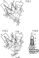
- FIGS 1 to 5 are partial and simplified views of a load cut-off device, such as a circuit breaker, these figures essentially showing the parts concerned by the present invention, while the control members and the housing do not are not shown.
- the device comprises an insulating support 1 in the form of a circular sector, which carries a fixed contact 2.
- the support 1 is crossed by an axis 3, on which is mounted a pivoting movable contact 4, able to cooperate in a particular angular position with the fixed contact 2.
- the mobile contact 4 here has a stirrup configuration, with two opposite branches located on either side of the support 1.
- the fixed contact 2 is also possible in the manner of a plastic cone.
- a helical spring 8, mounted around the pivot axis 3, ensures the pressure of the two branches of the movable contact 4 on the fixed contact 2 and on the pads 5, 6 and 7.
- An electrical input conductor 9 is connected to the movable contact 4, while an electrical output conductor 10 is connected to the fixed contact 2.
- first electrical resistance with a positive temperature coefficient 11 Between this fixed contact 2 and the first fixed stud 5 is inserted a first electrical resistance with a positive temperature coefficient 11. Between the first fixed stud 5 and the second fixed stud 6 is inserted a second electrical resistance with positive temperature coefficient 12, of higher ohmic value. An ordinary electrical resistance 13 is inserted between the second fixed stud 6 and the third fixed stud 7.
- Figure 1 shows the cut-off device in the closed position or "engaged” position.
- the movable contact 4 is pressed against the fixed contact 2.
- the electric current thus flows directly, through the contacts 2 and 4, from the input conductor 9 to the output conductor 10, without passing through the resistors with a positive temperature coefficient 11 and 12 and the resistor 13 which are then kept outside the circuit traversed by this current.
- the movable contact 4 pivots passing successively from the fixed contact 2 to the first fixed pad 5, from the first pad 5 to the second pad 6, and from the second pad 6 to the third pad 7, before reaching the beyond this last pad 7.
- the first resistor with a positive temperature coefficient 11 is temporarily inserted in the circuit traversed by the electric current between the input conductor 9 and the output conductor 10. If the current is initially of high intensity, the resistance with positive temperature coefficient 11 heats up quickly, and its ohmic value increases suddenly, which contributes to considerably limit the intensity of this current. On the other hand, the first resistor with a positive temperature coefficient 11 does not see its value suddenly increased, if it is traversed by a current of relatively low intensity.
- the second resistance with a positive temperature coefficient 12 does not intervene.
- this second resistance with positive temperature coefficient 12 sees its ohmic value increase suddenly, if the first resistance with positive temperature coefficient 11 has not intervened previously, therefore for a current of medium or low initial intensity; the intervention of the second resistor with a positive temperature coefficient 12 leads to lowering the intensity of this current to an even lower value.
- the movable contact 4 is wide enough to be able to be in momentary support on two successive pads, the next pad therefore being reached before this contact leaves the previous pad so that during the opening movement the values resistors 11, 12 and 13 can only be added.
- the operation of the device also requires that between each of the pairs of successive studs the voltage difference remains limited, and is for example below a maximum value of 20 volts.
- the movable contact 4 When closing, the movable contact 4 describes a reverse movement from the previous one, and it first reaches the third fixed stud 7, as shown in FIG. 5. In this position, the resistor 13 inserted in the circuit protects the second resistance with positive temperature coefficient 12, by limiting the intensity of the current to a value admissible by the latter.
- suitable means measure the intensity of the current thus limited, and control the continuation of the movement of the movable contact 4 towards the fixed contact 2 if the measured current is weak, or the return of the movable contact to the open position if the current measured is too strong.
- the two resistors with a positive temperature coefficient 11 and 12 therefore practically do not intervene during the closing movement described by the movable contact 4.
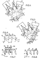
- FIG. 6 gives the electrical diagram corresponding to the embodiment described above, using the same numerical references.
- FIG. 7 illustrates, in the form of an electrical diagram, a first variant which comprises, between the fixed contact 4 and the first two fixed pads 5 and 6, a combination of resistors with positive temperature coefficients 11a, 11b, 12a, 12b in series , and varistors (resistors varying as a function of the electrical voltage) 14a, 14b, 15a, 15b in series; these provide voltage protection for resistors with a positive temperature coefficient, with respect to which they are connected in parallel.
- a resistor 13 is always inserted between the last two fixed studs 6 and 7. This variant allows the use of the cut-off device at a voltage greater than the admissible voltage by a single resistor with a positive temperature coefficient.
- FIG. 8 shows another variant, in which a first ordinary resistor 16 is inserted between the fixed contact 2 and the first fixed stud 5, a second ordinary resistor 17 is inserted between the first stud fixed 5 and the second fixed stud 6, and a resistance with a positive temperature coefficient 18 is inserted between the second fixed stud 6 and the third and last fixed stud 7.
- This arrangement makes it possible, first of all during cutting, to lower the intensity of the current, by the resistor 16 then by the resistor 17 added to the previous one, so as to bring this intensity to an admissible value by the resistor with positive temperature coefficient 18.
- it is important that 'between the consecutive pads the voltage is kept below a maximum value, for example 20 volts, during the opening process.
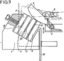
- FIGS. 1 to 5 show resistors in the form of components separated from the fixed contact 2 and from the fixed pads 5, 6 and 7, and connected to the latter by conductors such as that indicated in 19;
- FIG. 9 illustrates a different embodiment, in which the resistors with a positive temperature coefficient 11 and 12, and the resistor 13, are in the form of strips inserted directly between the fixed contact 2 and the pads 5, 6 and 7
- the operating principle is not modified by this configuration and it always requires that, in its movement, the movable contact 4 reach the next pad before having completely left the previous pad.
- the resistors with a positive temperature coefficient can be in particular made of polymer or ceramic.
Landscapes
- Arc-Extinguishing Devices That Are Switches (AREA)
Applications Claiming Priority (2)
| Application Number | Priority Date | Filing Date | Title |
|---|---|---|---|
| FR9107194A FR2677485A1 (fr) | 1991-06-07 | 1991-06-07 | Appareil de coupure en charge pour circuit electrique. |
| FR9107194 | 1991-06-07 |
Publications (2)
| Publication Number | Publication Date |
|---|---|
| EP0517618A1 true EP0517618A1 (de) | 1992-12-09 |
| EP0517618B1 EP0517618B1 (de) | 1995-04-12 |
Family
ID=9413776
Family Applications (1)
| Application Number | Title | Priority Date | Filing Date |
|---|---|---|---|
| EP92420154A Expired - Lifetime EP0517618B1 (de) | 1991-06-07 | 1992-05-12 | Lasttrenngerät für elektrische Schaltung |
Country Status (4)
| Country | Link |
|---|---|
| US (1) | US5193041A (de) |
| EP (1) | EP0517618B1 (de) |
| DE (1) | DE69202002T2 (de) |
| FR (1) | FR2677485A1 (de) |
Cited By (8)
| Publication number | Priority date | Publication date | Assignee | Title |
|---|---|---|---|---|
| DE4340632A1 (de) * | 1993-11-30 | 1995-06-01 | Abb Patent Gmbh | Elektrische Schalteinrichtung |
| US6659783B2 (en) | 2001-08-01 | 2003-12-09 | Tyco Electronics Corp | Electrical connector including variable resistance to reduce arcing |
| FR2944911A1 (fr) * | 2009-04-23 | 2010-10-29 | Areva T & D Sa | Interrupteur-sectionneur electrique rotatif de moyenne et haute tension a resistance |
| EP2450926A1 (de) * | 2010-11-08 | 2012-05-09 | ABB France | Elektrische Trennungsvorrichtung und damit versehener Überspannungsableiter |
| EP2600372A1 (de) * | 2011-11-30 | 2013-06-05 | General Electric Company | Elektrischer Schalter und Schutzschalter |
| EP2599760A1 (de) * | 2011-11-30 | 2013-06-05 | General Electric Company | Keramik, Monolith mit abgestuftem Widerstand mit der Keramik und Herstellungsverfahren |
| US9111670B2 (en) | 2011-11-30 | 2015-08-18 | General Electric Company | Ceramic, graded resistivity monolith using the ceramic, and method of making |
| EP4160637A1 (de) | 2021-10-01 | 2023-04-05 | Schneider Electric Industries SAS | Trennen von hochspannungsschaltkreisen |
Families Citing this family (4)
| Publication number | Priority date | Publication date | Assignee | Title |
|---|---|---|---|---|
| FR2883658B1 (fr) * | 2005-03-22 | 2009-04-24 | Schneider Electric Ind Sas | Dispositif de commutation d'un circuit electrique a ouverture sequentielle |
| US8890019B2 (en) | 2011-02-05 | 2014-11-18 | Roger Webster Faulkner | Commutating circuit breaker |
| CN104115250B (zh) * | 2011-09-30 | 2017-11-03 | 阿雷沃国际公司 | 换流断路器 |
| CN105723489B (zh) * | 2013-08-05 | 2019-06-04 | 英诺锂资产公司 | 具有阻断半导体的换向开关 |
Citations (4)
| Publication number | Priority date | Publication date | Assignee | Title |
|---|---|---|---|---|
| US2443230A (en) * | 1944-10-13 | 1948-06-15 | Coursey William E De | Nonarcing switch contact |
| GB1214682A (en) * | 1967-02-28 | 1970-12-02 | Mitsubishi Electric Corp | Circuits comprising current limiting devices |
| FR2409593A1 (fr) * | 1977-11-18 | 1979-06-15 | Bbc Brown Boveri & Cie | Interrupteur automatique de protection avec declencheur electromagnetique |
| US4583146A (en) * | 1984-10-29 | 1986-04-15 | General Electric Company | Fault current interrupter |
Family Cites Families (4)
| Publication number | Priority date | Publication date | Assignee | Title |
|---|---|---|---|---|
| US2071447A (en) * | 1934-03-24 | 1937-02-23 | Hugh E Young | Circuit breaker |
| US4093896A (en) * | 1976-08-11 | 1978-06-06 | Outboard Marine Corporation | Speed control for rotatable element driven by direct current motors |
| FR2581790B1 (fr) * | 1985-05-13 | 1988-12-30 | Stopcircuit Sa | Interrupteur disjoncteur a coupure propre |
| JPH01501431A (ja) * | 1986-11-28 | 1989-05-18 | ブディコ,ビクトル アレクサンドロビチ | 電気回路におけるアーク放電のないスイッチング装置 |
-
1991
- 1991-06-07 FR FR9107194A patent/FR2677485A1/fr active Granted
-
1992
- 1992-05-12 EP EP92420154A patent/EP0517618B1/de not_active Expired - Lifetime
- 1992-05-12 DE DE69202002T patent/DE69202002T2/de not_active Expired - Fee Related
- 1992-06-04 US US07/894,844 patent/US5193041A/en not_active Expired - Lifetime
Patent Citations (4)
| Publication number | Priority date | Publication date | Assignee | Title |
|---|---|---|---|---|
| US2443230A (en) * | 1944-10-13 | 1948-06-15 | Coursey William E De | Nonarcing switch contact |
| GB1214682A (en) * | 1967-02-28 | 1970-12-02 | Mitsubishi Electric Corp | Circuits comprising current limiting devices |
| FR2409593A1 (fr) * | 1977-11-18 | 1979-06-15 | Bbc Brown Boveri & Cie | Interrupteur automatique de protection avec declencheur electromagnetique |
| US4583146A (en) * | 1984-10-29 | 1986-04-15 | General Electric Company | Fault current interrupter |
Cited By (11)
| Publication number | Priority date | Publication date | Assignee | Title |
|---|---|---|---|---|
| DE4340632A1 (de) * | 1993-11-30 | 1995-06-01 | Abb Patent Gmbh | Elektrische Schalteinrichtung |
| US6659783B2 (en) | 2001-08-01 | 2003-12-09 | Tyco Electronics Corp | Electrical connector including variable resistance to reduce arcing |
| FR2944911A1 (fr) * | 2009-04-23 | 2010-10-29 | Areva T & D Sa | Interrupteur-sectionneur electrique rotatif de moyenne et haute tension a resistance |
| EP2450926A1 (de) * | 2010-11-08 | 2012-05-09 | ABB France | Elektrische Trennungsvorrichtung und damit versehener Überspannungsableiter |
| FR2967293A1 (fr) * | 2010-11-08 | 2012-05-11 | Abb France | Dispositif de deconnexion electrique et parafoudre comprenant un tel dispositif |
| EP2600372A1 (de) * | 2011-11-30 | 2013-06-05 | General Electric Company | Elektrischer Schalter und Schutzschalter |
| EP2599760A1 (de) * | 2011-11-30 | 2013-06-05 | General Electric Company | Keramik, Monolith mit abgestuftem Widerstand mit der Keramik und Herstellungsverfahren |
| US8773235B2 (en) | 2011-11-30 | 2014-07-08 | General Electric Company | Electrical switch and circuit breaker |
| US9111670B2 (en) | 2011-11-30 | 2015-08-18 | General Electric Company | Ceramic, graded resistivity monolith using the ceramic, and method of making |
| EP4160637A1 (de) | 2021-10-01 | 2023-04-05 | Schneider Electric Industries SAS | Trennen von hochspannungsschaltkreisen |
| US12170179B2 (en) | 2021-10-01 | 2024-12-17 | Schneider Electric Industries Sas | High-voltage circuit disconnection |
Also Published As
| Publication number | Publication date |
|---|---|
| US5193041A (en) | 1993-03-09 |
| DE69202002D1 (de) | 1995-05-18 |
| EP0517618B1 (de) | 1995-04-12 |
| FR2677485A1 (fr) | 1992-12-11 |
| FR2677485B1 (de) | 1994-04-22 |
| DE69202002T2 (de) | 1995-08-24 |
Similar Documents
| Publication | Publication Date | Title |
|---|---|---|
| EP0517618B1 (de) | Lasttrenngerät für elektrische Schaltung | |
| FR2606929A1 (fr) | Dispositif interrupteur pour appareil de protection | |
| EP0977233A1 (de) | Leistungsschalter mit hoher elektrodynamischer Festigkeit und Ausschaltleistung | |
| FR2714520A1 (fr) | Appareil électrique interrupteur à contacts séparables. | |
| CA2409260A1 (fr) | Systeme de protection d'un transformateur de distribution polyphase a isolation dans un dielectrique liquide, comportant au moins un interrupteur sectionneur de phase | |
| EP0461629B1 (de) | Leistungsschalter mit eingebautem Varistor | |
| CA2068857C (fr) | Disjoncteur a grand pouvoir de coupure | |
| EP1901320A1 (de) | Kontaktvorrichtung für ein Elektrogerät und Elektrogerät mit derartiger Vorrichtung | |
| EP3699942B1 (de) | Einschaltsystem einer vakuumschaltröhre | |
| EP1953788B1 (de) | Vorrichtung zum Schutz gegen Überspannungen mit beweglicher Elektrode und Entriegelungssystem der Verbindungsunterbrechungsvorrichtung | |
| EP1054419A1 (de) | Hochspannungstrennschalter mit schnellbeweglichem Kontakt | |
| FR2682219A1 (fr) | Disjoncteur ultra haute tension. | |
| FR2581790A1 (fr) | Interrupteur disjoncteur a coupure propre | |
| EP3157033B1 (de) | Trennkammer für ein elektrisches sicherungsgerät, und diese umfassendes elektrisches sicherungsgerät | |
| FR2506067A1 (fr) | Disjoncteur a haute tension | |
| EP1282146A1 (de) | Lichtbogenlöschvorrichtung | |
| EP2743958B1 (de) | Elektrisches Stromschaltgerät, insbesondere Abzweigschalter | |
| EP4485496B1 (de) | Elektrische schutzvorrichtung | |
| EP2619783B1 (de) | Schutzschalter mit einer vorrichtung für den einsatz eines resistors in eine stromleitung | |
| FR2827077A1 (fr) | Fusible a coupure integrale comportant un element polymere limiteur de courant chauffant une liaison thermofusible | |
| EP0532394A1 (de) | Schaltvorrichtung ohne natürlichen Nulldurchgang des Stromes | |
| FR2595867A1 (fr) | Interrupteur de circuit a limitation du courant | |
| FR3049760B1 (fr) | Appareil electrique de type disjoncteur | |
| FR2694444A1 (fr) | Perfectionnements aux dispositifs de coupure de ligne électrique. | |
| BE495058A (de) |
Legal Events
| Date | Code | Title | Description |
|---|---|---|---|
| PUAI | Public reference made under article 153(3) epc to a published international application that has entered the european phase |
Free format text: ORIGINAL CODE: 0009012 |
|
| AK | Designated contracting states |
Kind code of ref document: A1 Designated state(s): CH DE GB IT LI |
|
| 17P | Request for examination filed |
Effective date: 19921022 |
|
| 17Q | First examination report despatched |
Effective date: 19940914 |
|
| GRAA | (expected) grant |
Free format text: ORIGINAL CODE: 0009210 |
|
| AK | Designated contracting states |
Kind code of ref document: B1 Designated state(s): CH DE GB IT LI |
|
| ITF | It: translation for a ep patent filed | ||
| REF | Corresponds to: |
Ref document number: 69202002 Country of ref document: DE Date of ref document: 19950518 |
|
| GBT | Gb: translation of ep patent filed (gb section 77(6)(a)/1977) |
Effective date: 19950619 |
|
| PLBE | No opposition filed within time limit |
Free format text: ORIGINAL CODE: 0009261 |
|
| 26N | No opposition filed | ||
| REG | Reference to a national code |
Ref country code: GB Ref legal event code: IF02 |
|
| REG | Reference to a national code |
Ref country code: GB Ref legal event code: 732E |
|
| PGFP | Annual fee paid to national office [announced via postgrant information from national office to epo] |
Ref country code: DE Payment date: 20080514 Year of fee payment: 17 Ref country code: CH Payment date: 20080403 Year of fee payment: 17 |
|
| PGFP | Annual fee paid to national office [announced via postgrant information from national office to epo] |
Ref country code: IT Payment date: 20080520 Year of fee payment: 17 |
|
| PGFP | Annual fee paid to national office [announced via postgrant information from national office to epo] |
Ref country code: GB Payment date: 20080506 Year of fee payment: 17 |
|
| REG | Reference to a national code |
Ref country code: CH Ref legal event code: PL |
|
| GBPC | Gb: european patent ceased through non-payment of renewal fee |
Effective date: 20090512 |
|
| PG25 | Lapsed in a contracting state [announced via postgrant information from national office to epo] |
Ref country code: LI Free format text: LAPSE BECAUSE OF NON-PAYMENT OF DUE FEES Effective date: 20090531 Ref country code: CH Free format text: LAPSE BECAUSE OF NON-PAYMENT OF DUE FEES Effective date: 20090531 |
|
| PG25 | Lapsed in a contracting state [announced via postgrant information from national office to epo] |
Ref country code: GB Free format text: LAPSE BECAUSE OF NON-PAYMENT OF DUE FEES Effective date: 20090512 |
|
| PG25 | Lapsed in a contracting state [announced via postgrant information from national office to epo] |
Ref country code: DE Free format text: LAPSE BECAUSE OF NON-PAYMENT OF DUE FEES Effective date: 20091201 |
|
| PG25 | Lapsed in a contracting state [announced via postgrant information from national office to epo] |
Ref country code: IT Free format text: LAPSE BECAUSE OF NON-PAYMENT OF DUE FEES Effective date: 20090512 |