EP0517618A1 - Load-break device for electric circuit - Google Patents
Load-break device for electric circuit Download PDFInfo
- Publication number
- EP0517618A1 EP0517618A1 EP92420154A EP92420154A EP0517618A1 EP 0517618 A1 EP0517618 A1 EP 0517618A1 EP 92420154 A EP92420154 A EP 92420154A EP 92420154 A EP92420154 A EP 92420154A EP 0517618 A1 EP0517618 A1 EP 0517618A1
- Authority
- EP
- European Patent Office
- Prior art keywords
- movable contact
- temperature coefficient
- positive temperature
- circuit
- cut
- Prior art date
- Legal status (The legal status is an assumption and is not a legal conclusion. Google has not performed a legal analysis and makes no representation as to the accuracy of the status listed.)
- Granted
Links
Images
Classifications
-
- H—ELECTRICITY
- H01—ELECTRIC ELEMENTS
- H01H—ELECTRIC SWITCHES; RELAYS; SELECTORS; EMERGENCY PROTECTIVE DEVICES
- H01H9/00—Details of switching devices, not covered by groups H01H1/00 - H01H7/00
- H01H9/30—Means for extinguishing or preventing arc between current-carrying parts
- H01H9/42—Impedances connected with contacts
-
- H—ELECTRICITY
- H01—ELECTRIC ELEMENTS
- H01H—ELECTRIC SWITCHES; RELAYS; SELECTORS; EMERGENCY PROTECTIVE DEVICES
- H01H33/00—High-tension or heavy-current switches with arc-extinguishing or arc-preventing means
- H01H33/02—Details
- H01H33/04—Means for extinguishing or preventing arc between current-carrying parts
- H01H33/16—Impedances connected with contacts
- H01H33/161—Variable impedances
- H01H2033/163—Variable impedances using PTC elements
Definitions
- the present invention relates to a load cut-off device for an electrical circuit, this device possibly being in particular a switch-circuit breaker, but the field of the invention also includes contactors, switches, circuit breakers, relays and other similar devices. More particularly, this invention relates to a cut-off device under load called “cut-off without arc” or “clean cut-off", that is to say an apparatus provided with provisions which eliminate the risk of arcing between its contacts, when the relevant electrical circuit is cut under high current.
- French patent 8507804/2581790 in the name of the Applicant, describes a switch-circuit breaker with clean cut, of a particular structure.
- This switch-circuit breaker is of the type comprising a fixed contact, a movable contact, latching and tripping control members, means for hooking the movable contact carrier and the control member in the latched position, and means for actuating, in the direction of detachment, the means for hooking the mobile contact holder and the control member and neutralizing it, the mobile contact and the control member being subjected to the action of spring means tending to keep them in the tripped position.
- an auxiliary resistive circuit is provided arranged between the fixed and movable contacts, so as to interpose between them, when the movable contact is moved in the opening direction, an electrical resistance of value growing.
- This resistance makes it possible to reach, just before the total opening of the contacts, a current intensity sufficiently low to attenuate the risk of arcing; conversely, when the switch closes, the auxiliary resistance circuit introduces a resistance of decreasing value, also advantageous.
- This auxiliary resistive circuit is associated with the fixed contact, and it is arranged on the path of the mobile contact, or of an auxiliary contact associated with the mobile contact, to serve as a sliding track.
- the auxiliary resistive circuit is presented as a graphite or charged ceramic or doped polymer track, along which the movable contact or the auxiliary contact slides, the variable useful length (between the fixed contact and the movable or auxiliary contact ) of this track defining the value of the resistance inserted.
- the movable contact or the auxiliary contact has entirely left this track.
- the value of the resistance inserted during opening or closing varies according to purely "mechanical” criteria, depending on the movement of the movable contact in the direction of opening or closing , and it is practically not influenced by physical factors such as the intensity of the current or the temperature.
- the present invention aims to improve the kind of embodiment mentioned in the first place, so as to further improve the conditions under which the intensity of the current is lowered during the opening of the switch-circuit breaker or other similar breaking device, without altering the structure and functioning of the circuit under normal conditions.
- the subject of the invention is essentially a cut-off device under load for an electrical circuit, of the type known as "cut-off without arc” or “clean cut-off", comprising a fixed contact, a movable contact with which means are associated.
- the device for opening / closing control, and an auxiliary resistive circuit arranged so as to interpose between the fixed contact and the movable contact, when the latter is moved in the opening direction, an electrical resistance of increasing value
- the auxiliary resistive circuit comprises at least one resistance with a positive temperature coefficient capable of being temporarily inserted into the circuit traversed by the electric current during the opening movement of the movable contact, the resistance or resistors with coefficient of positive temperature being maintained outside the circuit traversed by this electric current, when the breaking device is in the closed position.
- the invention is based on the principle of insertion between the contact fixed and the movable contact, during the opening movement of the latter, of at least one resistance with a positive temperature coefficient, also known by the abbreviated designation "PTC", which is an electrical resistance whose ohmic value is a strongly increasing function of temperature.
- PTC positive temperature coefficient
- the passage of a current of high intensity in this resistance causes its immediate heating and consequently a sudden increase of its ohmic value, from where an acceleration of the lowering of this intensity, the current being very quickly reduced to a residual current of a few amperes, and the effect being all the more noticeable the higher the initial current.
- the resistance or resistors with a positive temperature coefficient are kept outside the circuit and are not stressed by any electric current and voltage, which preserves them and offers extended possibilities of circuit operation, in voltage and running.
- the auxiliary resistive circuit comprises at least two resistors with a positive temperature coefficient, arranged so as to be inserted successively between the fixed contact and the movable contact when the latter is moved in the direction of the opening.
- the resistors with a positive temperature coefficient are of increasing values, considered in their order of insertion between the fixed contact and the movable contact during the opening movement.
- the first resistance with positive temperature coefficient inserted intervenes to lower the strongest currents and limit them to a residual current
- the second resistance with positive temperature coefficient in series with the first (which did not intervene ) once inserted, intervenes to lower the medium or low currents and also limit them to a residual current.
- Two or more resistors with a positive temperature coefficient can, according to this principle, be successively inserted in series in the circuit between the fixed contact and the movable contact.
- the auxiliary resistive circuit can also comprise at least one ordinary electrical resistance, which during the opening movement of the movable contact is inserted in series with the resistance or resistors with positive temperature coefficient.
- the ordinary electrical resistance (s) are arranged so as to be inserted between the fixed contact and the movable contact, during the opening movement, after the resistance (s) with positive temperature coefficient, therefore at the end opening; in this case, the ordinary resistance has no particular function during opening, but it intervenes on closing to protect the resistance or resistors with a positive temperature coefficient, by limiting the intensity of the current to an admissible value. .
- the ordinary electrical resistance (s) are arranged so as to be inserted between the fixed contact and the movable contact, during the opening movement, before the resistance (s) with positive temperature coefficient, therefore at the start of opening, which makes it possible to lower the intensity of the current to an admissible value by the resistance or resistances with positive temperature coefficient.
- the auxiliary resistance circuit also comprises at least one varistor, mounted in parallel with respect to at least one resistance with positive temperature coefficient.
- the load breaking device advantageously comprises an insulating support which carries the fixed contact and several fixed conductive pads, all placed on the path of the movable contact, the resistors with a positive temperature coefficient and the ordinary resistance (s), if any, being inserted between the fixed contact and the first fixed stud and / or between the pairs of successive fixed studs, the movable contact being able to cooperate simultaneously with two successive studs during its opening or closing movement.
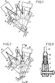
- FIGS 1 to 5 are partial and simplified views of a load cut-off device, such as a circuit breaker, these figures essentially showing the parts concerned by the present invention, while the control members and the housing do not are not shown.
- the device comprises an insulating support 1 in the form of a circular sector, which carries a fixed contact 2.
- the support 1 is crossed by an axis 3, on which is mounted a pivoting movable contact 4, able to cooperate in a particular angular position with the fixed contact 2.
- the mobile contact 4 here has a stirrup configuration, with two opposite branches located on either side of the support 1.
- the fixed contact 2 is also possible in the manner of a plastic cone.
- a helical spring 8, mounted around the pivot axis 3, ensures the pressure of the two branches of the movable contact 4 on the fixed contact 2 and on the pads 5, 6 and 7.
- An electrical input conductor 9 is connected to the movable contact 4, while an electrical output conductor 10 is connected to the fixed contact 2.
- first electrical resistance with a positive temperature coefficient 11 Between this fixed contact 2 and the first fixed stud 5 is inserted a first electrical resistance with a positive temperature coefficient 11. Between the first fixed stud 5 and the second fixed stud 6 is inserted a second electrical resistance with positive temperature coefficient 12, of higher ohmic value. An ordinary electrical resistance 13 is inserted between the second fixed stud 6 and the third fixed stud 7.
- Figure 1 shows the cut-off device in the closed position or "engaged” position.
- the movable contact 4 is pressed against the fixed contact 2.
- the electric current thus flows directly, through the contacts 2 and 4, from the input conductor 9 to the output conductor 10, without passing through the resistors with a positive temperature coefficient 11 and 12 and the resistor 13 which are then kept outside the circuit traversed by this current.
- the movable contact 4 pivots passing successively from the fixed contact 2 to the first fixed pad 5, from the first pad 5 to the second pad 6, and from the second pad 6 to the third pad 7, before reaching the beyond this last pad 7.
- the first resistor with a positive temperature coefficient 11 is temporarily inserted in the circuit traversed by the electric current between the input conductor 9 and the output conductor 10. If the current is initially of high intensity, the resistance with positive temperature coefficient 11 heats up quickly, and its ohmic value increases suddenly, which contributes to considerably limit the intensity of this current. On the other hand, the first resistor with a positive temperature coefficient 11 does not see its value suddenly increased, if it is traversed by a current of relatively low intensity.
- the second resistance with a positive temperature coefficient 12 does not intervene.
- this second resistance with positive temperature coefficient 12 sees its ohmic value increase suddenly, if the first resistance with positive temperature coefficient 11 has not intervened previously, therefore for a current of medium or low initial intensity; the intervention of the second resistor with a positive temperature coefficient 12 leads to lowering the intensity of this current to an even lower value.
- the movable contact 4 is wide enough to be able to be in momentary support on two successive pads, the next pad therefore being reached before this contact leaves the previous pad so that during the opening movement the values resistors 11, 12 and 13 can only be added.
- the operation of the device also requires that between each of the pairs of successive studs the voltage difference remains limited, and is for example below a maximum value of 20 volts.
- the movable contact 4 When closing, the movable contact 4 describes a reverse movement from the previous one, and it first reaches the third fixed stud 7, as shown in FIG. 5. In this position, the resistor 13 inserted in the circuit protects the second resistance with positive temperature coefficient 12, by limiting the intensity of the current to a value admissible by the latter.
- suitable means measure the intensity of the current thus limited, and control the continuation of the movement of the movable contact 4 towards the fixed contact 2 if the measured current is weak, or the return of the movable contact to the open position if the current measured is too strong.
- the two resistors with a positive temperature coefficient 11 and 12 therefore practically do not intervene during the closing movement described by the movable contact 4.
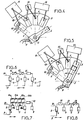
- FIG. 6 gives the electrical diagram corresponding to the embodiment described above, using the same numerical references.
- FIG. 7 illustrates, in the form of an electrical diagram, a first variant which comprises, between the fixed contact 4 and the first two fixed pads 5 and 6, a combination of resistors with positive temperature coefficients 11a, 11b, 12a, 12b in series , and varistors (resistors varying as a function of the electrical voltage) 14a, 14b, 15a, 15b in series; these provide voltage protection for resistors with a positive temperature coefficient, with respect to which they are connected in parallel.
- a resistor 13 is always inserted between the last two fixed studs 6 and 7. This variant allows the use of the cut-off device at a voltage greater than the admissible voltage by a single resistor with a positive temperature coefficient.
- FIG. 8 shows another variant, in which a first ordinary resistor 16 is inserted between the fixed contact 2 and the first fixed stud 5, a second ordinary resistor 17 is inserted between the first stud fixed 5 and the second fixed stud 6, and a resistance with a positive temperature coefficient 18 is inserted between the second fixed stud 6 and the third and last fixed stud 7.
- This arrangement makes it possible, first of all during cutting, to lower the intensity of the current, by the resistor 16 then by the resistor 17 added to the previous one, so as to bring this intensity to an admissible value by the resistor with positive temperature coefficient 18.
- it is important that 'between the consecutive pads the voltage is kept below a maximum value, for example 20 volts, during the opening process.
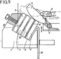
- FIGS. 1 to 5 show resistors in the form of components separated from the fixed contact 2 and from the fixed pads 5, 6 and 7, and connected to the latter by conductors such as that indicated in 19;
- FIG. 9 illustrates a different embodiment, in which the resistors with a positive temperature coefficient 11 and 12, and the resistor 13, are in the form of strips inserted directly between the fixed contact 2 and the pads 5, 6 and 7
- the operating principle is not modified by this configuration and it always requires that, in its movement, the movable contact 4 reach the next pad before having completely left the previous pad.
- the resistors with a positive temperature coefficient can be in particular made of polymer or ceramic.
Landscapes
- Arc-Extinguishing Devices That Are Switches (AREA)
Abstract
Description
La présente invention concerne un appareil de coupure en charge pour circuit électrique, cet appareil pouvant être notamment un interrupteur-disjoncteur, mais le domaine de l'invention englobant aussi les contacteurs, les interrupteurs, les disjoncteurs, les relais et autres appareillages similaires. Plus particulièrement, cette invention se rapporte à un appareil de coupure en charge dit "à coupure sans arc" ou "à coupure propre", c'est-à-dire un appareil pourvu de dispositions qui éliminent le risque de formation d'un arc électrique, entre ses contacts, lors de la coupure du circuit électrique concerné sous une forte intensité.The present invention relates to a load cut-off device for an electrical circuit, this device possibly being in particular a switch-circuit breaker, but the field of the invention also includes contactors, switches, circuit breakers, relays and other similar devices. More particularly, this invention relates to a cut-off device under load called "cut-off without arc" or "clean cut-off", that is to say an apparatus provided with provisions which eliminate the risk of arcing between its contacts, when the relevant electrical circuit is cut under high current.
Le brevet français 8507804/2581790, au nom de la Demanderesse, décrit un interrupteur-disjoncteur à coupure propre, d'une structure particulière. Cet interrupteur-disjoncteur est du type comportant un contact fixe, un contact mobile, des organes de commande d'enclenchement et de déclenchement, des moyens d'accrochage du porte-contact mobile et de l'organe de commande en position enclenchée, et des moyens pour actionner, dans le sens du décrochage, les moyens d'accrochage du porte-contact mobile et de l'organe de commande et le neutraliser, le contact mobile et l'organe de commande étant soumis à l'action de moyens à ressort tendant à les maintenir en position déclenchée. Selon l'invention objet de ce brevet, il est prévu un circuit résistant auxiliaire disposé entre les contacts fixe et mobile, de manière à interposer entre eux, lorsque le contact mobile est déplacé dans le sens de l'ouverture, une résistance électrique de valeur croissante. L'insertion de cette résistance permet d'atteindre, juste avant l'ouverture totale des contacts, une intensité de courant suffisamment faible pour atténuer le risque de formation d'arc ; inversement, lors de la fermeture de l'interrupteur, le circuit résistant auxiliaire introduit une résistance de valeur décroissante, également avantageuse. Ce circuit résistant auxiliaire est associé au contact fixe, et il est disposé sur le trajet du contact mobile, ou d'un contact auxiliaire associé au contact mobile, pour lui servir de piste de glissement. Ainsi, le circuit résistant auxiliaire se présente comme une piste en graphite ou en céramique chargée ou en polymère dopé, le long de laquelle glisse le contact mobile ou le contact auxiliaire, la longueur utile variable (entre le contact fixe et le contact mobile ou auxiliaire) de cette piste définissant la valeur de la résistance insérée. Bien entendu, en position de coupure, donc en fin de course d'ouverture, le contact mobile ou le contact auxiliaire a quitté entièrement cette piste.French patent 8507804/2581790, in the name of the Applicant, describes a switch-circuit breaker with clean cut, of a particular structure. This switch-circuit breaker is of the type comprising a fixed contact, a movable contact, latching and tripping control members, means for hooking the movable contact carrier and the control member in the latched position, and means for actuating, in the direction of detachment, the means for hooking the mobile contact holder and the control member and neutralizing it, the mobile contact and the control member being subjected to the action of spring means tending to keep them in the tripped position. According to the invention which is the subject of this patent, an auxiliary resistive circuit is provided arranged between the fixed and movable contacts, so as to interpose between them, when the movable contact is moved in the opening direction, an electrical resistance of value growing. The insertion of this resistance makes it possible to reach, just before the total opening of the contacts, a current intensity sufficiently low to attenuate the risk of arcing; conversely, when the switch closes, the auxiliary resistance circuit introduces a resistance of decreasing value, also advantageous. This auxiliary resistive circuit is associated with the fixed contact, and it is arranged on the path of the mobile contact, or of an auxiliary contact associated with the mobile contact, to serve as a sliding track. Thus, the auxiliary resistive circuit is presented as a graphite or charged ceramic or doped polymer track, along which the movable contact or the auxiliary contact slides, the variable useful length (between the fixed contact and the movable or auxiliary contact ) of this track defining the value of the resistance inserted. Of course, in the cut-off position, therefore at the end of the opening stroke, the movable contact or the auxiliary contact has entirely left this track.
Dans la réalisation évoquée ci-dessus, la valeur de la résistance insérée lors de l'ouverture ou de la fermeture varie selon des critères purement "mécaniques", en fonction du déplacement du contact mobile dans le sens de l'ouverture ou de la fermeture, et elle n'est pratiquement pas influencée par des facteurs physiques tels que l'intensité du courant ou la température.In the embodiment mentioned above, the value of the resistance inserted during opening or closing varies according to purely "mechanical" criteria, depending on the movement of the movable contact in the direction of opening or closing , and it is practically not influenced by physical factors such as the intensity of the current or the temperature.
Par ailleurs, on a déjà envisagé, dans des dispositifs de coupure en charge, l'utilisation d'éléments limiteurs de courant dont la résistance augmente avec l'accroissement de leur température, donc de l'intensité du courant qui les traverse. Toutefois, les éléments limiteurs ne font pas partie d'un circuit résistant auxiliaire de valeur croissante "mécaniquement" au cours du déplacement d'un contact mobile. De plus, ces éléments sont maintenus en permanence dans le circuit normalement parcouru par le courant électrique ; ainsi ils sont sollicités en permanence par un courant et une tension électriques, ce qui peut conduire à leur détérioration et limite les possibilités de fonctionnement du circuit, en tension et en courant. A ce sujet, il peut être fait référence au brevet britannique 1214682 et à son équivalent US 3529210, ou encore au brevet US 4583146.Furthermore, it has already been envisaged, in load cut-off devices, the use of current limiting elements whose resistance increases with the increase in their temperature, therefore in the intensity of the current flowing through them. However, the limiting elements are not part of an auxiliary resistive circuit of increasing value "mechanically" during the displacement of a movable contact. In addition, these elements are permanently maintained in the circuit normally traversed by the electric current; thus they are permanently requested by an electric current and a voltage, which can lead to their deterioration and limits the possibilities of operation of the circuit, in voltage and in current. In this regard, reference may be made to British patent 1214682 and its equivalent US 3529210, or to US patent 4583146.
La présente invention vise à perfectionner le genre de réalisation évoqué en premier lieu, de manière à améliorer encore les conditions dans lesquelles l'intensité du courant est abaissée au cours de l'ouverture de l'interrupteur-disjoncteur ou autre appareil de coupure similaire, sans que la structure et le fonctionnement du circuit en régime normal ne soient altérés.The present invention aims to improve the kind of embodiment mentioned in the first place, so as to further improve the conditions under which the intensity of the current is lowered during the opening of the switch-circuit breaker or other similar breaking device, without altering the structure and functioning of the circuit under normal conditions.
A cet effet, l'invention a essentiellement pour objet un appareil de coupure en charge pour circuit électrique, du genre dit "à coupure sans arc" ou "à coupure propre", comportant un contact fixe, un contact mobile auquel sont associés des moyens de commande d'ouverture/fermeture, et un circuit résistant auxiliaire disposé de manière à interposer entre le contact fixe et le contact mobile, lorsque ce dernier est déplacé dans le sens de l'ouverture, une résistance électrique de valeur croissante, l'appareil étant caractérisé en ce que le circuit résistant auxiliaire comprend au moins une résistance à coefficient de température positif apte à être insérée temporairement dans le circuit parcouru par le courant électrique au cours du mouvement d'ouverture du contact mobile, la ou les résistances à coefficient de température positif étant maintenues hors du circuit parcouru par ce courant électrique, lorsque l'appareil de coupure est en position de fermeture.To this end, the subject of the invention is essentially a cut-off device under load for an electrical circuit, of the type known as "cut-off without arc" or "clean cut-off", comprising a fixed contact, a movable contact with which means are associated. for opening / closing control, and an auxiliary resistive circuit arranged so as to interpose between the fixed contact and the movable contact, when the latter is moved in the opening direction, an electrical resistance of increasing value, the device being characterized in that the auxiliary resistive circuit comprises at least one resistance with a positive temperature coefficient capable of being temporarily inserted into the circuit traversed by the electric current during the opening movement of the movable contact, the resistance or resistors with coefficient of positive temperature being maintained outside the circuit traversed by this electric current, when the breaking device is in the closed position.
Ainsi, l'invention repose sur le principe de l'insertion entre le contact fixe et le contact mobile, au cours du mouvement d'ouverture de ce dernier, d'au moins une résistance à coefficient de température positif, connue aussi sous la désignation abrégée "CTP", qui est une résistance électrique dont la valeur ohmique est une fonction fortement croissante de la température. Ainsi, le passage d'un courant de forte intensité dans cette résistance provoque son échauffement immédiat et par conséquent une augmentation brusque de sa valeur ohmique, d'où une accélération de l'abaissement de cette intensité, le courant se trouvant très rapidement réduit à un courant résiduel de quelques ampères, et l'effet étant d'autant plus sensible que le courant initial était élevé. Par contre, en régime permanent, la ou les résistances à coefficient de température positif sont maintenues hors du circuit et ne sont sollicitées par aucun courant et par aucune tension électriques, ce qui les préserve et offre des possibilités étendues de fonctionnement du circuit, en tension et en courant.Thus, the invention is based on the principle of insertion between the contact fixed and the movable contact, during the opening movement of the latter, of at least one resistance with a positive temperature coefficient, also known by the abbreviated designation "PTC", which is an electrical resistance whose ohmic value is a strongly increasing function of temperature. Thus, the passage of a current of high intensity in this resistance causes its immediate heating and consequently a sudden increase of its ohmic value, from where an acceleration of the lowering of this intensity, the current being very quickly reduced to a residual current of a few amperes, and the effect being all the more noticeable the higher the initial current. On the other hand, in steady state, the resistance or resistors with a positive temperature coefficient are kept outside the circuit and are not stressed by any electric current and voltage, which preserves them and offers extended possibilities of circuit operation, in voltage and running.
Selon une forme de réalisation préférée de l'invention, le circuit résistant auxiliaire comprend au moins deux résistances à coefficient de température positif, disposées de manière à être insérées successivement entre le contact fixe et le contact mobile lorsque ce dernier est déplacé dans le sens de l'ouverture. Avantageusement, les résistances à coefficient de température positif sont de valeurs croissantes, considérées dans leur ordre d'insertion entre le contact fixe et le contact mobile au cours du mouvement d'ouverture. Ainsi, la première résistance à coefficient de température positif insérée intervient pour abaisser les courants les plus forts et les limiter à un courant résiduel, tandis que la deuxième résistance à coefficient de température positif, en série avec la première (qui n'est pas intervenue) une fois insérée, intervient pour abaisser les courants moyens ou faibles et les limiter aussi à un courant résiduel. Deux ou plusieurs résistances à coefficient de température positif peuvent, selon ce principe, être successivement insérées en série dans le circuit entre le contact fixe et le contact mobile.According to a preferred embodiment of the invention, the auxiliary resistive circuit comprises at least two resistors with a positive temperature coefficient, arranged so as to be inserted successively between the fixed contact and the movable contact when the latter is moved in the direction of the opening. Advantageously, the resistors with a positive temperature coefficient are of increasing values, considered in their order of insertion between the fixed contact and the movable contact during the opening movement. Thus, the first resistance with positive temperature coefficient inserted intervenes to lower the strongest currents and limit them to a residual current, while the second resistance with positive temperature coefficient, in series with the first (which did not intervene ) once inserted, intervenes to lower the medium or low currents and also limit them to a residual current. Two or more resistors with a positive temperature coefficient can, according to this principle, be successively inserted in series in the circuit between the fixed contact and the movable contact.
Le circuit résistant auxiliaire peut comprendre encore au moins une résistance électrique ordinaire, qui au cours du mouvement d'ouverture du contact mobile est insérée en série avec la ou les résistances à coefficient de température positif. Selon une première possibilité, la ou les résistances électriques ordinaires sont disposées de manière à être insérées entre le contact fixe et le contact mobile, au cours du mouvement d'ouverture, après la ou les résistances à coefficient de température positif, donc en fin d'ouverture ; dans ce cas, la résistance ordinaire n'a pas de fonction particulière lors de l'ouverture, mais elle intervient à la fermeture pour protéger la ou les résistances à coefficient de température positif, en y limitant l'intensité du courant à une valeur admissible. Selon une autre possibilité, la ou les résistances électriques ordinaires sont disposées de manière à être insérées entre le contact fixe et le contact mobile, au cours du mouvement d'ouverture, avant la ou les résistances à coefficient de température positif, donc en début d'ouverture, ce qui permet d'abaisser l'intensité du courant à une valeur admissible par la ou les résistances à coefficient de température positif.The auxiliary resistive circuit can also comprise at least one ordinary electrical resistance, which during the opening movement of the movable contact is inserted in series with the resistance or resistors with positive temperature coefficient. According to a first possibility, the ordinary electrical resistance (s) are arranged so as to be inserted between the fixed contact and the movable contact, during the opening movement, after the resistance (s) with positive temperature coefficient, therefore at the end opening; in this case, the ordinary resistance has no particular function during opening, but it intervenes on closing to protect the resistance or resistors with a positive temperature coefficient, by limiting the intensity of the current to an admissible value. . According to another possibility, the ordinary electrical resistance (s) are arranged so as to be inserted between the fixed contact and the movable contact, during the opening movement, before the resistance (s) with positive temperature coefficient, therefore at the start of opening, which makes it possible to lower the intensity of the current to an admissible value by the resistance or resistances with positive temperature coefficient.
Selon une autre disposition visant à la protection de la ou des résistances à coefficient de température positif, le circuit résistant auxiliaire comprend encore au moins une varistance, montée en parallèle par rapport à au moins une résistance à coefficient de température positif.According to another arrangement aimed at protecting the resistance or resistors with a positive temperature coefficient, the auxiliary resistance circuit also comprises at least one varistor, mounted in parallel with respect to at least one resistance with positive temperature coefficient.
Pour la réalisation pratique du circuit résistant auxiliaire, l'appareil de coupure en charge selon l'invention comprend, avantageusement, un support isolant qui porte le contact fixe et plusieurs plots conducteurs fixes, tous placés sur la trajectoire du contact mobile, la ou les résistances à coefficient de température positif et la ou les éventuelles résistances ordinaires étant insérées entre le contact fixe et le premier plot fixe et/ou entre les paires de plots fixes successifs, le contact mobile étant apte à coopérer simultanément avec deux plots successifs au cours de son mouvement d'ouverture ou de fermeture.For the practical realization of the auxiliary resistive circuit, the load breaking device according to the invention advantageously comprises an insulating support which carries the fixed contact and several fixed conductive pads, all placed on the path of the movable contact, the resistors with a positive temperature coefficient and the ordinary resistance (s), if any, being inserted between the fixed contact and the first fixed stud and / or between the pairs of successive fixed studs, the movable contact being able to cooperate simultaneously with two successive studs during its opening or closing movement.
De toute façon, l'invention sera mieux comprise à l'aide de la description qui suit, en référence au dessin schématique annexé représentant, à titre d'exemples non limitatifs, quelques formes d'exécution de cet appareil de coupure en charge pour circuit électrique :
- Figure 1 est une vue de face simplifiée d'un appareil de coupure conforme à la présente invention, en position de fermeture du circuit électrique ;
- Figure 2 est une vue similaire à la figure 1, mais montrant l'appareil en cours d'ouverture ;
- Figure 3 est une vue en coupe de cet appareil de coupure, suivant III-III de figure 2 ;
- Figure 4 est une vue de face simplifiée du même appareil, en position d'ouverture du circuit ;
- Figure 5 est une vue similaire à la précédente, montrant l'appareil en cours de fermeture ;
- Figure 6 est un schéma électrique correspondant à l'appareil des figures 1 à 5 ;
- Figures 7 et 8 sont des schémas électriques illustrant deux variantes de cet appareil ;
- Figure 9 est une vue partielle d'une autre variante.
- Figure 1 is a simplified front view of a switching device according to the present invention, in the closed position of the electrical circuit;
- Figure 2 is a view similar to Figure 1, but showing the apparatus being opened;
- Figure 3 is a sectional view of this switching device, along III-III of Figure 2;
- Figure 4 is a simplified front view of the same device, in the open position of the circuit;
- Figure 5 is a view similar to the previous one, showing the apparatus in closing price;
- Figure 6 is an electrical diagram corresponding to the apparatus of Figures 1 to 5;
- Figures 7 and 8 are electrical diagrams illustrating two variants of this device;
- Figure 9 is a partial view of another variant.
Les figures 1 à 5 sont des vues partielles et simplifiées d'un appareil de coupure en charge, tel qu'un interrupteur-disjoncteur, ces figures montrant essentiellement les parties concernées par la présente invention, tandis que les organes de commande et le boîtier ne sont pas représentés.Figures 1 to 5 are partial and simplified views of a load cut-off device, such as a circuit breaker, these figures essentially showing the parts concerned by the present invention, while the control members and the housing do not are not shown.
L'appareil comprend un support isolant 1 en forme de secteur circulaire, qui porte un contact fixe 2. Le support 1 est traversé par un axe 3, sur lequel est monté un contact mobile pivotant 4, apte à coopérer dans une position angulaire particulière avec le contact fixe 2. Comme le montre la figure 3, le contact mobile 4 présente ici une configuration en étrier, avec deux branches opposées situées de part et d'autre du support 1.The device comprises an insulating support 1 in the form of a circular sector, which carries a
Sur le support isolant 1 sont encore disposés plusieurs plots conducteurs fixes 5,6 et 7, tous placés sur la trajectoire en arc de cercle décrite par l'extrémité du contact mobile pivotant 4. Le contact fixe 2 est également réalisable à la manière d'un plot. Un ressort hélicoïdal 8, monté autour de l'axe de pivotement 3, assure la pression des deux branches du contact mobile 4 sur le contact fixe 2 et sur les plots 5,6 et 7.On the insulating support 1 are also arranged several fixed
Un conducteur électrique d'entrée 9 est raccordé au contact mobile 4, tandis qu'un conducteur électrique de sortie 10 est raccordé au contact fixe 2.An
Entre ce contact fixe 2 et le premier plot fixe 5 est insérée une première résistance électrique à coefficient de température positif 11. Entre le premier plot fixe 5 et le deuxième plot fixe 6 est insérée une seconde résistance électrique à coefficient de température positif 12, de valeur ohmique plus élevée. Une résistance électrique ordinaire 13 est insérée entre le deuxième plot fixe 6 et le troisième plot fixe 7.Between this
La figure 1 montre l'appareil de coupure en position de fermeture ou position "enclenchée". Le contact mobile 4 se trouve appuyé contre le contact fixe 2. Le courant électrique chemine ainsi directement, par les contacts 2 et 4, du conducteur d'entrée 9 vers le conducteur de sortie 10, sans parcourir les résistances à coefficient de température positif 11 et 12 et la résistance 13 qui sont alors maintenues hors du circuit parcouru par ce courant.Figure 1 shows the cut-off device in the closed position or "engaged" position. The
Au cours du mouvement d'ouverture, le contact mobile 4 pivote en passant successivement du contact fixe 2 au premier plot fixe 5, du premier plot 5 au deuxième plot 6, et du deuxième plot 6 au troisième plot 7, avant de parvenir au-delà de ce dernier plot 7.During the opening movement, the
En début d'ouverture, quand le contact mobile 4 est passé sur le premier plot fixe 5, la première résistance à coefficient de température positif 11 se trouve insérée temporairement dans le circuit parcouru par le courant électrique entre le conducteur d'entrée 9 et le conducteur de sortie 10. Si le courant est initialement de forte intensité, la résistance à coefficient de température positif 11 s'échauffe rapidement, et sa valeur ohmique augmente brusquement, ce qui contribue à limiter considérablement l'intensité de ce courant. Par contre, la première résistance à coefficient de température positif 11 ne voit pas sa valeur brusquement augmentée, si elle est parcourue par un courant d'intensité relativement faible.At the start of opening, when the
Le mouvement d'ouverture se poursuivant, le contact mobile 4 passe ensuite du premier plot fixe 5 au deuxième plot fixe 6, comme illustré aux figures 2 et 3. La seconde résistance à coefficient de température positif 12 est ainsi insérée dans le circuit, en série avec la première résistance à coefficient de température positif 11.The opening movement continuing, the
Si précédemment la première résistance à coefficient de température positif 11 est intervenue, pour atténuer un courant d'intensité initiale élevée, la seconde résistance à coefficient de température positif 12 n'intervient pas. Par contre, cette seconde résistance à coefficient de température positif 12 voit sa valeur ohmique augmenter brusquement, si la première résistance à coefficient de température positif 11 n'est pas intervenue précédemment, donc pour un courant d'intensité initiale moyenne ou faible ; l'intervention de la seconde résistance à coefficient de température positif 12 conduit à abaisser l'intensité de ce courant vers une valeur encore plus faible.If previously the first resistance with a
Le mouvement d'ouverture continuant de s'effectuer, le contact mobile 4 passe sur le troisième plot fixe 7, puis il poursuit sa course au-delà de ce dernier plot 7 et atteint finalement la position d'ouverture ou position "déclenchée", montrée sur la figure 4, dans laquelle le passage du courant entre le conducteur d'entrée 9 et le conducteur de sortie 10 est totalement empêché. Il est à noter qu'au cours de ce mouvement d'ouverture, la résistance 13 se trouve temporairement insérée dans le circuit mais n'a alors aucune fonction particulière.The opening movement continuing to take place, the
On notera aussi que le contact mobile 4 est suffisamment large pour pouvoir être en appui momentané sur deux plots successifs, le plot suivant étant donc atteint avant que ce contact ne quitte le plot précédent de sorte qu'au cours du mouvement d'ouverture les valeurs des résistances 11,12 et 13 ne peuvent que s'ajouter. Le fonctionnement du dispositif impose en outre qu'entre chacune des paires de plots successifs la différence de tension reste limitée, et se situe par exemple en dessous d'une valeur maximum de 20 volts.It will also be noted that the
Lors de la fermeture, le contact mobile 4 décrit un mouvement inverse du précédent, et il parvient d'abord sur le troisième plot fixe 7, comme représenté sur la figure 5. Dans cette position, la résistance 13 insérée dans le circuit protège la seconde résistance à coefficient de température positif 12, en limitant l'intensité du courant à une valeur admissible par cette dernière.When closing, the
De préférence, à l'instant où le contact mobile 4 atteint le plot fixe 7, des moyens appropriés mesurent l'intensité du courant ainsi limité, et commandent la poursuite du mouvement du contact mobile 4 vers le contact fixe 2 si le courant mesuré est faible, ou le retour du contact mobile en position ouverte si le courant mesuré est trop fort. Les deux résistances à coefficient de température positif 11 et 12 n'interviennent donc pratiquement pas lors du mouvement de fermeture décrit par le contact mobile 4.Preferably, at the instant when the
La figure 6 donne le schéma électrique correspondant à la réalisation précédemment décrite, avec utilisation des mêmes repères numériques.FIG. 6 gives the electrical diagram corresponding to the embodiment described above, using the same numerical references.
La figure 7 illustre, sous forme de schéma électrique, une première variante qui comporte, entre le contact fixe 4 et les deux premiers plots fixes 5 et 6, une association de résistances à coefficients de température positif 11a, 11b, 12a, 12b en série, et de varistances (résistances variables en fonction de la tension électrique) 14a, 14b, 15a, 15b en série ; ces dernières assurent la protection en tension des résistances à coefficient de température positif, par rapport auxquelles elles sont montées en parallèle. Une résistance 13 est toujours insérée entre les deux derniers plots fixes 6 et 7. Cette variante permet l'utilisation de l'appareil de coupure sous une tension supérieure à la tension admissible par une seule résistance à coefficient de température positif.FIG. 7 illustrates, in the form of an electrical diagram, a first variant which comprises, between the
La figure 8 montre une autre variante, dans laquelle une première résistance ordinaire 16 est insérée entre le contact fixe 2 et le premier plot fixe 5, une seconde résistance ordinaire 17 est insérée entre le premier plot fixe 5 et le deuxième plot fixe 6, et une résistance à coefficient de température positif 18 est insérée entre le deuxième plot fixe 6 et le troisième et dernier plot fixe 7. Cette disposition permet, lors de la coupure, d'abaisser d'abord l'intensité du courant, par la résistance 16 puis par la résistance 17 s'ajoutant à la précédente, de façon à ramener cette intensité à une valeur admissible par la résistance à coefficient de température positif 18. Dans ce cas également, il importe qu'entre les plots consécutifs la tension soit maintenue au-dessous d'une valeur maximum, par exemple de 20 volts, pendant le processus d'ouverture.FIG. 8 shows another variant, in which a first
Les figures 1 à 5 montrent des résistances sous forme de composants séparés du contact fixe 2 et des plots fixes 5,6 et 7, et reliés à ces derniers par des conducteurs tels que celui indiqué en 19 ; la figure 9 illustre un mode de réalisation différent, dans lequel les résistances à coefficient de température positif 11 et 12, et la résistance 13, se présentent sous la forme de lamelles insérées directement entre le contact fixe 2 et les plots 5,6 et 7. Le principe de fonctionnement n'est pas modifié par cette configuration et il exige toujours que, dans son mouvement, le contact mobile 4 atteigne le plot suivant avant d'avoir entièrement quitté le plot précédent.FIGS. 1 to 5 show resistors in the form of components separated from the fixed
Les résistances à coefficient de température positif, ici utilisées, peuvent être notamment en polymère ou en céramique.The resistors with a positive temperature coefficient, used here, can be in particular made of polymer or ceramic.
Comme il va de soi, l'invention ne se limite pas aux seules formes d'exécution de cet appareil de coupure en charge pour circuit électrique qui ont été décrites ci-dessus, à titre d'exemples ; elle en embrasse, au contraire, toutes les variantes de réalisation et d'application respectant le même principe. C'est ainsi, notamment, que l'on ne s'éloignerait pas du cadre de l'invention :
- en augmentant le nombre des plots intermédiaires et des résistances à coefficient de température positif, insérées successivement dans le circuit au cours du mouvement d'ouverture, ces résistances étant de valeurs ohmiques croissantes ;
- en prévoyant des associations de résistances à coefficient de température positif de mêmes caractéristiques, branchées en parallèle, pour augmenter la valeur maximale de l'intensité du courant pouvant être coupé ;
- en modifiant la disposition des plots fixes et le mouvement du contact mobile, comme le suggère d'ailleurs la figure 9, ce mouvement pouvant être un glissement et/ou un roulement ;
- en prévoyant un trajet différent du contact mobile, pour le mouvement de fermeture, de manière à ne pas insérer les résistances à coefficient de température positif lors du rétablissement du courant ;
- en appliquant l'invention à des appareils de coupure en charge autres que des interrupteurs-disjoncteurs, tels que des contacteurs, des interrupteurs, des disjoncteurs, des relais et autres appareillages similaires.
- by increasing the number of intermediate pads and resistors with a positive temperature coefficient, successively inserted into the circuit during the opening movement, these resistors being of increasing ohmic values;
- by providing associations of resistors with a positive temperature coefficient of the same characteristics, connected in parallel, to increase the maximum value of the intensity of the current which can be cut;
- by modifying the arrangement of the fixed pads and the movement of the movable contact, as moreover suggests in FIG. 9, this movement possibly being a sliding and / or a rolling;
- by planning a different route from the mobile contact, for the closing movement, so as not to insert resistors with a positive temperature coefficient when power is restored;
- by applying the invention to load breaking devices other than switch-circuit breakers, such as contactors, switches, circuit breakers, relays and other similar equipment.
Claims (10)
Applications Claiming Priority (2)
| Application Number | Priority Date | Filing Date | Title |
|---|---|---|---|
| FR9107194A FR2677485A1 (en) | 1991-06-07 | 1991-06-07 | LOAD CUTTING APPARATUS FOR ELECTRICAL CIRCUIT. |
| FR9107194 | 1991-06-07 |
Publications (2)
| Publication Number | Publication Date |
|---|---|
| EP0517618A1 true EP0517618A1 (en) | 1992-12-09 |
| EP0517618B1 EP0517618B1 (en) | 1995-04-12 |
Family
ID=9413776
Family Applications (1)
| Application Number | Title | Priority Date | Filing Date |
|---|---|---|---|
| EP92420154A Expired - Lifetime EP0517618B1 (en) | 1991-06-07 | 1992-05-12 | Load-break device for electric circuit |
Country Status (4)
| Country | Link |
|---|---|
| US (1) | US5193041A (en) |
| EP (1) | EP0517618B1 (en) |
| DE (1) | DE69202002T2 (en) |
| FR (1) | FR2677485A1 (en) |
Cited By (8)
| Publication number | Priority date | Publication date | Assignee | Title |
|---|---|---|---|---|
| DE4340632A1 (en) * | 1993-11-30 | 1995-06-01 | Abb Patent Gmbh | Electrical switching device |
| US6659783B2 (en) | 2001-08-01 | 2003-12-09 | Tyco Electronics Corp | Electrical connector including variable resistance to reduce arcing |
| FR2944911A1 (en) * | 2009-04-23 | 2010-10-29 | Areva T & D Sa | Electric switch-disconnector for use in lines of medium and high voltage electric energy transmission, has fixing contact fixed in displacement direction by resistor, where value of resistor changes according to position of mobile contact |
| EP2450926A1 (en) * | 2010-11-08 | 2012-05-09 | ABB France | Electrical disconnection device and surge arrester having the same |
| EP2600372A1 (en) * | 2011-11-30 | 2013-06-05 | General Electric Company | Electrical switch and circuit breaker |
| EP2599760A1 (en) * | 2011-11-30 | 2013-06-05 | General Electric Company | Ceramic, graded resistivity monolith using the ceramic, and method of making |
| US9111670B2 (en) | 2011-11-30 | 2015-08-18 | General Electric Company | Ceramic, graded resistivity monolith using the ceramic, and method of making |
| EP4160637A1 (en) | 2021-10-01 | 2023-04-05 | Schneider Electric Industries SAS | Disconnection for high-voltage circuits |
Families Citing this family (4)
| Publication number | Priority date | Publication date | Assignee | Title |
|---|---|---|---|---|
| FR2883658B1 (en) * | 2005-03-22 | 2009-04-24 | Schneider Electric Ind Sas | DEVICE FOR SWITCHING A SEQUENTIALLY OPENING ELECTRICAL CIRCUIT |
| US8890019B2 (en) | 2011-02-05 | 2014-11-18 | Roger Webster Faulkner | Commutating circuit breaker |
| CN104115250B (en) * | 2011-09-30 | 2017-11-03 | 阿雷沃国际公司 | Change of current breaker |
| CN105723489B (en) * | 2013-08-05 | 2019-06-04 | 英诺锂资产公司 | Reversing switch with blocking semiconductor |
Citations (4)
| Publication number | Priority date | Publication date | Assignee | Title |
|---|---|---|---|---|
| US2443230A (en) * | 1944-10-13 | 1948-06-15 | Coursey William E De | Nonarcing switch contact |
| GB1214682A (en) * | 1967-02-28 | 1970-12-02 | Mitsubishi Electric Corp | Circuits comprising current limiting devices |
| FR2409593A1 (en) * | 1977-11-18 | 1979-06-15 | Bbc Brown Boveri & Cie | Protective disconnector with electromagnetic release - has resistor in parallel with extra bimetal contacts in series with release coil |
| US4583146A (en) * | 1984-10-29 | 1986-04-15 | General Electric Company | Fault current interrupter |
Family Cites Families (4)
| Publication number | Priority date | Publication date | Assignee | Title |
|---|---|---|---|---|
| US2071447A (en) * | 1934-03-24 | 1937-02-23 | Hugh E Young | Circuit breaker |
| US4093896A (en) * | 1976-08-11 | 1978-06-06 | Outboard Marine Corporation | Speed control for rotatable element driven by direct current motors |
| FR2581790B1 (en) * | 1985-05-13 | 1988-12-30 | Stopcircuit Sa | CLEAN BREAKER CIRCUIT BREAKER |
| JPH01501431A (en) * | 1986-11-28 | 1989-05-18 | ブディコ,ビクトル アレクサンドロビチ | Arc-free switching devices in electrical circuits |
-
1991
- 1991-06-07 FR FR9107194A patent/FR2677485A1/en active Granted
-
1992
- 1992-05-12 EP EP92420154A patent/EP0517618B1/en not_active Expired - Lifetime
- 1992-05-12 DE DE69202002T patent/DE69202002T2/en not_active Expired - Fee Related
- 1992-06-04 US US07/894,844 patent/US5193041A/en not_active Expired - Lifetime
Patent Citations (4)
| Publication number | Priority date | Publication date | Assignee | Title |
|---|---|---|---|---|
| US2443230A (en) * | 1944-10-13 | 1948-06-15 | Coursey William E De | Nonarcing switch contact |
| GB1214682A (en) * | 1967-02-28 | 1970-12-02 | Mitsubishi Electric Corp | Circuits comprising current limiting devices |
| FR2409593A1 (en) * | 1977-11-18 | 1979-06-15 | Bbc Brown Boveri & Cie | Protective disconnector with electromagnetic release - has resistor in parallel with extra bimetal contacts in series with release coil |
| US4583146A (en) * | 1984-10-29 | 1986-04-15 | General Electric Company | Fault current interrupter |
Cited By (11)
| Publication number | Priority date | Publication date | Assignee | Title |
|---|---|---|---|---|
| DE4340632A1 (en) * | 1993-11-30 | 1995-06-01 | Abb Patent Gmbh | Electrical switching device |
| US6659783B2 (en) | 2001-08-01 | 2003-12-09 | Tyco Electronics Corp | Electrical connector including variable resistance to reduce arcing |
| FR2944911A1 (en) * | 2009-04-23 | 2010-10-29 | Areva T & D Sa | Electric switch-disconnector for use in lines of medium and high voltage electric energy transmission, has fixing contact fixed in displacement direction by resistor, where value of resistor changes according to position of mobile contact |
| EP2450926A1 (en) * | 2010-11-08 | 2012-05-09 | ABB France | Electrical disconnection device and surge arrester having the same |
| FR2967293A1 (en) * | 2010-11-08 | 2012-05-11 | Abb France | ELECTRICAL DISCONNECTING DEVICE AND PARAFOUDRE COMPRISING SUCH A DEVICE |
| EP2600372A1 (en) * | 2011-11-30 | 2013-06-05 | General Electric Company | Electrical switch and circuit breaker |
| EP2599760A1 (en) * | 2011-11-30 | 2013-06-05 | General Electric Company | Ceramic, graded resistivity monolith using the ceramic, and method of making |
| US8773235B2 (en) | 2011-11-30 | 2014-07-08 | General Electric Company | Electrical switch and circuit breaker |
| US9111670B2 (en) | 2011-11-30 | 2015-08-18 | General Electric Company | Ceramic, graded resistivity monolith using the ceramic, and method of making |
| EP4160637A1 (en) | 2021-10-01 | 2023-04-05 | Schneider Electric Industries SAS | Disconnection for high-voltage circuits |
| US12170179B2 (en) | 2021-10-01 | 2024-12-17 | Schneider Electric Industries Sas | High-voltage circuit disconnection |
Also Published As
| Publication number | Publication date |
|---|---|
| US5193041A (en) | 1993-03-09 |
| DE69202002D1 (en) | 1995-05-18 |
| EP0517618B1 (en) | 1995-04-12 |
| FR2677485A1 (en) | 1992-12-11 |
| FR2677485B1 (en) | 1994-04-22 |
| DE69202002T2 (en) | 1995-08-24 |
Similar Documents
| Publication | Publication Date | Title |
|---|---|---|
| EP0517618B1 (en) | Load-break device for electric circuit | |
| FR2606929A1 (en) | SWITCH DEVICE FOR PROTECTIVE APPARATUS | |
| EP0977233A1 (en) | Circuit breaker with high electrodynamic strength and breaking capacity | |
| FR2714520A1 (en) | Electrical switch with separable contacts. | |
| CA2409260A1 (en) | Protection system for a liquid dielectric polyphase distribution transformer having at least one phase disconnect switch | |
| EP0461629B1 (en) | Circuit breaker incorporating a varistor | |
| CA2068857C (en) | Circuit breaker with high breaking capacity | |
| EP1901320A1 (en) | Contact device for an electrical apparatus and electrical apparatus provided with such a device | |
| EP3699942B1 (en) | Operating system for a vacuum bulb | |
| EP1953788B1 (en) | Device for protecting against voltage surges with a mobile electrode with system for unlocking the disconnection device | |
| EP1054419A1 (en) | High tension isolating switch with a mobile contact movable at high speed | |
| FR2682219A1 (en) | ULTRA HIGH VOLTAGE CIRCUIT BREAKER. | |
| FR2581790A1 (en) | Clean-break circuit breaker switch. | |
| EP3157033B1 (en) | Arc extinguishing chamber of an electrical protection device and electrical protection device comprising such a chamber | |
| FR2506067A1 (en) | High voltage circuit breaker - where main switch has by=pass circuit contg. rows of resistors employed to quench arc when switch is opened | |
| EP1282146A1 (en) | Arc extinguishing device | |
| EP2743958B1 (en) | Electric current breaking apparatus, in particular a coupling breaker | |
| EP4485496B1 (en) | Electrical protection device | |
| EP2619783B1 (en) | Circuit breaker comprising a device for inserting a resistor into a power line | |
| FR2827077A1 (en) | Excess current electrical motor/transformer protection having fusible circuit breaker polymer current limiter fusible ring connected outer tubing and spring removing contact when fuse operates. | |
| EP0532394A1 (en) | Circuit breaker device without natural zero crossing for the current | |
| FR2595867A1 (en) | CIRCUIT SWITCH WITH CURRENT LIMITATION | |
| FR3049760B1 (en) | CIRCUIT BREAKER TYPE ELECTRICAL APPARATUS | |
| FR2694444A1 (en) | Circuit breaker for high voltage power line - has isolating switch with casing housing fix and mobile contacts and elastic screen while switch is connected in parallel with controlled atmosphere switch | |
| BE495058A (en) |
Legal Events
| Date | Code | Title | Description |
|---|---|---|---|
| PUAI | Public reference made under article 153(3) epc to a published international application that has entered the european phase |
Free format text: ORIGINAL CODE: 0009012 |
|
| AK | Designated contracting states |
Kind code of ref document: A1 Designated state(s): CH DE GB IT LI |
|
| 17P | Request for examination filed |
Effective date: 19921022 |
|
| 17Q | First examination report despatched |
Effective date: 19940914 |
|
| GRAA | (expected) grant |
Free format text: ORIGINAL CODE: 0009210 |
|
| AK | Designated contracting states |
Kind code of ref document: B1 Designated state(s): CH DE GB IT LI |
|
| ITF | It: translation for a ep patent filed | ||
| REF | Corresponds to: |
Ref document number: 69202002 Country of ref document: DE Date of ref document: 19950518 |
|
| GBT | Gb: translation of ep patent filed (gb section 77(6)(a)/1977) |
Effective date: 19950619 |
|
| PLBE | No opposition filed within time limit |
Free format text: ORIGINAL CODE: 0009261 |
|
| 26N | No opposition filed | ||
| REG | Reference to a national code |
Ref country code: GB Ref legal event code: IF02 |
|
| REG | Reference to a national code |
Ref country code: GB Ref legal event code: 732E |
|
| PGFP | Annual fee paid to national office [announced via postgrant information from national office to epo] |
Ref country code: DE Payment date: 20080514 Year of fee payment: 17 Ref country code: CH Payment date: 20080403 Year of fee payment: 17 |
|
| PGFP | Annual fee paid to national office [announced via postgrant information from national office to epo] |
Ref country code: IT Payment date: 20080520 Year of fee payment: 17 |
|
| PGFP | Annual fee paid to national office [announced via postgrant information from national office to epo] |
Ref country code: GB Payment date: 20080506 Year of fee payment: 17 |
|
| REG | Reference to a national code |
Ref country code: CH Ref legal event code: PL |
|
| GBPC | Gb: european patent ceased through non-payment of renewal fee |
Effective date: 20090512 |
|
| PG25 | Lapsed in a contracting state [announced via postgrant information from national office to epo] |
Ref country code: LI Free format text: LAPSE BECAUSE OF NON-PAYMENT OF DUE FEES Effective date: 20090531 Ref country code: CH Free format text: LAPSE BECAUSE OF NON-PAYMENT OF DUE FEES Effective date: 20090531 |
|
| PG25 | Lapsed in a contracting state [announced via postgrant information from national office to epo] |
Ref country code: GB Free format text: LAPSE BECAUSE OF NON-PAYMENT OF DUE FEES Effective date: 20090512 |
|
| PG25 | Lapsed in a contracting state [announced via postgrant information from national office to epo] |
Ref country code: DE Free format text: LAPSE BECAUSE OF NON-PAYMENT OF DUE FEES Effective date: 20091201 |
|
| PG25 | Lapsed in a contracting state [announced via postgrant information from national office to epo] |
Ref country code: IT Free format text: LAPSE BECAUSE OF NON-PAYMENT OF DUE FEES Effective date: 20090512 |