EP1282146A1 - Lichtbogenlöschvorrichtung - Google Patents
Lichtbogenlöschvorrichtung Download PDFInfo
- Publication number
- EP1282146A1 EP1282146A1 EP02291721A EP02291721A EP1282146A1 EP 1282146 A1 EP1282146 A1 EP 1282146A1 EP 02291721 A EP02291721 A EP 02291721A EP 02291721 A EP02291721 A EP 02291721A EP 1282146 A1 EP1282146 A1 EP 1282146A1
- Authority
- EP
- European Patent Office
- Prior art keywords
- contact
- conductive
- fixed contact
- arc
- conductive part
- Prior art date
- Legal status (The legal status is an assumption and is not a legal conclusion. Google has not performed a legal analysis and makes no representation as to the accuracy of the status listed.)
- Granted
Links
Images
Classifications
-
- H—ELECTRICITY
- H01—ELECTRIC ELEMENTS
- H01H—ELECTRIC SWITCHES; RELAYS; SELECTORS; EMERGENCY PROTECTIVE DEVICES
- H01H73/00—Protective overload circuit-breaking switches in which excess current opens the contacts by automatic release of mechanical energy stored by previous operation of a hand reset mechanism
- H01H73/02—Details
- H01H73/18—Means for extinguishing or suppressing arc
-
- H—ELECTRICITY
- H01—ELECTRIC ELEMENTS
- H01H—ELECTRIC SWITCHES; RELAYS; SELECTORS; EMERGENCY PROTECTIVE DEVICES
- H01H9/00—Details of switching devices, not covered by groups H01H1/00 - H01H7/00
- H01H9/30—Means for extinguishing or preventing arc between current-carrying parts
- H01H9/46—Means for extinguishing or preventing arc between current-carrying parts using arcing horns
Definitions
- the invention relates to a device for extinguishing an electric arc for a protective device such as a circuit breaker.
- the invention aims to improve a such device, in particular by increasing its breaking capacity.
- the first conductive part is produced in copper, the second conductive part being preferably made in a ferromagnetic material, for example steel, while the fixed contact is in particular in the form of a silver pellet. This results in a better conduction of the electric arc.
- the invention also proposes, according to a second aspect, a circuit breaker limiter comprising a device as previously described.
- this circuit breaker comprises an electromagnet adapted to control the separation of the fixed and mobile contacts, said electromagnet comprising an electrically connected coil at the end, on the one hand, a contact terminal of the circuit breaker and, secondly, to the first piece conductive.
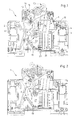
- FIGS. 1 and 2 show a limiter circuit breaker 1 comprising a housing 2 in which is housed a control device 3 opening a electrical circuit 4 connecting an input terminal 5 to an output terminal 6.
- the circuit breaker 1 has a fixed contact 7 electrically connected to the terminal input 5, and a movable contact 8 electrically connected to the output terminal 6.
- the movable contact 8 is here produced in the form of a metal lever pivoting; it is adapted to occupy, on the one hand, in a so-called configuration switched on circuit breaker 1, shown in Figure 1, a so-called closed position in which it comes to apply against the fixed contact 7 by establishing with it a electrical contact and, on the other hand, in a so-called triggered configuration of the circuit breaker 1, illustrated in FIG. 2, a so-called open position in which it is discarded from the fixed contact 7.
- the control device 3 comprises an electromagnet 9 consisting of a coil 10 electrically connected at the end on the one hand, to the input terminal 5 and on the other hand, at the fixed contact 7, and a ferromagnetic core 11 introduced into the spiral winding of the coil 10.
- the core 11 is mounted mobile in translation along the main axis of the winding of the coil 10, and it is adapted to move, under the effect of a overcurrent of the current flowing in the coil 10, from an inactive position to an active position in which, by pushing at one of its ends a trigger 12 which, in the engaged configuration, maintains the moving contact 8 in the closed position against a return spring 13, causes the moving the movable contact 8 to its open position to open the circuit electrical 4 and trip circuit breaker 1.
- a reset mechanism 14 comprising a lever 15 to provision of the user and whose displacement after triggering the circuit breaker 1, is able, through a set of levers 16, to restore contact mobile 8 in closed position.
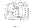
- the circuit breaker 1 further comprises a device 19 for extinguishing the arc 17, which has a breaking chamber 20 located at a distance from the zone 18 and formed of a plurality of conductive plates 21 superimposed, as well as two drivers facing each other commonly called horns, namely an upstream horn 22 and a downstream horn 23, these horns 22, 23 being adapted to guide the arc 17 from the training zone 18 to the chamber cutoff 20 where it is off.
- a breaking chamber 20 located at a distance from the zone 18 and formed of a plurality of conductive plates 21 superimposed, as well as two drivers facing each other commonly called horns, namely an upstream horn 22 and a downstream horn 23, these horns 22, 23 being adapted to guide the arc 17 from the training zone 18 to the chamber cutoff 20 where it is off.
- each horn 22, 23 has an anterior portion 24, 26 delimiting a space called prechamber 28, located between the zone of formation 18 of the arc 17 and the breaking chamber 20, each anterior portion 24, 26 being extended by a posterior portion 25, 27 which borders the chamber cutoff 20.
- the front portions 24, 26 horns 22, 23 are first convergent from the formation zone 18 of the arc 17 to an intermediate zone 29 located in the prechamber 28, then diverging from this intermediate zone 29 to the interrupting chamber 20.
- the upstream horn 22 is formed of two conductive parts distinct, namely a first piece 30 which forms the anterior portion 24 of the horn 22, and a second piece 31 which forms its posterior portion 25.
- These two conductive pieces 30, 31 overlap in the prechamber 28 at vicinity of the breaking chamber 20, in this case at the limit thereof, the second conductive part 31 being, in line with the point of overlap, shifted outward from the prechamber 28 relative to the first piece conductor 30.
- the point of overlap of the two conductive parts 30, 31 is in the part of the prechamber 28 where the horns 22, 23 diverge.
- the electric arc 17, which was propelled to the interior of the prechamber 28 towards the breaking chamber 20 reaches the point of overlap after passing intermediate zone 29 he jumps out of the first conductive part 30 to the second 31 without particular difficulty.
- the two conductive parts 30, 31 are in simple mechanical contact, no particular electrical connection such as a welding being provided between them.
- the second conductive part 31 is embedded in the first 30, this imbrication sufficient to maintain relative two parts conductive 30, 31 relative to each other.
- the first conductive part 30 is here in the form of a blade made of copper, or steel covered with a layer of copper, folded so as to have a C-shaped profile and arranged so that its concavity is oriented towards the interrupting chamber 20.
- the second conductive part 31 is also formed of a metal blade, preferably made of a material ferromagnetic, especially steel, and which has a straight portion 35 bordering the interrupting chamber 20, extended towards the first conductive part 30 by a bent portion 36 having a substantially complementary shape of the first conductive part 30 and nested in it, so that the second conductive part 31 has a substantially b-shaped profile whose curved part is turned towards the prechamber 28.
- the two conductive parts 30, 31 are, in fine, in contact mechanical in several places. However, it is preferable that they are in contact at least to the right of the fixed contact 7.
- This configuration namely the shape and the relative arrangement of the parts conductors 30, 31, in particular the arrangement of the first conductive part
- the material of the first and second conductive parts 30, 31, respectively copper and steel provides a magnetic effect which concentration of a magnetic field around the arc 17, propels the latter from the formation zone 18 to the interrupting chamber 20.
- the fixed contact 7 presents itself in the form of a silver pellet reported on the first conductive part 30, so that if the electrical conductivity of the upstream horn 22 goes into descending from the formation zone 18 of the arc 17 to the chamber of cut 20, its mechanical resistance to wear is increasing, which forms a good compromise between the guiding capabilities of the arc 17 and the durability of the extinguishing device 19.
- the latter carries a ramp 37 which substantially continuously connects the contact face 38 of the fixed contact 7, against which is able to come to apply the movable contact 8, and the surface 39 of the first conductive part 30.
- This ramp 37 presents the advantage of facilitating the positioning of the fixed contact 7 on the first piece conductor 30 during assembly.
- downstream horn 23 this can be carried out in a manner conventional copper, or preferably steel covered for example with a layer of copper so as to present both good electrical conductivity and mechanical resistance to wear under the effect of the arc.
Landscapes
- Arc-Extinguishing Devices That Are Switches (AREA)
Applications Claiming Priority (2)
| Application Number | Priority Date | Filing Date | Title |
|---|---|---|---|
| FR0110256 | 2001-07-31 | ||
| FR0110256A FR2828329B1 (fr) | 2001-07-31 | 2001-07-31 | Dispositif pour l'extinction d'un arc electrique |
Publications (2)
| Publication Number | Publication Date |
|---|---|
| EP1282146A1 true EP1282146A1 (de) | 2003-02-05 |
| EP1282146B1 EP1282146B1 (de) | 2008-12-17 |
Family
ID=8866130
Family Applications (1)
| Application Number | Title | Priority Date | Filing Date |
|---|---|---|---|
| EP20020291721 Expired - Lifetime EP1282146B1 (de) | 2001-07-31 | 2002-07-09 | Lichtbogenlöschvorrichtung |
Country Status (6)
| Country | Link |
|---|---|
| EP (1) | EP1282146B1 (de) |
| CN (1) | CN1238879C (de) |
| DE (1) | DE60230367D1 (de) |
| ES (1) | ES2319739T3 (de) |
| FR (1) | FR2828329B1 (de) |
| PL (1) | PL202507B1 (de) |
Cited By (3)
| Publication number | Priority date | Publication date | Assignee | Title |
|---|---|---|---|---|
| EP2256771A2 (de) * | 2009-05-30 | 2010-12-01 | Abb Ag | Elektrisches Schaltgerät mit einem thermischen Auslöser |
| EP3029706A1 (de) * | 2014-12-01 | 2016-06-08 | Hager-Electro SAS (Société par Actions Simplifiée) | Unterbrechungsvorrichtung und modularer fehlerstromschutzschalter, der mindestens eine solche unterbrechungsvorrichtung umfasst |
| EP3188211A1 (de) | 2015-12-29 | 2017-07-05 | Legrand France | Elektrische schutzvorrichtung für den leistungsschutz |
Families Citing this family (2)
| Publication number | Priority date | Publication date | Assignee | Title |
|---|---|---|---|---|
| JP4957072B2 (ja) * | 2006-05-11 | 2012-06-20 | 富士電機機器制御株式会社 | 回路遮断器 |
| CN105185671B (zh) * | 2015-10-30 | 2019-06-25 | 上海电科电器科技有限公司 | 断路器及其挡板 |
Citations (5)
| Publication number | Priority date | Publication date | Assignee | Title |
|---|---|---|---|---|
| DE1008383B (de) * | 1953-01-21 | 1957-05-16 | Siemens Ag | Schaltstueck |
| US4112275A (en) * | 1973-03-26 | 1978-09-05 | Siemens Aktiengesellschaft | Contact structure for electrical switching apparatus |
| DE2930090B1 (de) * | 1979-07-25 | 1981-01-08 | Licentia Gmbh | Leitungsschutzschalter mit einer Loeschbleche und Lichtbogenleitschienen aufweisenden Lichtbogenkammer |
| EP0080924A1 (de) * | 1981-11-27 | 1983-06-08 | Merlin Gerin | Kleinstschutzschalter mit zwei nebeneinander angeordneten Löschkammern |
| FR2604026A1 (fr) * | 1986-09-16 | 1988-03-18 | Mitsubishi Electric Corp | Disjoncteur possedant une structure perfectionnee d'extinction d'arc |
-
2001
- 2001-07-31 FR FR0110256A patent/FR2828329B1/fr not_active Expired - Fee Related
-
2002
- 2002-07-09 EP EP20020291721 patent/EP1282146B1/de not_active Expired - Lifetime
- 2002-07-09 ES ES02291721T patent/ES2319739T3/es not_active Expired - Lifetime
- 2002-07-09 DE DE60230367T patent/DE60230367D1/de not_active Expired - Lifetime
- 2002-07-23 PL PL355160A patent/PL202507B1/pl unknown
- 2002-07-31 CN CN 02127293 patent/CN1238879C/zh not_active Expired - Fee Related
Patent Citations (5)
| Publication number | Priority date | Publication date | Assignee | Title |
|---|---|---|---|---|
| DE1008383B (de) * | 1953-01-21 | 1957-05-16 | Siemens Ag | Schaltstueck |
| US4112275A (en) * | 1973-03-26 | 1978-09-05 | Siemens Aktiengesellschaft | Contact structure for electrical switching apparatus |
| DE2930090B1 (de) * | 1979-07-25 | 1981-01-08 | Licentia Gmbh | Leitungsschutzschalter mit einer Loeschbleche und Lichtbogenleitschienen aufweisenden Lichtbogenkammer |
| EP0080924A1 (de) * | 1981-11-27 | 1983-06-08 | Merlin Gerin | Kleinstschutzschalter mit zwei nebeneinander angeordneten Löschkammern |
| FR2604026A1 (fr) * | 1986-09-16 | 1988-03-18 | Mitsubishi Electric Corp | Disjoncteur possedant une structure perfectionnee d'extinction d'arc |
Cited By (5)
| Publication number | Priority date | Publication date | Assignee | Title |
|---|---|---|---|---|
| EP2256771A2 (de) * | 2009-05-30 | 2010-12-01 | Abb Ag | Elektrisches Schaltgerät mit einem thermischen Auslöser |
| EP2256771A3 (de) * | 2009-05-30 | 2014-06-18 | Abb Ag | Elektrisches Schaltgerät mit einem thermischen Auslöser |
| EP3029706A1 (de) * | 2014-12-01 | 2016-06-08 | Hager-Electro SAS (Société par Actions Simplifiée) | Unterbrechungsvorrichtung und modularer fehlerstromschutzschalter, der mindestens eine solche unterbrechungsvorrichtung umfasst |
| EP3188211A1 (de) | 2015-12-29 | 2017-07-05 | Legrand France | Elektrische schutzvorrichtung für den leistungsschutz |
| RU2719326C2 (ru) * | 2015-12-29 | 2020-04-17 | Легран Франс | Электрическое защитное устройство в модульном формате |
Also Published As
| Publication number | Publication date |
|---|---|
| CN1238879C (zh) | 2006-01-25 |
| PL202507B1 (pl) | 2009-06-30 |
| CN1405819A (zh) | 2003-03-26 |
| ES2319739T3 (es) | 2009-05-12 |
| FR2828329A1 (fr) | 2003-02-07 |
| EP1282146B1 (de) | 2008-12-17 |
| PL355160A1 (en) | 2003-02-10 |
| DE60230367D1 (de) | 2009-01-29 |
| FR2828329B1 (fr) | 2003-12-12 |
Similar Documents
| Publication | Publication Date | Title |
|---|---|---|
| EP1146529B1 (de) | Pol für einen strombegrenzenden Niederspannungsleistungsschalter und damit ausgestalteter Leistungsschalter | |
| FR2714520A1 (fr) | Appareil électrique interrupteur à contacts séparables. | |
| FR2578355A1 (fr) | Disjoncteur limiteur de courant | |
| EP1282146B1 (de) | Lichtbogenlöschvorrichtung | |
| EP0517618B1 (de) | Lasttrenngerät für elektrische Schaltung | |
| EP1764811B1 (de) | Trennschalter mit einer verkleineten Lichtbogenlöschkammer | |
| FR2777111A1 (fr) | Disjoncteur | |
| EP0003447B1 (de) | Vorrichtung zur Beschränkung und Unterbrechung des Stroms | |
| EP0635859B1 (de) | Lastschalter mit einem Bedienungsmechanismus welcher durch einen elektromagnetische Auslöser gesteuert wird | |
| EP0932176A1 (de) | Lichtbogenkammer für Selbstbeblasender Lastschalter mit rotierendem Lichtbogen | |
| FR2475290A1 (fr) | Chambre de coupure de disjoncteurs basse tension a joues composites de guidage de l'arc | |
| FR2788164A1 (fr) | Appareillage electrique de coupure dont un organe de contact est muni d'une fente | |
| EP0047696B1 (de) | Kleinstselbstschalter mit Lichtbogenkontakten | |
| EP1505619B1 (de) | Verbessertes Schlossmechanismus für Schutzschalter und Schutzschalter mit solchem Schloss | |
| FR2581790A1 (fr) | Interrupteur disjoncteur a coupure propre | |
| EP1065684B1 (de) | Elektrisches Schaltgerät mit einer Schutzfunktvorrichtung für einen Kontakt | |
| EP0403328A1 (de) | Elektrische Schaltapparate | |
| EP0926694B1 (de) | Magnetothermische Steuervorrichtung und mit einer solchen Vorrichtung ausgerüsteter Schutzschalter | |
| EP0045672B1 (de) | Kleinschalter mit Abschaltung des Nulleiters und des Phasenleiters | |
| EP1168402B1 (de) | Magnetische Baugruppe für ein elektrisches Gerät mit einer begrenzten Breite | |
| EP0004801A2 (de) | Schalter mit einer elektromagnetischen Einrichtung zur schnellen Öffnung des beweglichen Kontaktes | |
| EP0518786B1 (de) | Elektrischer Vakuumschalter | |
| EP3029706B1 (de) | Unterbrechungsvorrichtung und modularer fehlerstromschutzschalter, der mindestens eine solche unterbrechungsvorrichtung umfasst | |
| EP0649156B1 (de) | Schutzeinrichtung dargestellt durch die Reihenschaltung eines Schutzschalters mit einem Schaltgerät | |
| FR2806522A1 (fr) | Dispositif de declenchement magnetique notamment pour disjoncteur, et appareil de protection electrique comportant un tel dispositif |
Legal Events
| Date | Code | Title | Description |
|---|---|---|---|
| PUAI | Public reference made under article 153(3) epc to a published international application that has entered the european phase |
Free format text: ORIGINAL CODE: 0009012 |
|
| AK | Designated contracting states |
Designated state(s): AT BE BG CH CY CZ DE DK EE ES FI FR GB GR IE IT LI LU MC NL PT SE SK TR |
|
| AX | Request for extension of the european patent |
Extension state: AL LT LV MK RO SI |
|
| 17P | Request for examination filed |
Effective date: 20030313 |
|
| AKX | Designation fees paid |
Designated state(s): BE DE ES GB IT TR |
|
| RAP1 | Party data changed (applicant data changed or rights of an application transferred) |
Owner name: LEGRAND FRANCE Owner name: LEGRAND SNC |
|
| 17Q | First examination report despatched |
Effective date: 20070504 |
|
| GRAP | Despatch of communication of intention to grant a patent |
Free format text: ORIGINAL CODE: EPIDOSNIGR1 |
|
| GRAS | Grant fee paid |
Free format text: ORIGINAL CODE: EPIDOSNIGR3 |
|
| GRAA | (expected) grant |
Free format text: ORIGINAL CODE: 0009210 |
|
| AK | Designated contracting states |
Kind code of ref document: B1 Designated state(s): BE DE ES GB IT TR |
|
| REG | Reference to a national code |
Ref country code: GB Ref legal event code: FG4D Free format text: NOT ENGLISH |
|
| REF | Corresponds to: |
Ref document number: 60230367 Country of ref document: DE Date of ref document: 20090129 Kind code of ref document: P |
|
| REG | Reference to a national code |
Ref country code: ES Ref legal event code: FG2A Ref document number: 2319739 Country of ref document: ES Kind code of ref document: T3 |
|
| PLBE | No opposition filed within time limit |
Free format text: ORIGINAL CODE: 0009261 |
|
| STAA | Information on the status of an ep patent application or granted ep patent |
Free format text: STATUS: NO OPPOSITION FILED WITHIN TIME LIMIT |
|
| 26N | No opposition filed |
Effective date: 20090918 |
|
| BERE | Be: lapsed |
Owner name: LEGRAND FRANCE Effective date: 20090731 Owner name: LEGRAND SNC Effective date: 20090731 |
|
| GBPC | Gb: european patent ceased through non-payment of renewal fee |
Effective date: 20090709 |
|
| PG25 | Lapsed in a contracting state [announced via postgrant information from national office to epo] |
Ref country code: GB Free format text: LAPSE BECAUSE OF NON-PAYMENT OF DUE FEES Effective date: 20090709 |
|
| PG25 | Lapsed in a contracting state [announced via postgrant information from national office to epo] |
Ref country code: BE Free format text: LAPSE BECAUSE OF NON-PAYMENT OF DUE FEES Effective date: 20090731 |
|
| PGFP | Annual fee paid to national office [announced via postgrant information from national office to epo] |
Ref country code: TR Payment date: 20120614 Year of fee payment: 11 |
|
| PGFP | Annual fee paid to national office [announced via postgrant information from national office to epo] |
Ref country code: ES Payment date: 20120706 Year of fee payment: 11 |
|
| REG | Reference to a national code |
Ref country code: ES Ref legal event code: FD2A Effective date: 20140909 |
|
| PG25 | Lapsed in a contracting state [announced via postgrant information from national office to epo] |
Ref country code: ES Free format text: LAPSE BECAUSE OF NON-PAYMENT OF DUE FEES Effective date: 20130710 |
|
| PG25 | Lapsed in a contracting state [announced via postgrant information from national office to epo] |
Ref country code: TR Free format text: LAPSE BECAUSE OF NON-PAYMENT OF DUE FEES Effective date: 20130709 |
|
| PGFP | Annual fee paid to national office [announced via postgrant information from national office to epo] |
Ref country code: DE Payment date: 20150729 Year of fee payment: 14 |
|
| REG | Reference to a national code |
Ref country code: DE Ref legal event code: R119 Ref document number: 60230367 Country of ref document: DE |
|
| PG25 | Lapsed in a contracting state [announced via postgrant information from national office to epo] |
Ref country code: DE Free format text: LAPSE BECAUSE OF NON-PAYMENT OF DUE FEES Effective date: 20170201 |
|
| PGFP | Annual fee paid to national office [announced via postgrant information from national office to epo] |
Ref country code: IT Payment date: 20190718 Year of fee payment: 18 |
|
| PG25 | Lapsed in a contracting state [announced via postgrant information from national office to epo] |
Ref country code: IT Free format text: LAPSE BECAUSE OF NON-PAYMENT OF DUE FEES Effective date: 20200709 |