EP0515922A1 - Serrure à combinaison pour valise, meuble ou similaire - Google Patents
Serrure à combinaison pour valise, meuble ou similaire Download PDFInfo
- Publication number
- EP0515922A1 EP0515922A1 EP19920108211 EP92108211A EP0515922A1 EP 0515922 A1 EP0515922 A1 EP 0515922A1 EP 19920108211 EP19920108211 EP 19920108211 EP 92108211 A EP92108211 A EP 92108211A EP 0515922 A1 EP0515922 A1 EP 0515922A1
- Authority
- EP
- European Patent Office
- Prior art keywords
- permutation lock
- particular according
- locking
- permutation
- operating handle
- Prior art date
- Legal status (The legal status is an assumption and is not a legal conclusion. Google has not performed a legal analysis and makes no representation as to the accuracy of the status listed.)
- Granted
Links
Images


Classifications
-
- E—FIXED CONSTRUCTIONS
- E05—LOCKS; KEYS; WINDOW OR DOOR FITTINGS; SAFES
- E05B—LOCKS; ACCESSORIES THEREFOR; HANDCUFFS
- E05B37/00—Permutation or combination locks; Puzzle locks
- E05B37/02—Permutation or combination locks; Puzzle locks with tumbler discs or rings arranged on a single axis, each disc being adjustable independently of the others
-
- E—FIXED CONSTRUCTIONS
- E05—LOCKS; KEYS; WINDOW OR DOOR FITTINGS; SAFES
- E05B—LOCKS; ACCESSORIES THEREFOR; HANDCUFFS
- E05B37/00—Permutation or combination locks; Puzzle locks
- E05B37/0075—Automatic scrambling
-
- Y—GENERAL TAGGING OF NEW TECHNOLOGICAL DEVELOPMENTS; GENERAL TAGGING OF CROSS-SECTIONAL TECHNOLOGIES SPANNING OVER SEVERAL SECTIONS OF THE IPC; TECHNICAL SUBJECTS COVERED BY FORMER USPC CROSS-REFERENCE ART COLLECTIONS [XRACs] AND DIGESTS
- Y10—TECHNICAL SUBJECTS COVERED BY FORMER USPC
- Y10T—TECHNICAL SUBJECTS COVERED BY FORMER US CLASSIFICATION
- Y10T70/00—Locks
- Y10T70/70—Operating mechanism
- Y10T70/7153—Combination
- Y10T70/7181—Tumbler type
- Y10T70/7198—Single tumbler set
- Y10T70/7237—Rotary or swinging tumblers
- Y10T70/726—Individually set
- Y10T70/7305—Manually operable
-
- Y—GENERAL TAGGING OF NEW TECHNOLOGICAL DEVELOPMENTS; GENERAL TAGGING OF CROSS-SECTIONAL TECHNOLOGIES SPANNING OVER SEVERAL SECTIONS OF THE IPC; TECHNICAL SUBJECTS COVERED BY FORMER USPC CROSS-REFERENCE ART COLLECTIONS [XRACs] AND DIGESTS
- Y10—TECHNICAL SUBJECTS COVERED BY FORMER USPC
- Y10T—TECHNICAL SUBJECTS COVERED BY FORMER US CLASSIFICATION
- Y10T70/00—Locks
- Y10T70/70—Operating mechanism
- Y10T70/7153—Combination
- Y10T70/7316—Combination upsetting
-
- Y—GENERAL TAGGING OF NEW TECHNOLOGICAL DEVELOPMENTS; GENERAL TAGGING OF CROSS-SECTIONAL TECHNOLOGIES SPANNING OVER SEVERAL SECTIONS OF THE IPC; TECHNICAL SUBJECTS COVERED BY FORMER USPC CROSS-REFERENCE ART COLLECTIONS [XRACs] AND DIGESTS
- Y10—TECHNICAL SUBJECTS COVERED BY FORMER USPC
- Y10T—TECHNICAL SUBJECTS COVERED BY FORMER US CLASSIFICATION
- Y10T70/00—Locks
- Y10T70/70—Operating mechanism
- Y10T70/7153—Combination
- Y10T70/735—Operating elements
- Y10T70/7356—Fences
- Y10T70/7362—Bolt or lock housing supported
Definitions
- the invention relates to a permutation lock according to the preamble of claim 1.
- a permutation lock of the type in question is known from US Pat. No. 3,633,388, it being possible for a door equipped with the permutation lock to be opened after the predetermined permutation has been set.
- a slide is taken, which, with protruding spring projections, steps against the periphery of the number disks previously released for rotation and rotates them, changing the key secret set.
- the key secret is also changed if the slide is moved in the opposite direction.
- a disadvantage of this configuration is the fact that the number disks are generally always rotated by the same amount. Knowing this principle, it is quite possible to find out the key secret by turning back the number disks by a certain amount.
- the object of the invention is to provide a permutation lock of the type in question with a simple structure of increased security value.
- a generic permutation lock is specified, which is characterized in particular by an increased security value. If a permutation lock assigned to a suitcase, furniture or the like assumes its closed position, the opening requires a rotational displacement of the number disks to the set key secret. This releases the operating handle. Along with a shift in the operating handle, the number disks are rotated by the control cams assigned to them into a specific basic position that differs from the key secret. Therefore, the key secret cannot be seen when the permutation lock is open. Depending on the key secret, the amount of rotation of the number disks differs. The key secret cannot be found by turning the number disks back by the same amount. Unauthorized opening of corresponding containers is therefore considerably more difficult.
- a disk with a heart-shaped circumference is particularly suitable as a control curve, the rotation of which is effected by applying torque deviating from the radial to the outer circumference. It is therefore always guaranteed that the number disks reach the specific basic position, which differs from the key secret.
- the disk with the heart-shaped circumference is assigned to the number disk in such a way that the application force never acts on the tip of the heart.
- One version is characterized in that the action on the heart-shaped control cam is achieved by means of a rod-shaped spring element. There is then a constant loading of the control curve. Alternatively, however, it can be acted upon by a lever pivoting against the circumferential surface and pivoting from the displacement of the operating handle.
- the unlatching is advantageously achieved by displacing a spring tongue which is tangential to the circumference of the number plate by means of a slide moved when the operating handle is displaced. In the open position of the permutation lock, this unlocking is maintained by the slide.
- the rod-shaped spring elements or the levers interacting with the control cam then prevent unwanted rotation of the number disks.
- the slider effecting the unlatching extends approximately parallel to the axis of rotation within the closure housing. The axis of rotation carries the number disks next to each other.
- the window slide carried by means of the operating handle is used in such a way that the plane of movement of the slide extends transversely to the plane of movement of the window slide.
- a coupling is provided between the latter and the slide that the movement is achieved by means of a pin / slot control with an idle stroke at the beginning of the movement.
- the window slide can therefore be displaced by a certain amount corresponding to the idle stroke without the disks of the number plates being released. It is further provided according to the invention to assign locking sleeves with flats to the number disks and to form the middle rungs of the window slide as spring-loaded spring bridges in the locking direction, which extend beyond the flats, with control bevels on the folding bridges lying in the return direction.
- the window slide with its rungs can only pass through the locking sleeves or their flats if the key secret is set correctly. Associated with this is a shifting of the slide, unlatching and twisting of the number disks via the heart-shaped control curves. The return of the slide to the closed position then allows the control slopes of the rungs spring-loaded in the locking direction. These then run over the locking sleeves previously rotated with the number disks and then assume their locking position in relation to them.
- each locking sleeve forms a truncated cone-shaped cross-sectional taper on its flank facing the number plate, starting from the area of the flattening.
- a key secret readjustment device is provided, which is locked in the open position of the operating handle by closing the passage of the adjusting lever by means of a projection of the window slide. Therefore, even if the permutation lock is in the open position, the key secret can only be reset if the key secret previously set is known. A change in the key secret requires the closed position of the permutation lock to be brought about when the container is open. Then turn the number disks according to the key secret set.
- the permutation lock according to the invention can be used favorably in the furniture sector. For example, it is possible to couple the window sash with a central lock. This allows several drawers to be locked or released. Along with a displacement of the window slide, a handlebar is pivoted via a coupling projection which pivots an angle lever. This is equipped with a support pin to control the central locking rod. Depending on the position of the window slide or the operating handle, the central locking rod is moved into one or the other position.
- Doors equipped with an espagnolette lock can also be coupled with the window slide.
- a coupling projection of the window slide acts via a handlebar on a control lever causing the locking of the espagnolette lock.
- the control lever is pivoted into one or the other position, taking the rotary rod of the rotary rod lock with it.
- Sliding doors can also be equipped with the permutation lock.
- the coupling projection of the window slide acts on the locking hook of the sliding door lock via a handlebar.
- the locking hook is pivoted.
- the window slide can then be designed such that it forms a bolt tail protruding into the espagnolette lock.
- the axle journal When the overload protection comes into effect, these allow the axle journal to move in the direction of the ground.
- the spring load always leads the journal back to its starting position by acting on the bottom of the slot.
- the spring load acting on the axle journal can be formed by bar springs running transversely to the housing, which act on the end sections of the axle journal.
- Another overload protection device is a spring-loaded slip clutch between the window sash and the operating handle / rotating nut. If the permutation lock assumes its locking position, no major forces can be directed into the lock mechanism.
- the sliding clutch allows a further displacement of the operating handle / turntable, so that only the rungs step against the locking sleeves with a predeterminable force.
- this measure proves to be advantageous in the case of a rotary nut-operated permutation lock, since relatively large forces can be applied here.
- This overload protection sees in detail so that the rotary nut is coupled with a rotary actuation handle such that there is a rib / groove engagement which can be disengaged against the spring action.
- This associated control bevels allow an axial displacement of the rotary operating handle relative to the turning nut while lifting the ribs / Nutein handle with increasing load.
- the spring loading is achieved by means of a compression spring arranged in a cup-shaped recess in the rotary actuation handle. This is accordingly in a hiding position and does not take up additional space.
- the compression spring is supported on a plate arranged on the front end of the axis of rotation of the rotary actuation handle. Since the axis of rotation is stationary, this leads to the fact that the rotary actuation handle can be displaced relative to the turning nut against the force of the compression spring. This is the case if there is greater resistance in the lock setup, for example if the key secret is not set correctly.
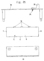
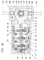
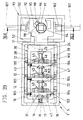
- a permutation lock 1 designed according to the invention is assigned to a piece of furniture 4 having drawers 2, 3.
- the closure housing 5 of the permutation lock is let into the front plate 3 '.
- the closure housing 5, which is designed in the form of an elongated box, has a base 6 with transverse side walls 7, 8 and longitudinal side walls 9, 10 extending therefrom.
- the transverse side walls 7, 8 have an undrotatable, non-displaceable axis of rotation 11 for receiving number disks 12 of circular cross-section arranged next to one another at a distance.
- Each number plate 12 is in coupling tooth engagement to a respective rotatable on the axis of rotation 11 locking sleeve 13 which passes through a central bore of the number plate 12, so that there is an indirect storage thereof on the axis of rotation 11.
- a radially directed projection 14 extends from each locking sleeve 13 and engages in a tooth gap 15 of the number plate 12 in a form-fitting manner. There are ten such tooth gaps in the same circumferential distribution on each number plate 12, so that the locking sleeve 13 can assume ten different positions relative to the number plate 12.
- a compression spring 16 arranged on one free end of the axis of rotation 11 loads the locking sleeves 13 in the engagement direction via a plate 17.
- the displacement of the plate 17 is limited by two webs 18 directed towards the housing and extending from the longitudinal side walls 9, 10.
- pins 19 serve as a rotation lock for the plate 17.
- the webs 18 ensure that the spring force by the plate 17 supported on them no longer acts on the locking sleeves 13.
- radially projecting collars 20 of the locking sleeves 13 engage in recesses 21 facing them on the broad sides of the number disks 12 in a form-fitting manner.
- Each locking sleeve 13 has a truncated cone-shaped annular collar 22 which starts from it and is provided with a flattened portion 23.
- the cross-sectional taper points in the direction of the number disc 12 coupled to it.
- All locking sleeves 13 are arranged on the axis of rotation 11 so that they abut each other.
- An intermediate ring 24 is assigned to the locking sleeve 13 facing the transverse side wall 8.
- Aligned with the slot 27 is a recess of a cover cap 28 which is U-shaped in cross section and extends over the closure housing 5 from below.
- the slot 27 is composed of a slot section 27 'running parallel to the axis of rotation 11 and two slot sections 27' arranged at right angles to this. 'and 27' ''.
- the setting lever 26 is moved from the slot section 27 ′′ into the slot section 27 ′′ ′′ exclusively for the purpose of changing the key secret, cf. Dash-dotted representation in Figure 18.
- a displacement of the adjusting lever 26 causes a displacement of the locking sleeves 13 against spring action, the coupling engagement between the radially directed projections 14 of the locking sleeves 13 and the number disks 12 is canceled. Then these can be brought into a different rotational position and, after returning the adjusting lever 26 to the starting position, come into clutch engagement, the flattened portions 23 of the locking sleeves 13 coming into another position relative to the number disks 12.
- Each number disk 12 is provided on its circumference with ten latching cutouts 29 arranged in the same angular distribution. Between these, each number plate carries the digits from 0 to 9 corresponding to the ten different coupling positions of the locking sleeves 13 the number disks 12.
- the number disks 12 are rotated with the locking sleeves 13 such that their flats 23 face away from the bottom 6 of the closure housing 5 and run parallel to a window slide 30.
- the latter is frame-shaped and has a shorter length than the lock housing 5.
- One frame cross leg 31 is wider than the other frame cross leg 32 and forms a hole 33 in the center for engaging the coupling pin 34 of an operating handle 35.
- Extending between the latter and the window slide 30 is a cover plate 36 which overlaps the closure housing 5 and is provided with recesses 37 in flush alignment with the number disks 12.
- the window slide 30 is supported by the webs 18 as well as by further webs 38 of the longitudinal side walls 9.10.
- the frame longitudinal leg 39 facing the longitudinal side wall 10 continues into an angled portion 40, directed inward of the housing. This is provided with two pins 41 arranged one behind the other at the same height and pointing in the direction of the longitudinal side wall 10, which engage in angular slots 42 of a slide 43. This is guided between the webs 18 and 38 and between the longitudinal side wall 10 and the bend 40.
- the slide 43 thus extends parallel to the axis of rotation 11 and is displaced transversely to its plane of movement when the window slide 30 is displaced by means of the operating handle 35.
- the angular slit 42 is composed of a short slit section 42 ′ directed parallel to the axis of rotation 11 and a longer slit section 42 ′′ which rises up to it.
- the pin 41 In the locked position of the permutation lock, cf. in particular FIGS. 3 and 4, is the pin 41 at the end of the slot portion 42 '. As long as the pin 41 moves in the slot section 42 ', there is no displacement of the slide 43. There is thus an idle stroke of the window slide 30 to the slide 43.
- Each number plate 12 is assigned a locking lever 44, the free end 44 'of which is supported on the lower edge of the slide 43. Furthermore, the locking lever 44 engages with a locking tooth 44 ′′ in one of the locking cutouts 29 of the number plate 12.
- the locking lever 44 is made of the same material from the longitudinal side wall 9 of the closure housing 5, which is preferably made of appropriate plastic.
- Each number plate 12 forms a control curve 45 on the broad surface opposite the recess 21. This is designed as a disk with a heart-shaped circumference.
- the tip 45 'of the heart-shaped control curve points into the area between two mutually adjacent latching cutouts 29.
- a rod-shaped spring element 46 is supported on the heart base 45' 'opposite the heart tip, which runs either flat or fluted.
- the spring element 46 is anchored in the closure housing base 6. It can therefore never occur that the force component exerted by the spring element 46 is conducted into the heart tip 45 '.
- the locking sleeves 13 act together with middle rungs 47 of the window slide 30.
- the rungs 47 extend at a short distance in front of the annular collar 22 of the locking sleeves 13.
- the rungs 47 are supported by means of end journals 48 which enter into cross-section-adapted bores 50 of the longitudinal frame legs 39, 39 '.
- These rungs 47 are designed as spring bridges which are spring-loaded in the locking direction and extend beyond the flats 23 of the locking sleeves 13.
- a torsion spring 50 which is assigned to a bearing journal 48 and which is supported on the one hand on the longitudinal frame leg 39 and on the other hand on a stop web 51 which overlaps the latter, serves for spring loading of each bascule bridge or rung 47.
- Each rung 47 forms a locking edge 47 'on its side facing the operating handle 35, to which a control bevel 47''in the return direction adjoins at an acute angle. Their angle corresponds to that of the frustoconical cross-sectional taper of the ring collar 22.
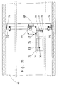
- the frame cross leg 31 bears downward a projection 52 which lies in the open position of the lock in front of the adjusting lever 26 and thus extends in the passage thereof.
- the projection 52 is surmounted by a coupling pin 53. This passes through a slot in both the bottom 6 and the cover cap 28 and engages in an elongated hole 54 of an adapter housing 55. The latter is screwed onto the back of the front plate 3 'of the drawer 3 and also connected to the cover plate 35 while simultaneously fixing the lock housing 5.
- the coupling pin 53 passes through a bore 56 of a link 57, which in turn articulates on an angle lever 58.
- a pin 59 arranged in the area of the angle apex serves to support the same.
- the longer leg of the angle lever 58 has a support pin 60 at its end. This supports through an arch slot 61 of the housing 55 arranged concentrically to the bearing pin 59 and acts on a cross pin 62 on upper end of a central locking rod 63. This in turn is guided in bearings 64 of one side wall 4 'of the piece of furniture 4.
- the central locking rod 63 carries a locking projection 65 which, in the closed position of the permutation lock, lies in front of a laterally protruding projection 66 of the one longitudinal wall 3 '' of the drawer 3 which points in the direction of the side wall 4 '.
- the lower drawer 2 is blocked in the same way.
- the rungs 47 act upon the ring collars 22 of the locking sleeves 13 when the operating handle 35 is shifted in an attempted opening.
- the opening requires the number disks 12 to be turned according to the regulations in accordance with the regulations Figure 7, in which the flats 23 run parallel to the rungs 47.
- the operating handle 35 can now be moved in the direction of the arrow x while simultaneously taking the window slide 30 with it. Its pin 41 passes through the slot section 42 'in an empty path. In the meantime, the rungs 47 run over the annular collars 22 of the locking sleeves 13.
- the projection 52 is carried along. This is then in front of the adjusting lever 26. Furthermore, the coupling pin 53 extending from the projection 52 has shifted the handlebar 47 and rotated the angle lever 58 by this, cf. Figure 23.
- the support pin 60 at the free end of the angle lever 58 allows the central locking rod 63 to be lowered. As a result, the locking projection 65 moves away from the projection 66 of the drawer 3. Only this and the drawer 2 can be pulled out.
- Locking the drawers 2, 3 requires the inserted position of the same. Then the operating handle 35 is to be shifted in the direction of the arrow z, the window slide 30 being carried along. Its rungs 47 step with their control bevel 47 ′′ against the frustoconical flank of the ring collar 22, cf. Figure 12, 15 and 16. This pivots the rungs 47 designed as bascule bridges against spring loading. As soon as the rungs have passed the ring collar 22 of the locking sleeves 13, the rungs 47 pivot into their stop-limited locking position.
- the slide 43 With the relocation of the window slide 30, the slide 43 is moved back by the pin / slot engagement in the direction of the window slide with the release of the spring tongues 44, the Immerse the locking teeth 44 '' in the shape of the locking cutouts 29 in the number disks 12 and adjust them in a locking manner.
- the operating handle 35 is to be shifted from its open position into the closed position according to FIG. 17 when the drawer 3 is open. Then, the protrusion 52 of the window pusher 30 clears the passage for the adjustment lever 26 of the key secret resetting device.
- the free end of the adjusting lever 26, since it passes through a slot of the adapter housing 55 which has the same contour as the slot 27, can be grasped when the drawer 3 is open and can be inserted from the slot section 27 '' into the slot section 27 ''', cf. Fig. 18.
- the locking sleeves 13 are moved over the intermediate ring 24 with simultaneous tensioning of the compression spring 16, cf. Figure 17.
- the radial projections 14 of the locking sleeves 13 consequently come out of engagement with the tooth gaps 15 of the number disks 12. These can now be rotated relative to the locking sleeves 13 while adjusting the new key secret. If the adjusting lever 26 is now moved back, the coupling of the locking sleeves 13 to the number disks 14 takes place.
- the specific basic position which differs from the key secret, can be such that the digits used for the assessment are then zeros.
- the permutation lock 1 works together with an espagnolette lock 67.
- the latter is fixed on the inside of a door 68.
- the espagnolette lock 67 has a bolt 69 and a bushing 71 penetrated by the pivot rod 70.
- the bushing 71 is rotated as a function of the closing movement of the bolt 69.
- Locking hooks 72 are provided on the free ends of the pivot rod 70, which in the closed position of the permutation lock pins on the cabinet 73 reach behind.
- the opening or closing movement of the permutation lock is transmitted by the coupling pin 53 seated on the window slide 30. This engages in a longitudinal slot 74 of an adapter housing 75 and is coupled to a link 76. The latter articulates in the central region of a control lever 78 which can be pivoted about the bearing journal 77. Its free end dips into a closing recess 79 of the bolt 69. According to FIGS. 27 and 28, the closed position of the permutation lock is present. Both the bolt 69 and the locking hook 72 are in the locking position.
- the operating handle 35 of the permutation lock 1 is to be shifted in the opening direction while taking the window slide 30, the coupling pin 53 of which takes the handlebar 76 with it and pivots the control lever 78.
- the bolt 69 is withdrawn and the rotary rod 70 is rotated, whereby the locking hooks 72 reach the pins 73 in a release position, cf. 29 and 30.
- FIGS. 31 and 32 illustrate the interaction of the permutation lock with a sliding door lock 80.
- the coupling pin 53 is now coupled to a link 84 which articulates on a locking hook 81.
- a bolt 82 of the housing 83 of the sliding door lock 80 is used to support the same.
- the locking hook 81 is pivoted over the coupling pin 53 and handlebar 84 such that its free end has entered an opening 85 of a locking plate 86 and this with it Hook underpinned, cf. Fig. 31.
- the opening in turn requires the correct key secret to be set by rotating the number disks as well as shifting the operating handle in the opening direction while simultaneously taking the coupling pin 53, which pivots the locking hook 81 into the position according to FIG. 32 via the handlebar 84.
- the sliding door 87 which carries the permutation lock and the sliding door lock, can accordingly be opened in the direction of the arrow.
- FIGS 33 to 36 illustrate a modified embodiment of the permutation lock 1 '.
- the same parts have the same reference numbers.
- rod-shaped spring elements are missing, which are constantly supported on the heart-shaped control curve 45.
- levers 88 are provided in the same cross-sectional plane to the control cams. Each of these levers 88 is designed as a double lever. Each lever 88 is supported about an axle pin 89 on the lock housing side and aligned parallel to the axis of rotation 11.
- the end of the lever 88 facing the slide 43 is in the pin / slot engagement with the slide 43.
- the shorter lever arm 88 ' is equipped with a cross pin 90 which engages in a transverse slot 91 in the lower region of the slide 43.
- the longer lever arm forms an obliquely rising flank 88 '' which faces the control curve 45 and which, in the closed position, cf. 33, in particular, lies at a distance from the heart-shaped control curve 45.
- a spring tongue 44 is provided, the latching tooth 44' 'of which dips into a latching cutout 29.
- the key secret must be set by turning the number disks 12. Then the flats 23 of the locking sleeves 13 arrive in parallel to the rungs 47 of the window slide, cf. 34.
- the window slide 30 can now be displaced in the direction of the open position by means of the operating handle 35, a downward control of the slide 43 being forced via the pin / slot engagement 41, 42.
- the lever 88 is pivoted about its axis 89. An intermediate position is shown in Figure 35.
- the flank 88 ′′ of the lever 88 comes against the circumferential surface of the heart-shaped control cam 45 and rotates it with the number disk 12 and the locking sleeve 13 into the position according to FIG.
- the tip 45 ′ of the heart curve 45 is thus the number disk 12 assigned that there is a lever arm on the control cam with respect to the axis of rotation 11 in each latching position of the number plate at the time the control cam 45 is acted on.
- the direction of force exerted by the lever 88 via its flank 88 ′′ can therefore never pass through the heart tip 45 ′ and axis of rotation 11. The permutation is therefore adjusted in the open position, so the key secret is not apparent.
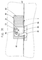
- FIGS. 37 to 44 A further embodiment of the permutation lock 1 ′′ can be seen from FIGS. 37 to 44.
- the window slide 30 is designed, which continues into a bolt tail 92 of a espagnolette lock 93 which projects beyond the transverse side wall 8.
- a longitudinal slot-like recess 94 is machined from the free end of the bolt tail 92.
- a locking engagement recess 95 for the arm 96 of a rotary nut 97 mounted in the espagnolette lock 93 extends from the one narrow edge thereof. Sloping flanks 98, 99 are adjacent to closing engagement opening 95. In the closed position, the radial of the rotating nut passing through the arm 96 runs perpendicular to the oblique flank 98, cf. Fig. 37.
- the bolt tail 92 is equipped on its two outer longitudinal flanks with a coupling pin 100 each, which engages in a longitudinal slot 101 of a rotatable coupling piece 102. This receives a rotary rod 107 in a form-fitting manner, so that when the window slide 30 is moved with the bolt tail 92, a rotary displacement of the rotary rods 107 is caused.
- the spring tongues 103 are designed. They are now supported around an axis 104 on the closure housing side. They receive their spring action at their free end 103 'from a compression spring 105 supported on the bottom 6 of the closure housing 5. Approximately in the central region, the spring tongue 103 forms a locking tooth 106 pointing in the direction of the number plate 12 depending on the rotational position of the number plate 12 with a corresponding latching cutout 29 of the same cooperates.
- the heart-shaped control curve is acted upon 45 also by a rod-shaped spring element 46.
- the heart tip 45 ' is also assigned to the number plate 12 in such a way that the direction of force does not run through the heart tip, so that the heart curve 45 with the number plate 12 is always rotated in one direction or the other until the bottom of the heart 45 '' rests on the rod-shaped spring element 46 and the rotational displacement ends.
- the window slide 30 also continues into a bolt tail 92, on which a rotary actuating handle 110 engages. This is the carrier of a knob 111.
- a rotary nut 97 can be brought from one to the other end position, cf. Fig. 50 and 52.
- the turning nut 97 is also provided with an arm 96 which engages in a locking engagement opening 95 of the bolt tail 92 of the window slide 30.
- a slip clutch 112 is switched on between the window slide 30 or bolt tail 92 and the rotary actuation handle 110.
- the rotating nut 97 is coupled to the rotary actuation handle 110 in such a way that there is a rib / groove engagement which can be disengaged against the spring action.
- a rib 113 with a trapezoidal cross-section extends from the side of the rotary nut 97 facing the rotary actuating handle 110, which rib fits in a form-fitting manner in a diametrical groove 114 of the opposite end of the rotary actuating handle 110.
- the side flanks of the rib 113 and the groove 114 run towards one another in a roof shape.
- the rotary nut 97 is mounted on an axis of rotation 115 anchored in the closure housing 5. At the same time, this passes through a bore 117 of the rotary actuation handle 110 opening into a cup-shaped recess 116.
- the axis of rotation 115 protrudes into the cup-shaped recess 116 and carries a fixed part at a distance from the bottom of the recess its connected plate 118. Between this and the base of the recess extends on the axis of rotation 115 a spring designed as a compression spring 119, which maintains the joint engagement between the rib 113 and the groove 114 to be able to transmit greater forces.
- the above-described slip clutch 112 fulfills the task of overload protection. This is the case if the correct key secret is not set. If the rotary actuation handle 110 is displaced by means of the knob 111, the window slide 30 is carried along by the turning nut 97 by a small amount. until its rungs 47 act on the locking sleeves 13. If the rotary actuation handle 110 is displaced further, this leads to a superimposed axial displacement of the rotary actuation handle 110 against the force of the compression spring 119 occurring over the inclined flanks of the rib 113 and the groove 114, cf. Fig. 51 and 54. The composite engagement or the slip clutch 112 is released so that a further displacement of the rotary operating handle 110 does not exert any constraining forces on the lock mechanism.
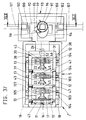
- the three levers 120 arranged one behind the other are connected to one another by a bridge 121.
- Cross pins 122 are formed on the shorter lever arm 120 'of the outside lever 120 and engage in transverse slots 123 of the slide 43.
- a shaft journal 124 which passes through the lever 120 and which lies in slots 125 of the closure housing 5 which are open towards the bottom 6 serves to mount the lever 120.
- Two rod springs 126 extending transversely in the closure housing 5 act on the ends of the axle pin 124 and bring this into abutment position at the bottom of the slots 125, cf. Fig. 47.
- the longer lever arm which is supported in the basic position on the bottom 6 of the closure housing, forms a flank 120 ′′ interacting with the control curve 45.
- the spring tongues 127 assigned to the number disks 12 are mounted about an axis 128 on the housing side.
- Each spring tongue 127 is equipped with a latching tooth 127 ′ which engages in a latching cutout of the number disk 12 under spring load.
- Compression springs 125 which act on the free end of the spring tongues 127, serve for spring loading. The free end of the same lies in the range of movement of the slide 43 and is controlled by the slide 43 as in the aforementioned exemplary embodiments.
- moving the window slide 30 requires the correct setting of the key secret by means of the number disks 12.
- the locking sleeves 13 are rotated so that they allow the rungs 47 of the window slide 30 to pass.
- the window slide 30 effects a downward displacement of the slide 43 via the pin / slot control, the spring tongues 127 being brought out of engagement with the number disks 12.
- the slider 43 pivots the levers 120, which act on the control cam 45 with their flanks 120 ′′ and cause the number disks 12 to rotate into a certain basic position which differs from the key secret, cf. Fig. 48. If the number disc 12 is rotated unnecessarily in this position, a position as shown in Fig. 49 occurs.
- the sloping flank 120 ′′ of the lever 120 is acted upon by the control curve 45. Due to the existing pin / slot engagement between cross pin 122 and cross slot 123, the axle pin 124 is displaced in the downward direction against spring loading, so that no destructive constraining forces occur due to this evasive movement of the lever (s) 120. If the number plate 12 is released from the position according to FIG. 49, the spring load acting on the axle journal 124 brings about the position of the number plate 12 according to FIG. 48.
- adjusting lever 130 is now designed as a pivot lever.
- the adjusting lever 130 is mounted around cross pins 131 near its end engaging the axis of rotation 11.
- a pivoting of the adjusting lever 130 leads to a displacement of the locking sleeves 13 against the compression spring 16 which loads them.
- a displacement is done when the key secret is to be changed.
Landscapes
- Lock And Its Accessories (AREA)
- Purses, Travelling Bags, Baskets, Or Suitcases (AREA)
- Artificial Filaments (AREA)
- Sheet Holders (AREA)
Applications Claiming Priority (4)
| Application Number | Priority Date | Filing Date | Title |
|---|---|---|---|
| DE9106464U | 1991-05-25 | ||
| DE9106464 | 1991-05-25 | ||
| DE9204996U | 1992-04-10 | ||
| DE19929204996 DE9204996U1 (fr) | 1991-05-25 | 1992-04-10 |
Publications (2)
| Publication Number | Publication Date |
|---|---|
| EP0515922A1 true EP0515922A1 (fr) | 1992-12-02 |
| EP0515922B1 EP0515922B1 (fr) | 1995-07-26 |
Family
ID=25958225
Family Applications (1)
| Application Number | Title | Priority Date | Filing Date |
|---|---|---|---|
| EP19920108211 Expired - Lifetime EP0515922B1 (fr) | 1991-05-25 | 1992-05-15 | Serrure à combinaison pour valise, meuble ou similaire |
Country Status (6)
| Country | Link |
|---|---|
| US (1) | US5307657A (fr) |
| EP (1) | EP0515922B1 (fr) |
| JP (1) | JPH05179855A (fr) |
| AT (1) | ATE125590T1 (fr) |
| DE (2) | DE9204996U1 (fr) |
| TW (1) | TW204389B (fr) |
Cited By (3)
| Publication number | Priority date | Publication date | Assignee | Title |
|---|---|---|---|---|
| CN1123503C (zh) * | 1998-03-03 | 2003-10-08 | 西柏控股有限公司 | 一种含有可更换的柔性封装装置的壳体 |
| DE19809481B4 (de) * | 1998-03-06 | 2009-09-24 | Sudhaus Gmbh & Co. | Zahlenschloß für Gepäckstücke, Möbel o. dgl. |
| CN107191069A (zh) * | 2017-06-30 | 2017-09-22 | 刘善华 | 无钥匙锁 |
Families Citing this family (9)
| Publication number | Priority date | Publication date | Assignee | Title |
|---|---|---|---|---|
| US5661991A (en) * | 1996-03-27 | 1997-09-02 | Hsu; Chung-Tang | Combination lock device |
| CN1840842B (zh) * | 2005-04-02 | 2010-09-15 | 彭梁渝 | 自锁码盘式密码防盗锁 |
| CN101417643B (zh) * | 2007-10-26 | 2012-02-15 | 彭梁渝 | 高密汽车防盗器 |
| US7946141B2 (en) * | 2008-04-29 | 2011-05-24 | Kwan Yuen Abraham Ng | Self-scrambling combination lock |
| DE102009016954B4 (de) | 2009-04-14 | 2024-02-01 | Sudhaus Gmbh & Co. Kg | Schlossvorrichtung |
| DE102012005314A1 (de) * | 2012-03-19 | 2013-09-19 | Eduard Hueck Gmbh & Co. Kg | Tür- oder Fensteranordnung |
| GB2543783A (en) | 2015-10-27 | 2017-05-03 | Lowe & Fletcher Ltd | Lock |
| US10392835B2 (en) * | 2017-07-07 | 2019-08-27 | Schlage Lock Company Llc | Combination lock |
| US10851563B1 (en) | 2019-05-30 | 2020-12-01 | Digilock Asia Ltd. | Combination lock with electronic override key |
Citations (4)
| Publication number | Priority date | Publication date | Assignee | Title |
|---|---|---|---|---|
| US2885881A (en) * | 1954-10-04 | 1959-05-12 | Harrison B Syler | Disc-dialing keyless lock |
| DE3246272A1 (de) * | 1981-12-14 | 1983-06-23 | Presto Lock, Inc., 07026 Garfield, N.J. | Permutationsschloss |
| US4770013A (en) * | 1987-03-31 | 1988-09-13 | Clover Co., Ltd. | Combination lock |
| US4905488A (en) * | 1988-04-19 | 1990-03-06 | Clover Co. Ltd. | Dial lock |
Family Cites Families (7)
| Publication number | Priority date | Publication date | Assignee | Title |
|---|---|---|---|---|
| GB207684A (en) * | 1922-10-30 | 1923-12-06 | Laure Fraigneux | Permutation lock for safes and the like |
| US1606279A (en) * | 1925-11-24 | 1926-11-09 | Sesamee Company | Lock |
| US1845021A (en) * | 1931-04-20 | 1932-02-16 | Dudley Lock Corp | Permutation lock |
| US3633388A (en) * | 1970-08-28 | 1972-01-11 | Long Mfg Co Inc | Combination lock construction |
| US4366684A (en) * | 1980-08-25 | 1983-01-04 | Presto Lock, Inc. | Latching device for apertured members |
| US4366687A (en) * | 1981-03-11 | 1983-01-04 | Long Manufacturing Co., Inc. | Changeable combination lock for desk drawers and the like |
| US5007262A (en) * | 1988-04-19 | 1991-04-16 | Clover Co., Ltd. | Dial lock |
-
1992
- 1992-04-10 DE DE19929204996 patent/DE9204996U1/de not_active Expired - Lifetime
- 1992-05-06 US US07/880,178 patent/US5307657A/en not_active Expired - Fee Related
- 1992-05-13 TW TW81103714A patent/TW204389B/zh active
- 1992-05-15 AT AT92108211T patent/ATE125590T1/de active
- 1992-05-15 DE DE59203015T patent/DE59203015D1/de not_active Expired - Fee Related
- 1992-05-15 EP EP19920108211 patent/EP0515922B1/fr not_active Expired - Lifetime
- 1992-05-22 JP JP15605292A patent/JPH05179855A/ja active Pending
Patent Citations (4)
| Publication number | Priority date | Publication date | Assignee | Title |
|---|---|---|---|---|
| US2885881A (en) * | 1954-10-04 | 1959-05-12 | Harrison B Syler | Disc-dialing keyless lock |
| DE3246272A1 (de) * | 1981-12-14 | 1983-06-23 | Presto Lock, Inc., 07026 Garfield, N.J. | Permutationsschloss |
| US4770013A (en) * | 1987-03-31 | 1988-09-13 | Clover Co., Ltd. | Combination lock |
| US4905488A (en) * | 1988-04-19 | 1990-03-06 | Clover Co. Ltd. | Dial lock |
Cited By (3)
| Publication number | Priority date | Publication date | Assignee | Title |
|---|---|---|---|---|
| CN1123503C (zh) * | 1998-03-03 | 2003-10-08 | 西柏控股有限公司 | 一种含有可更换的柔性封装装置的壳体 |
| DE19809481B4 (de) * | 1998-03-06 | 2009-09-24 | Sudhaus Gmbh & Co. | Zahlenschloß für Gepäckstücke, Möbel o. dgl. |
| CN107191069A (zh) * | 2017-06-30 | 2017-09-22 | 刘善华 | 无钥匙锁 |
Also Published As
| Publication number | Publication date |
|---|---|
| ATE125590T1 (de) | 1995-08-15 |
| US5307657A (en) | 1994-05-03 |
| DE59203015D1 (de) | 1995-08-31 |
| EP0515922B1 (fr) | 1995-07-26 |
| DE9204996U1 (fr) | 1992-09-24 |
| TW204389B (fr) | 1993-04-21 |
| JPH05179855A (ja) | 1993-07-20 |
Similar Documents
| Publication | Publication Date | Title |
|---|---|---|
| DE3605826C2 (fr) | ||
| DE3447748C2 (fr) | ||
| DE2839070A1 (de) | Schloss, insbesondere fuer tueren von automobilen | |
| EP0413177A1 (fr) | Serrure pour bielle motrice | |
| DE3836693A1 (de) | Treibstangenschloss | |
| EP0515922B1 (fr) | Serrure à combinaison pour valise, meuble ou similaire | |
| DE3520268C2 (de) | Panikverschluß für eine Ausgangstür | |
| EP0634552B1 (fr) | Clef avec pêne rotatif, spécialement comme serrure supplémentaire à barres coulissantes | |
| DE2850274A1 (de) | Abschliessbarer betaetigungsgriff, insbesondere fuer fenster | |
| DE4019981A1 (de) | Verriegelungsanordnung fuer tueren | |
| EP0677634A1 (fr) | Serrure mortaisée, en particulier pour portes de maison, notamment crémone | |
| WO1996010679A1 (fr) | Fermeture a barre | |
| EP1020597A1 (fr) | Serrure à crémone avec une serrure principal et une serrure complémentaire | |
| DE2049872A1 (de) | Kastenschloß | |
| DE3148030A1 (de) | Zahnradantrieb in einem schliesszylinderbetaetigbaren treibstangenschloss mit schubriegel | |
| EP0381820B1 (fr) | Crémone | |
| DE2552789C2 (de) | Permutationsschloß für Wertbehälter oder dergleichen | |
| EP0496076B1 (fr) | Crémone-serrure | |
| DE3805196C2 (fr) | ||
| EP0823521B1 (fr) | Serrure à crémone | |
| DE3603962A1 (de) | Tuerschloss mit laengs der laengeren seite der tuer angeordneten, mit sperrbolzen versehenen riegelstangen | |
| DE8532525U1 (de) | Treibstangenschloß mit Schließzylinder | |
| EP0806534B1 (fr) | Crémone | |
| AT394607B (de) | Mehrfachverriegelung | |
| DE3630747A1 (de) | Tuerschloss, insbesondere einsteckschloss |
Legal Events
| Date | Code | Title | Description |
|---|---|---|---|
| PUAI | Public reference made under article 153(3) epc to a published international application that has entered the european phase |
Free format text: ORIGINAL CODE: 0009012 |
|
| AK | Designated contracting states |
Kind code of ref document: A1 Designated state(s): AT BE CH DE DK ES FR GB GR IT LI LU MC NL PT SE |
|
| 17P | Request for examination filed |
Effective date: 19930209 |
|
| 17Q | First examination report despatched |
Effective date: 19940826 |
|
| GRAA | (expected) grant |
Free format text: ORIGINAL CODE: 0009210 |
|
| AK | Designated contracting states |
Kind code of ref document: B1 Designated state(s): AT BE CH DE DK ES FR GB GR IT LI LU MC NL PT SE |
|
| PG25 | Lapsed in a contracting state [announced via postgrant information from national office to epo] |
Ref country code: NL Free format text: LAPSE BECAUSE OF FAILURE TO SUBMIT A TRANSLATION OF THE DESCRIPTION OR TO PAY THE FEE WITHIN THE PRESCRIBED TIME-LIMIT Effective date: 19950726 Ref country code: MC Free format text: LAPSE BECAUSE OF NON-PAYMENT OF DUE FEES Effective date: 19950726 Ref country code: GR Free format text: LAPSE BECAUSE OF FAILURE TO SUBMIT A TRANSLATION OF THE DESCRIPTION OR TO PAY THE FEE WITHIN THE PRESCRIBED TIME-LIMIT Effective date: 19950726 Ref country code: ES Free format text: THE PATENT HAS BEEN ANNULLED BY A DECISION OF A NATIONAL AUTHORITY Effective date: 19950726 Ref country code: DK Effective date: 19950726 |
|
| REF | Corresponds to: |
Ref document number: 125590 Country of ref document: AT Date of ref document: 19950815 Kind code of ref document: T |
|
| ET | Fr: translation filed | ||
| REF | Corresponds to: |
Ref document number: 59203015 Country of ref document: DE Date of ref document: 19950831 |
|
| GBT | Gb: translation of ep patent filed (gb section 77(6)(a)/1977) |
Effective date: 19950814 |
|
| ITF | It: translation for a ep patent filed |
Owner name: STUDIO JAUMANN |
|
| PG25 | Lapsed in a contracting state [announced via postgrant information from national office to epo] |
Ref country code: SE Effective date: 19951026 Ref country code: PT Effective date: 19951026 |
|
| NLV1 | Nl: lapsed or annulled due to failure to fulfill the requirements of art. 29p and 29m of the patents act | ||
| PG25 | Lapsed in a contracting state [announced via postgrant information from national office to epo] |
Ref country code: AT Effective date: 19960515 |
|
| PG25 | Lapsed in a contracting state [announced via postgrant information from national office to epo] |
Ref country code: LU Free format text: LAPSE BECAUSE OF NON-PAYMENT OF DUE FEES Effective date: 19960531 Ref country code: LI Effective date: 19960531 Ref country code: CH Effective date: 19960531 |
|
| PLBE | No opposition filed within time limit |
Free format text: ORIGINAL CODE: 0009261 |
|
| STAA | Information on the status of an ep patent application or granted ep patent |
Free format text: STATUS: NO OPPOSITION FILED WITHIN TIME LIMIT |
|
| 26N | No opposition filed | ||
| REG | Reference to a national code |
Ref country code: CH Ref legal event code: PL |
|
| PGFP | Annual fee paid to national office [announced via postgrant information from national office to epo] |
Ref country code: GB Payment date: 19990416 Year of fee payment: 8 |
|
| PGFP | Annual fee paid to national office [announced via postgrant information from national office to epo] |
Ref country code: FR Payment date: 19990420 Year of fee payment: 8 |
|
| PGFP | Annual fee paid to national office [announced via postgrant information from national office to epo] |
Ref country code: DE Payment date: 19990506 Year of fee payment: 8 |
|
| PG25 | Lapsed in a contracting state [announced via postgrant information from national office to epo] |
Ref country code: GB Free format text: LAPSE BECAUSE OF NON-PAYMENT OF DUE FEES Effective date: 20000515 |
|
| GBPC | Gb: european patent ceased through non-payment of renewal fee |
Effective date: 20000515 |
|
| PG25 | Lapsed in a contracting state [announced via postgrant information from national office to epo] |
Ref country code: FR Free format text: LAPSE BECAUSE OF NON-PAYMENT OF DUE FEES Effective date: 20010131 |
|
| PG25 | Lapsed in a contracting state [announced via postgrant information from national office to epo] |
Ref country code: DE Free format text: LAPSE BECAUSE OF NON-PAYMENT OF DUE FEES Effective date: 20010301 |
|
| REG | Reference to a national code |
Ref country code: FR Ref legal event code: ST |
|
| PGFP | Annual fee paid to national office [announced via postgrant information from national office to epo] |
Ref country code: BE Payment date: 20040506 Year of fee payment: 13 |
|
| PG25 | Lapsed in a contracting state [announced via postgrant information from national office to epo] |
Ref country code: IT Free format text: LAPSE BECAUSE OF NON-PAYMENT OF DUE FEES Effective date: 20050515 |
|
| PG25 | Lapsed in a contracting state [announced via postgrant information from national office to epo] |
Ref country code: BE Free format text: LAPSE BECAUSE OF NON-PAYMENT OF DUE FEES Effective date: 20050531 |
|
| BERE | Be: lapsed |
Owner name: S. *FRANZEN SOHNE (G.M.B.H. & CO.) Effective date: 20050531 |
|
| BERE | Be: lapsed |
Owner name: S. *FRANZEN SOHNE (G.M.B.H. & CO.) Effective date: 20050531 |