EP0514877B1 - Apparat zur Unterdrückung von Schwingungen an einem Befestigungsuntergrund - Google Patents
Apparat zur Unterdrückung von Schwingungen an einem Befestigungsuntergrund Download PDFInfo
- Publication number
- EP0514877B1 EP0514877B1 EP92108535A EP92108535A EP0514877B1 EP 0514877 B1 EP0514877 B1 EP 0514877B1 EP 92108535 A EP92108535 A EP 92108535A EP 92108535 A EP92108535 A EP 92108535A EP 0514877 B1 EP0514877 B1 EP 0514877B1
- Authority
- EP
- European Patent Office
- Prior art keywords
- vibration
- magnetic
- floor
- eliminating apparatus
- machine
- Prior art date
- Legal status (The legal status is an assumption and is not a legal conclusion. Google has not performed a legal analysis and makes no representation as to the accuracy of the status listed.)
- Expired - Lifetime
Links
Images


Classifications
-
- F—MECHANICAL ENGINEERING; LIGHTING; HEATING; WEAPONS; BLASTING
- F16—ENGINEERING ELEMENTS AND UNITS; GENERAL MEASURES FOR PRODUCING AND MAINTAINING EFFECTIVE FUNCTIONING OF MACHINES OR INSTALLATIONS; THERMAL INSULATION IN GENERAL
- F16F—SPRINGS; SHOCK-ABSORBERS; MEANS FOR DAMPING VIBRATION
- F16F15/00—Suppression of vibrations in systems; Means or arrangements for avoiding or reducing out-of-balance forces, e.g. due to motion
- F16F15/02—Suppression of vibrations of non-rotating, e.g. reciprocating systems; Suppression of vibrations of rotating systems by use of members not moving with the rotating systems
- F16F15/03—Suppression of vibrations of non-rotating, e.g. reciprocating systems; Suppression of vibrations of rotating systems by use of members not moving with the rotating systems using magnetic or electromagnetic means
-
- G—PHYSICS
- G12—INSTRUMENT DETAILS
- G12B—CONSTRUCTIONAL DETAILS OF INSTRUMENTS, OR COMPARABLE DETAILS OF OTHER APPARATUS, NOT OTHERWISE PROVIDED FOR
- G12B5/00—Adjusting position or attitude, e.g. level, of instruments or other apparatus, or of parts thereof; Compensating for the effects of tilting or acceleration, e.g. for optical apparatus
Definitions
- the present invention relates to a vibration eliminating apparatus for such an apparatus as a semiconductor manufacturing apparatus and an electron microscope, and particularly to a high precision vibration eliminating apparatus for shielding vibration from an installation floor and for controlling a vibration generating force produced by such an apparatus itself, which vibration and vibration generating force give adverse influence on the yield of product and an accuracy in measurement or observation.
- a pneumatic spring or a vibration-proof rubber has been used as an example of a conventional vibration eliminating apparatus.
- Such a machine as an electron microscope and a semiconductor manufacturing apparatus has been mounted on a vibration eliminating floor board provided with pneumatic springs or vibration-proof rubbers so that vibration of an installation floor is absorbed by the pneumatic springs or vibration-proof rubbers to avoid vibration of the floor from giving any adverse influence on the yield of product and an accuracy in measurement by shielding vibration from a machine installed on the vibration eliminating floor board,
- vibration eliminating apparatuses using pneumatic springs or vibration-proof rubbers are mechanical, it has been difficult for such a vibration eliminating apparatus as utilizing pneumatic springs and vibration-proof rubbers to completely eliminate vibration, particularly, small vibration.
- such a vibration eliminating apparatus cannot absorb such large vibration as exceeding a limit of pneumatic spring and vibration-proof rubber and may sometimes give an impact to a machine such as electron microscope mounted on the
- FR-2586462 discloses an apparatus for magnetic suspension of a load comprising a fixed member and a movable member made of magnetic material, wherein one of these members comprises a winding producing an axial magnetic flux.
- This axial magnetic flux is radially diverted at each extremity of the winding by radial polar members leaving a gap between the polar members and the other member that is supported by said one member.
- the two polar members face two layers of permanent magnets that are connected to the fixed member and produce a magnetic flux having lines of force that cooperate with the radial flux generated by the magnetic members to create an axial force of suspension.
- the preamble of claim 1 takes into consideration the art disclosed in FR-2586462.
- a vibration eliminating apparatus as referred to in claim 1 is provided.
- the present invention has been proposed, taking the problems of the prior arts into consideration. It is therefore an object of the present invention to provide a vibration eliminating apparatus for suspending a floor board from an installation floor. It is another object of the present invention to provide a vibration eliminating apparatus for eliminating small vibration of an installation floor by detecting acceleration of a floor board to eliminate vibration thereof. It is a further object of the present invention to provide a vibration eliminating apparatus which monitors vibration of a floor board by a vibration detector provided to the floor board in order to decide whether a vibration level is within an allowable range of a machine mounted on the floor board so as to output an operation enabling signal when a vibration level is within the allowable range, thereby avoiding vibration from giving adverse influence on the yield of product and an accuracy in measurement and observation.
- a vibration eliminating apparatus of the present invention comprises a magnetic member fixed to a floor board and a supporting electromagnet fixed to an installation floor for suspending the magnetic member by a magnetic force.
- the magnetic member fixed to the floor board is surrounded by a thin magnetic pole through a non-magnetic member.
- a control electromagnet is provided to exert a magnetic attracting force to the magnetic pole. The control electromagnet is controlled to eliminate vibration of the floor board by detecting acceleration of the floor board.
- the supporting electromagnet fixed on the installation floor when an exciting current flows therethrough, attracts and suspends the magnetic member by a magnetic attracting force. Therefore, the floor board fixed to the magnetic member can be suspended from the installation floor.
- the magnetic member is surrounded by a thin magnetic pole through a non-magnetic member and a control electromagnet having a yoke is disposed such that the yoke is in the proximity to the thin magnetic pole. Therefore, the floor board can be free from vibration of the installation floor even if a vibration level is low, by exerting a magnetic attracting force to the thin magnetic pole from the yoke of the control electromagnet to cancel vibration by detecting acceleration of the floor board.
- a vibration eliminating apparatus utilizes a spring action by suspending a floor board to eliminate small vibration of an installation floor or a vibration generating force from a machine mounted on the floor board.
- a vibration detector is provided on the floor board to detect vibration of the floor board and a vibration monitor is also provided to monitor the vibration detected by the vibration detector and decide whether a vibration level is within an allowable range of the machine mounted on the floor board or not so as to output an operation enable signal only when a vibration level is within the allowable range.
- a vibration detector provided on a floor board detects vibration of the floor board.
- an operation enable signal is issued and the machine is allowed to operate only when the operation enable signal is output. If a vibration level exceeds the allowable range, the operation enable signal is not output and the machine stops operation. Therefore, the machine operates depending on the existence of the operation enable signal and can operate under the condition that a vibration level is within the allowable range.
- Fig. 1(a) is a plan view of an embodiment of a vibration eliminating apparatus according to the present invention and Fig. 1(b) is a side elevation thereof.
- a floor board 1 is suspended by four actuators 2 comprising electromagnets and mounted on an installation floor 3 to support the floor board 1 at four points as shown in Fig. 1(a).
- a machine such as an electron microscope and a semiconductor manufacturing apparatus which hate vibration.
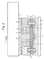
- Fig. 2 illustrates the structure of an actuator of the vibration eliminating apparatus shown in Figs. 1(a) and 1(b).
- the floor board 1 is fixed to a magnetic disk 4 through a supporting member 12.
- the magnetic disk 4 is formed by a magnetic material having a high permeability.
- a supporting electromagnet 5 is fixedly mounted on the installation floor 3.
- the electromagnet 5 comprises a circular yoke 9 around which a coil is wound.
- the yoke 9 is provided facing the magnetic disk 4.
- the yoke 9 and magnetic disk 4 form a magnetic circuit for the supporting electromagnet 5 through a gap between the yoke 9 and disk 4.
- a displacement sensor 8 detects a displacement of the magnetic disk 4 and the floor board 1 relative to the installation floor 3 with a target being provided on the magnetic disk 4.
- a thin magnetic pole 14 is formed around the magnetic disk 4 through a non-magnetic material portion 11.
- Control electromagnets 7 each having a yoke 10 are arranged in the proximity of both ends of the thin magnetic pole 14 with a minute deviation therefrom.
- Each of the yokes 10 has tapered end portions and forms a magnetic circuit with the thin magnetic pole 14 through a gap therebetween.
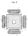
- Fig. 3 illustrates a plan view of the actuator 2 of the vibration eliminating apparatus shown in Figs. 1(a) and 1(b).
- the thin magnetic pole 14 receives horizontal forces by the magnetic shearing forces generated by the yokes 10. Namely, when the control electromagnet 7 disposed at the right side of Fig. 3, the magnetic material disk 4 receives a horizontal force to the right which force is proportional to a level of the exciting current. As explained above, the control electromagnets which are disposed in the proximity to the thin magnetic pole surrounding the magnetic disk 4 can apply a force to the magnetic disk 4 in a desired direction in the horizontal plane.
- Fig. 2 when an exciting current flows through the coil of the supporting electromagnet 5, a magnetic circuit is formed through the gap between the yoke 9 of the supporting electromagnet 5 and the magnetic disk 4, thereby generating a magnetic flux.
- a magnetic attracting force exerted by this magnetic flux serves to suspend the magnetic disk 4.
- the magnetic disk 4 and therefore the floor board 1 are suspended and held from the installation floor 3 at a position where the gravity of the floor board 1 and a machine mounted thereon and a magnetic attracting force exerted by the four electromagnets 5 are balanced. Namely, since the electromagnets 5 are fixedly mounted on the installation floor 3, the floor board 1 on which a machine is mounted is suspended from the installation floor 3.
- the supporting electromagnets 5 merely support the floor board 1 with forces in the vertical direction. With regard to the horizontal direction, the magnetic disk 4 is supported by the magnetic shearing forces generated between the yokes 9 of the supporting electromagnets 5 and the magnetic disk 4 and between the control electromagnets 7 and the thin magnetic pole 14.
- the floor board 1 is provided with the acceleration sensor 6 for controlling the floor board 1 in the horizontal direction in accordance with acceleration in the horizontal direction.
- the acceleration sensor 6 detects acceleration of the floor board 1 in the horizontal direction and excites the control electromagnets 7 so that a magnetic attracting force may be exerted in the horizontal direction to the thin magnetic pole 14 of the magnetic disk 4 to cancel the vibration of the floor board 1.
- the thin magnetic pole 14 is coupled to the magnetic disk 4 through the non-magnetic material portion 11 and the end portions of each of the yokes 10 of the control electromagnets 7 are tapered, enabling intensive magnetic attracting forces to be exerted even when a vibration has a very small amplitude.
- a machine is mounted on the floor board 1 and the floor board 1 is suspended by the actuators 2 from the installation floor 3.
- the floor 3 is considered to be suspended by the actuators 2 from the floor 1.
- the present invention includes both the case where the floor 1 on which a machine is mounted is suspended from floor 3 and the case where the floor 3 on which a machine is mounted is suspended from floor 1.
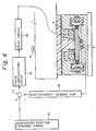
- Fig. 4 is a block diagram of a circuit for controlling in the vertical direction, the vibration eliminating apparatus shown in Figs. 1(a) and 1(b), 2 and 3.
- a desired position of the suspended magnetic disk 4 in the vertical direction is designated by a suspended position command signal 15.
- a comparator 17 compares a suspended position command signal 15 with a signal obtained by amplifying a signal of the displacement sensor 8 by a displacement sensor amplifier 16. If the output of the displacement sensor amplifier 16 does not reach the suspended position command signal 15, the difference therebetween is adjusted in phase by a phase compensating circuit 18, power-amplified by a drive circuit 19 and applied to the coil of the supporting electromagnet 5 as an exciting current.
- Fig. 5 is a block diagram of a circuit for controlling, in the horizontal direction, the vibration eliminating apparatus shown in Fi;gs. 1(a) and 1(b), 2 and 3.
- the acceleration sensor 6 mounted on the floor board 1 detects acceleration applied to the floor board in the horizontal direction.
- the detected acceleration signal is 1 directly input to an amplifying circuit 21, 2 converted to velocity information by integrating the acceleration signal once by an integral circuit 201 and then input to the amplifying circuit 21, or 3 converted to displacement information by integrating the acceleration signal twice by integral circuits 201 and 202 and then input to the amplifying circuit 21.
- the acceleration signal After amplified by the amplifier circuit 21 having a constant gain, the acceleration signal is separated to positive and negative components by a linear and detecting circuit 22. These components are respectively power-amplified by drive circuits 231 and 232 and applied to the coils 13 of the control electromagnets 7R and 7L disposed at the right and left sides.
- the acceleration sensor 6 provided on the floor board 1 to detect acceleration in the horizontal direction can control exciting currents flowing through the supporting electromagnets. Such control enables elimination of vibration in the horizontal and vertical directions of the absolute coordinates system.
- an embodiment of a vibration eliminating apparatus of the present invention can suspend a magnetic disk fixedly mounted to a floor board by magnetic forces exerted by electromagnets fixed to an installation floor.
- a thin magnetic pole is provided around the magnetic disk through a non-magnetic material portion and control electromagnets having yokes located in the vicinity of the magnetic pole are also provided. Therefore, every vibration of the installation floor, from small to large amplitude, can be eliminated by detecting horizontal acceleration of the floor board and exciting the control electromagnets to cancel forces exerted to the floor board.
- the peripheral portion of the magnetic disk is provided with the thin magnetic pole through the non-magnetic material portion and the yokes of the control electromagnets have tapered end portions, vibration of very small amplitude can be eliminated.
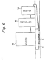
- a machine 32 as a semiconductor manufacturing apparatus and an electron microscope is mounted on a vibration eliminating board 31 and the machine 32 is connected with a machine controller 33.
- the vibration eliminating board 31 includes a vibration detector S.
- a vibration monitor 34 is provided adjacent to the machine 32 and vibration eliminating board 31. Vibration of the vibration eliminating board 31 detected by the vibration detector S is monitored by the vibration monitor 34 (provided in a controller in the case of an active vibration eliminating board) at any time. The vibration monitor 34 is connected with the machine controller 33.
- Vibration of the vibration eliminating board 31 is detected by the vibration detector S mounted on the vibration eliminating board 31, and the detected signal is sent to the vibration monitor 34 (step SP1). Whether vibration X is within an allowable range of the machine 32 or not is decided (step SP2). If the vibration X is within the allowable range, an operation enable signal is sent to the machine controller 33 (step SP3). The machine 32 is operated only when such an operation enable signal is received. If vibration exceeds the allowable range, the operation enable signal is not received and the machine 32 stops operation. Therefore, the machine 32 operates depending on the existence of an operation enable signal and thus can operate under the condition that vibration of the vibration eliminating board 31 is within an allowable range.
- a machine mounted on a vibration eliminating board operates depending on the existence of an operation enable signal issued from a vibration monitor and thus can operate under the environment that vibration of the vibration eliminating board is within an allowable range. As a result, it is possible to avoid such a condition that adverse influence is exerted to the yield of products and an accuracy in measurement and observation.
Landscapes
- Engineering & Computer Science (AREA)
- Physics & Mathematics (AREA)
- General Engineering & Computer Science (AREA)
- Electromagnetism (AREA)
- Acoustics & Sound (AREA)
- Aviation & Aerospace Engineering (AREA)
- Mechanical Engineering (AREA)
- Vibration Prevention Devices (AREA)
Claims (7)
- Schwingungs- bzw. Vibrationsbeseitigungsvorrichtung, welche folgendes aufweist: ein magnetisches Glied (4), das an ersten Bodenmitteln (1) befestigt ist, einen Trag-Elektromagneten (5), der an zweiten Bodenmitteln (3) befestigt ist, um das magnetische Glied (4) mit einer magnetischen Kraft zu tragen bzw. schweben zu lassen,dadurch gekennzeichnet,daß ein Magnetpol (14) durch ein nicht-magnetisches Glied (11) um das magnetische Glied herum angeordnet ist, unddaß ein Steuer-Elektromagnet (7) ein Joch (10) besitzt, das in der Nähe des Magnetpols (14) angeordnet ist.
- Schwingungs- bzw. Vibrationsbeseitigungsvorrichtung gemäß Anspruch 1, wobei eine Maschine auf den ersten Bodenmitteln angebracht ist.
- Schwingungs- bzw. Vibrationsbeseitigungsvorrichtung gemäß Anspruch 2, wobei die ersten Bodenmittel (1) einen Beschleunigungssensor (6) umfassen, und wobei der Steuer-Elektromagnet (7) eine magnetische Anziehungskraft auf den Magnetpol (14) ausübt, um eine abgefühlte Schwingung bzw. Vibration auszugleichen bzw. auszulöschen, und zwar ansprechend auf die Ausgabegröße des Beschleunigungssensors.
- Schwingungs- bzw. Vibrationsbeseitigungsvorrichtung gemäß Anspruch 1, wobei eine Maschine auf den zweiten Bodenmitteln (3) angebracht ist.
- Schwingungs- bzw. Vibrationsbeseitigungsvorrichtung gemäß Anspruch 4, wobei die zweiten Bodenmittel (3) einen Beschleunigungssensor (6) umfassen, und wobei der Steuer-Elektromagnet (7) eine magnetische Anziehungskraft auf den Magnetpol (14) ausübt, um eine abgefühlte Schwingung bzw. Vibration auszugleichen bzw. auszulöschen, und zwar ansprechend auf die Ausgabegröße des Beschleunigungssensors.
- Schwingungs- bzw. Vibrationsbeseitigungsvorrichtung gemäß Anspruch 1, wobei das Joch (10) des Steuer-Elektromagneten (7) einen verjüngten Endteil besitzt und in der Mähe des Magnetpols (14) angeordnet ist.
- Schwingungs- bzw. Vibrationsbeseitigungsvorrichtung gemäß einem der vorhergehenden Ansprüche, wobei die Vorrichtung folgendes aufweist: Schwingungs- bzw. Vibrationsdetektormittel (S) zum Detektieren von Schwingung oder Vibration der Bodenmittel und Schwingungs- bzw. Vibrationsüberwachungsmittel (34) zum Überwachen von Schwingung oder Vibration, die durch die Schwingungs- bzw. Vibrationsdetektormittel (S) detektiert wurde, um zu entscheiden, ob die Schwingung oder Vibration innerhalb eines erlaubten Bereichs ist, und zwar für eine Maschine, die auf den Bodenmitteln (1) angebracht ist, um ein Maschinenbetriebsfreigabesignal nur dann auszugeben, wenn die überwachte Schwingung oder Vibration innerhalb des erlaubten Bereichs ist.
Applications Claiming Priority (4)
| Application Number | Priority Date | Filing Date | Title |
|---|---|---|---|
| JP3143904A JP3051498B2 (ja) | 1991-05-20 | 1991-05-20 | 除振装置 |
| JP143904/91 | 1991-05-20 | ||
| JP35381391A JP2668476B2 (ja) | 1991-12-18 | 1991-12-18 | 除振装置 |
| JP353813/91 | 1991-12-18 |
Publications (3)
| Publication Number | Publication Date |
|---|---|
| EP0514877A2 EP0514877A2 (de) | 1992-11-25 |
| EP0514877A3 EP0514877A3 (en) | 1993-01-20 |
| EP0514877B1 true EP0514877B1 (de) | 1996-01-31 |
Family
ID=26475497
Family Applications (1)
| Application Number | Title | Priority Date | Filing Date |
|---|---|---|---|
| EP92108535A Expired - Lifetime EP0514877B1 (de) | 1991-05-20 | 1992-05-20 | Apparat zur Unterdrückung von Schwingungen an einem Befestigungsuntergrund |
Country Status (3)
| Country | Link |
|---|---|
| US (1) | US5385217A (de) |
| EP (1) | EP0514877B1 (de) |
| DE (1) | DE69207950T2 (de) |
Families Citing this family (26)
| Publication number | Priority date | Publication date | Assignee | Title |
|---|---|---|---|---|
| JPH07111215B2 (ja) * | 1992-08-26 | 1995-11-29 | 鹿島建設株式会社 | 除振装置 |
| JP2816513B2 (ja) * | 1992-08-26 | 1998-10-27 | 鹿島建設株式会社 | 電磁式浮き床構造 |
| GB2281369A (en) * | 1993-06-10 | 1995-03-01 | Mas Research Ltd | Vibration cancellation device |
| JP2954815B2 (ja) * | 1993-06-24 | 1999-09-27 | キヤノン株式会社 | 鉛直方向除振装置 |
| US6989647B1 (en) | 1994-04-01 | 2006-01-24 | Nikon Corporation | Positioning device having dynamically isolated frame, and lithographic device provided with such a positioning device |
| US5874820A (en) * | 1995-04-04 | 1999-02-23 | Nikon Corporation | Window frame-guided stage mechanism |
| US5528118A (en) | 1994-04-01 | 1996-06-18 | Nikon Precision, Inc. | Guideless stage with isolated reaction stage |
| US7365513B1 (en) | 1994-04-01 | 2008-04-29 | Nikon Corporation | Positioning device having dynamically isolated frame, and lithographic device provided with such a positioning device |
| US6154000A (en) * | 1994-09-07 | 2000-11-28 | Omnitek Research & Development, Inc. | Apparatus for providing a controlled deflection and/or actuator apparatus |
| US5604413A (en) * | 1994-09-07 | 1997-02-18 | Polytechnic University | Apparatus for improving operational performance of a machine or device |
| TW318255B (de) | 1995-05-30 | 1997-10-21 | Philips Electronics Nv | |
| US5765800A (en) * | 1995-10-04 | 1998-06-16 | Ebara Corporation | Vibration damping apparatus |
| US5811821A (en) * | 1996-08-09 | 1998-09-22 | Park Scientific Instruments | Single axis vibration reducing system |
| DE19706706C1 (de) * | 1997-02-20 | 1998-07-02 | Deutsch Zentr Luft & Raumfahrt | Verfahren und Anordnung zur Gewinnung eines Fehlersignals an einer Positioniervorrichtung |
| US6487061B1 (en) | 2000-01-27 | 2002-11-26 | Vssi Commercial, Inc. | Electromagnet support system |
| US20030155882A1 (en) * | 2002-02-19 | 2003-08-21 | Nikon Corporation | Anti-gravity mount with air and magnets |
| US7320455B2 (en) * | 2003-10-24 | 2008-01-22 | Newport Corporation | Instrumented platform for vibration-sensitive equipment |
| US7193683B2 (en) * | 2005-01-06 | 2007-03-20 | Nikon Corporation | Stage design for reflective optics |
| JP5603310B2 (ja) * | 2011-10-21 | 2014-10-08 | 本田技研工業株式会社 | エンジン作業機の位置規制装置 |
| US9837939B1 (en) | 2015-04-01 | 2017-12-05 | Lockheed Martin Corporation | System and method for providing vibration isolation by magnetic levitation |
| CN106002877B (zh) * | 2016-07-19 | 2018-05-15 | 苏州誉衡昌精密机械有限公司 | 一种电磁驱动微动工作台 |
| CN106181929B (zh) * | 2016-07-25 | 2018-08-24 | 泰州华龙电子有限公司 | 一种稳定性高的设备支撑台机构 |
| CN106002866B (zh) * | 2016-07-25 | 2018-07-31 | 金华天阳机械股份有限公司 | 一种带安全指示灯的设备支撑台组件 |
| CN106494182B (zh) * | 2016-10-17 | 2019-02-26 | 珠海格力电器股份有限公司 | 减振组件、车载空调及客车和基于电磁技术的减振方法 |
| CN111810582B (zh) * | 2020-07-21 | 2022-02-15 | 西安艾科特声学科技有限公司 | 一种电磁耦合可调谐式两自由度动力吸振器 |
| CN112518364B (zh) * | 2020-10-27 | 2022-07-19 | 合肥哈工联进智能装备有限公司 | 一种用于工装锁紧的脱能式设备 |
Family Cites Families (12)
| Publication number | Priority date | Publication date | Assignee | Title |
|---|---|---|---|---|
| DE230621C (de) * | ||||
| US3464657A (en) * | 1967-08-30 | 1969-09-02 | Us Army | Vibration damped platform |
| US4093931A (en) * | 1977-05-19 | 1978-06-06 | Kohler Co. | Magnetic armature piece for rotary solenoid |
| DE2905973A1 (de) * | 1979-02-16 | 1980-08-28 | Gauting Gmbh Apparatebau | Schwingungstilger |
| JPS5610844A (en) * | 1979-07-02 | 1981-02-03 | Toyota Motor Corp | Feedback control system vibration absorbing suspension |
| DD230621A3 (de) * | 1982-10-14 | 1985-12-04 | Vnii Ochrany Truda I Techniki | Schwingungsdaempfer mit automatischer steuerung |
| FR2586462B1 (fr) * | 1985-08-21 | 1987-10-30 | Alsthom | Dispositif de sustentation magnetique d'une charge |
| US4795123A (en) * | 1987-05-14 | 1989-01-03 | The United States Of America As Represented By The Secretary Of The Air Force | Wideband electromagnetic damping of vibrating structures |
| JPH01131354A (ja) * | 1987-08-27 | 1989-05-24 | Showa Electric Wire & Cable Co Ltd | 精密除振装置 |
| FR2630354B1 (fr) * | 1988-04-20 | 1990-08-31 | Mecanique Magnetique Sa | Dispositif vibrateur actif a suspension magnetique asservie selon trois axes |
| GB8816188D0 (en) * | 1988-07-07 | 1988-11-16 | Marconi Gec Ltd | Mounting for machinery |
| JPH0361746A (ja) * | 1989-07-28 | 1991-03-18 | Nec Corp | 除振装置 |
-
1992
- 1992-05-19 US US07/885,451 patent/US5385217A/en not_active Expired - Lifetime
- 1992-05-20 DE DE69207950T patent/DE69207950T2/de not_active Expired - Fee Related
- 1992-05-20 EP EP92108535A patent/EP0514877B1/de not_active Expired - Lifetime
Also Published As
| Publication number | Publication date |
|---|---|
| DE69207950T2 (de) | 1996-06-05 |
| EP0514877A3 (en) | 1993-01-20 |
| US5385217A (en) | 1995-01-31 |
| EP0514877A2 (de) | 1992-11-25 |
| DE69207950D1 (de) | 1996-03-14 |
Similar Documents
| Publication | Publication Date | Title |
|---|---|---|
| EP0514877B1 (de) | Apparat zur Unterdrückung von Schwingungen an einem Befestigungsuntergrund | |
| EP0767320B1 (de) | Vorrichtung zur Schwingungsdämpfung | |
| US4167296A (en) | Protective control system for magnetic suspension and magnetically suspended devices | |
| EP0584790B1 (de) | Einrichtung zur Beseitigung von Schwingungen des Typs "Null-Kraft Regelung" | |
| EP0814279B1 (de) | Schwingungs-Unterdrückungsvorrichtung | |
| US3976339A (en) | Magnetic suspension apparatus | |
| EP0584791B1 (de) | Schwimmender Boden mit elektromagnetischer Aufhängung | |
| JPH0765635B2 (ja) | 除振台用制振装置 | |
| JP2668476B2 (ja) | 除振装置 | |
| US4339780A (en) | Vibration controller utilizing magnetic forces | |
| JP2893142B2 (ja) | 磁気浮上形除振装置 | |
| JPH0674297A (ja) | 電磁アクチュエータ | |
| JP2522736B2 (ja) | 除振装置 | |
| JPH0366952A (ja) | 振動防止懸垂装置 | |
| WO1990001122A1 (en) | Electromagnetic bearings | |
| US20020011754A1 (en) | Magnetic bearing apparatus | |
| JPH07111214B2 (ja) | 除振装置 | |
| JPH05231471A (ja) | 除振装置 | |
| JP2951488B2 (ja) | 除振装置 | |
| JPH05231472A (ja) | 除振装置 | |
| Chen | Active magnetic bearing design methodology-A conventional rotordynamics approach | |
| JPH01131354A (ja) | 精密除振装置 | |
| JPH0686576A (ja) | 電磁アクチュエータ | |
| JPH06294444A (ja) | 除振装置 | |
| JPH09177879A (ja) | 除振装置 |
Legal Events
| Date | Code | Title | Description |
|---|---|---|---|
| PUAI | Public reference made under article 153(3) epc to a published international application that has entered the european phase |
Free format text: ORIGINAL CODE: 0009012 |
|
| AK | Designated contracting states |
Kind code of ref document: A2 Designated state(s): DE FR GB |
|
| PUAL | Search report despatched |
Free format text: ORIGINAL CODE: 0009013 |
|
| AK | Designated contracting states |
Kind code of ref document: A3 Designated state(s): DE FR GB |
|
| 17P | Request for examination filed |
Effective date: 19930607 |
|
| 17Q | First examination report despatched |
Effective date: 19940629 |
|
| GRAA | (expected) grant |
Free format text: ORIGINAL CODE: 0009210 |
|
| AK | Designated contracting states |
Kind code of ref document: B1 Designated state(s): DE FR GB |
|
| REF | Corresponds to: |
Ref document number: 69207950 Country of ref document: DE Date of ref document: 19960314 |
|
| ET | Fr: translation filed | ||
| PLBE | No opposition filed within time limit |
Free format text: ORIGINAL CODE: 0009261 |
|
| STAA | Information on the status of an ep patent application or granted ep patent |
Free format text: STATUS: NO OPPOSITION FILED WITHIN TIME LIMIT |
|
| 26N | No opposition filed | ||
| REG | Reference to a national code |
Ref country code: GB Ref legal event code: IF02 |
|
| PGFP | Annual fee paid to national office [announced via postgrant information from national office to epo] |
Ref country code: FR Payment date: 20060515 Year of fee payment: 15 |
|
| PGFP | Annual fee paid to national office [announced via postgrant information from national office to epo] |
Ref country code: GB Payment date: 20060517 Year of fee payment: 15 |
|
| PGFP | Annual fee paid to national office [announced via postgrant information from national office to epo] |
Ref country code: DE Payment date: 20060518 Year of fee payment: 15 |
|
| GBPC | Gb: european patent ceased through non-payment of renewal fee |
Effective date: 20070520 |
|
| REG | Reference to a national code |
Ref country code: FR Ref legal event code: ST Effective date: 20080131 |
|
| PG25 | Lapsed in a contracting state [announced via postgrant information from national office to epo] |
Ref country code: DE Free format text: LAPSE BECAUSE OF NON-PAYMENT OF DUE FEES Effective date: 20071201 |
|
| PG25 | Lapsed in a contracting state [announced via postgrant information from national office to epo] |
Ref country code: GB Free format text: LAPSE BECAUSE OF NON-PAYMENT OF DUE FEES Effective date: 20070520 |
|
| PG25 | Lapsed in a contracting state [announced via postgrant information from national office to epo] |
Ref country code: FR Free format text: LAPSE BECAUSE OF NON-PAYMENT OF DUE FEES Effective date: 20070531 |