EP0514320B1 - Elektrostatischer Schussfadenwächter und Webmaschinen mit einem derartigen Schussfadenwächter - Google Patents
Elektrostatischer Schussfadenwächter und Webmaschinen mit einem derartigen Schussfadenwächter Download PDFInfo
- Publication number
- EP0514320B1 EP0514320B1 EP92810263A EP92810263A EP0514320B1 EP 0514320 B1 EP0514320 B1 EP 0514320B1 EP 92810263 A EP92810263 A EP 92810263A EP 92810263 A EP92810263 A EP 92810263A EP 0514320 B1 EP0514320 B1 EP 0514320B1
- Authority
- EP
- European Patent Office
- Prior art keywords
- weft
- sensor element
- weft detector
- feeler
- detector according
- Prior art date
- Legal status (The legal status is an assumption and is not a legal conclusion. Google has not performed a legal analysis and makes no representation as to the accuracy of the status listed.)
- Expired - Lifetime
Links
Images
Classifications
-
- D—TEXTILES; PAPER
- D03—WEAVING
- D03D—WOVEN FABRICS; METHODS OF WEAVING; LOOMS
- D03D45/00—Looms with automatic weft replenishment
- D03D45/50—Cutting, holding, manipulating, or disposing of, weft ends
-
- G—PHYSICS
- G01—MEASURING; TESTING
- G01N—INVESTIGATING OR ANALYSING MATERIALS BY DETERMINING THEIR CHEMICAL OR PHYSICAL PROPERTIES
- G01N33/00—Investigating or analysing materials by specific methods not covered by groups G01N1/00 - G01N31/00
- G01N33/36—Textiles
- G01N33/365—Filiform textiles, e.g. yarns
-
- B—PERFORMING OPERATIONS; TRANSPORTING
- B65—CONVEYING; PACKING; STORING; HANDLING THIN OR FILAMENTARY MATERIAL
- B65H—HANDLING THIN OR FILAMENTARY MATERIAL, e.g. SHEETS, WEBS, CABLES
- B65H63/00—Warning or safety devices, e.g. automatic fault detectors, stop-motions ; Quality control of the package
- B65H63/02—Warning or safety devices, e.g. automatic fault detectors, stop-motions ; Quality control of the package responsive to reduction in material tension, failure of supply, or breakage, of material
- B65H63/024—Warning or safety devices, e.g. automatic fault detectors, stop-motions ; Quality control of the package responsive to reduction in material tension, failure of supply, or breakage, of material responsive to breakage of materials
- B65H63/028—Warning or safety devices, e.g. automatic fault detectors, stop-motions ; Quality control of the package responsive to reduction in material tension, failure of supply, or breakage, of material responsive to breakage of materials characterised by the detecting or sensing element
- B65H63/032—Warning or safety devices, e.g. automatic fault detectors, stop-motions ; Quality control of the package responsive to reduction in material tension, failure of supply, or breakage, of material responsive to breakage of materials characterised by the detecting or sensing element electrical or pneumatic
- B65H63/0321—Warning or safety devices, e.g. automatic fault detectors, stop-motions ; Quality control of the package responsive to reduction in material tension, failure of supply, or breakage, of material responsive to breakage of materials characterised by the detecting or sensing element electrical or pneumatic using electronic actuators
-
- D—TEXTILES; PAPER
- D03—WEAVING
- D03D—WOVEN FABRICS; METHODS OF WEAVING; LOOMS
- D03D51/00—Driving, starting, or stopping arrangements; Automatic stop motions
- D03D51/18—Automatic stop motions
- D03D51/34—Weft stop motions
-
- B—PERFORMING OPERATIONS; TRANSPORTING
- B65—CONVEYING; PACKING; STORING; HANDLING THIN OR FILAMENTARY MATERIAL
- B65H—HANDLING THIN OR FILAMENTARY MATERIAL, e.g. SHEETS, WEBS, CABLES
- B65H2701/00—Handled material; Storage means
- B65H2701/30—Handled filamentary material
- B65H2701/31—Textiles threads or artificial strands of filaments
Definitions
- the invention relates to a weft monitor for weaving machines, the sensor element of which responds or is sensitive to electrical charge of the weft contactlessly, as well as looms in which the weft monitor according to the invention is used.
- a concept for weft monitor is known for example from DE-PS 27 58 403.
- Various embodiments of electrostatic transducers are disclosed therein. These sensors are mainly used for air weaving machines.
- the weft thread is electrically charged with the air during removal from the weft thread supply due to the friction that occurs as well as during the weft insertion due to the friction.
- the electrostatic weft monitor monitors the presence of a textile fiber moving past and in this way electrically charged, in particular the passage of the tip of an inserted weft thread can also be detected.
- Weft monitors are used in the weft channel of the weaving machine.
- the known embodiments are relatively large and heavy and are often designed in the form of a confuser lamella.
- the high-speed air weaving machines customarily used today with a correspondingly high number of strokes of the reed cause high vibration and acceleration loads on the known weft thread monitors, so that the known embodiments for use on air weaving machines are no longer suitable or the resulting electrical signals are very noisy.
- the object of the invention is to produce a non-contact weft monitor based on the electrostatic functional principle, which is particularly suitable for use in high-speed air-jet weaving machines.
- the weft monitor uses a plate-like layered sensor element to contactlessly detect a potential shift in the sensor caused by a weft moving past.
- the sensor element with the sensor facing the weft thread entry, can be inserted between the lamellae of the reed.
- the weft monitor and the sensor element can be variably positioned along the reed, depending on the grid of the slats, and is usually placed directly outside the warp, depending on the weaving width.
- the sensor element is made up of plate-like layers of low mass.
- the outermost, overlying two layers are electrically conductive and serve to shield electrical fields.
- the sensor element, in particular the layers of the sensor are preferably perpendicular to the weft insertion direction.
- the edge of the sensor element facing the weft channel preferably follows the contours of the weft channel in the reed, such as, for example, that of a profile sheet.
- the sensor element can be placed between the Insert lamellae of the reed, which results in a support for the sensor element for the forces, vibrations and accelerations acting in the weft channel direction.
- the rigid, low-mass layered structure is very dimensionally stable and prevents mutual relative movements of the plate-like conductive layers and thus reduces the noise of the electrical signal which occurs under high vibration and acceleration loads, which is caused
- the whole weft monitor is preferably designed as a multi-layer circuit board, the middle conductive layer, in addition to the sensor, also having further conductor tracks for electronic components, in particular a charge amplifier.
- the sensor element can be produced very inexpensively. If an integrated circuit, such as If a charge amplifier is applied directly to the middle layer, a very thin weft monitor can be implemented, which is electrically shielded by the two outer, overlapping plate-like conductive layers. If larger components are used as electronic components, the conductor tracks can also be formed from a partial area of the outermost, electrically conductive layer of the weft monitor and the electronic components can be applied thereon. In addition, a shielding metallic housing is then necessary, which shields the electronic components and the conductor tracks from the outside.
- the weft monitor can be fixed to the reed or the sley using a fastening device. It is preferably inserted between the lamellae of the reed and can be variably positioned along the reed, depending on the grid of the lamellae, such that the sensor element comes to lie outside the weave width.
- the reed can therefore be used for different Weaving widths are left at the original length and the sensor is positioned so that it directly adjoins the warp threads outside the current weaving width, for example. Depending on the width of the woven material, the sensor can therefore be brought into an optimal position along the reed.
- the invention has the advantage that the weft monitor can be arranged largely freely selectable along the reed without changing the functional structure of the weaving machine.
- Another advantage of the sensor element according to the invention is that it is insensitive to contamination.
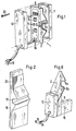
- the weft monitor 1 shows a perspective view of the weft monitor 1 with its subcomponents.
- the weft monitor 1 contains a sensor element 2 and a carrier board 8 for electronic components 9.
- Electrically conductive housing covers 11, 12 protect the interior of the weft monitor 1 thereby enclosed from electrical fields, from mechanical influences and, together with the fastening means 20 designed as screws, and a fastening device 15 to fix the weft monitor 1 on the sley 22 or on the reed 18.
- FIG. 2 shows a reed 18, which is usually constructed from the indicated slats 23.
- the weave of an air-jet weaving machine with an integrated weft channel 19 is shown as an example.
- the sensor 5a of the sensor 2 detects the relatively small potential fluctuations that occur due to the electrically charged thread while it is flying past the sensor 5a.
- a shielded, electrically conductive connection 5b feeds the detected signal to a charge amplifier 10. The elements following charge amplifier 10 for further signal processing and signal processing are not shown.
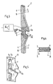
- the sensor element 2 is constructed from plate-shaped layers.
- a middle, electrically conductive layer 5 is surrounded on both sides with an insulating layer 6, 7, on which in turn an electrically conductive layer 3 or 4 is located.
- the three electrically conductive layers 3, 4 and 5 are thin metal layers with a thickness in the micrometer range, the outer layers 3 and 4 being grounded in order to shield the electrical conductors and connections formed with the layer 5 from external electrical fields.
- the insulating layers 6 and 7 are preferably much thicker than the electrically conductive layers 3, 4 and 5 in order to obtain a rigid mechanical sandwich construction.
- the layered structure of the sensor element 2 is realized, for example, with a multilayer printed circuit board.
- the middle electrically conductive layer 5 of the sensor element 2 preferably consists of a metal, such as copper, and has a thickness of a few micrometers.
- the actual sensor 5a in the present exemplary embodiment as an open loop, is formed from this electrically conductive layer 5, the sensor 5a encompassing the firing channel 19 within the profiled sheet 18 in such a way that the cross section of the firing channel 19 is not reduced by the sensor element 2.
- the sensor 5a can of course be formed by different shapes, for example only by the lower half of the shape shown in FIG. 3.
- the middle layer 5 has a conductive connection 5b of the sensor 5a to a charge amplifier 10. Further conductive connections or shielding, grounded layers can be formed from the middle layer 5.
- the sensor 5a is arranged in Fig. 3 so that the side facing the firing channel 19 is electrically conductive towards the outside.
- the sensor 5a can also be integrated into the sensor element 2 in such a way that an electrically insulating layer lies between the firing channel 19 and the sensor 5a on the firing channel side.
- the sensor 5a is less sensitive to contamination.
- an electrical conductor 24 can be applied to the edge facing the weft thread, which is only conductively connected to the sensor 5a.
- the sensor element 2 and the carrier 8 can be combined in a coherent manner if both parts have the same plate-like layered structure and thus form a single part.
- the electronic components 9 are preferably applied to the circuit board 13 using SMD technology in order to avoid holes for their connections.
- the integrated circuits are applied directly to the insulating layer 7 and connected to the conductor tracks 5c.
- a flat weft monitor 1 is created, the electrical components 9, 10 of which are electrically shielded by the outer conductive layers 3 and 4.
- the conductor tracks 5c can also be formed from a partial area of the outermost layer 4 of the carrier 8.
- the conductive connection 5b is plated through to the conductor tracks 5c.
- the electrical shielding of the electronic components 9, 10 is achieved by additional electrically conductive housing covers 11 and 12.
- An electrical connection 16 leads the signal of the sensor 5a amplified at least with a charge amplifier 10 to the outside.
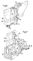
- the weft monitor 1 is with fastening means 20 on the reed 18 or on the sley 22 Detachably attached and penetrates the slats with the sensor 5a. It can be variably positioned along the reed 18, the weft monitor 1 and the sensor element 2 being outside the weaving width and not touching any warp threads.
- the shape of the sensor element 2 is designed such that the sensor element 2 can be inserted between the slats 23 on the weft channel side and that the weft monitor 1 on the weft channel side can be attached to the sley 22, also within the weaving width, in a variably positionable manner.
- FIG. 8 shows a further embodiment of a sensor element 2 with a fastening device 15, which can be fastened in a variably positionable manner on the side of the weaving reed 18 on the weaving sley 23 on the side facing away from the weft channel 19, also within the weaving width.
- the fastening device 15 has the additional property that devices are present which allow the sensor 5a to be positioned in the weft channel 19 of the reed 18 in such a way that the sensor element 2 at least partially grasps the weft channel 19 without projecting into the weft channel 19.
- the weft thread monitor 1 described for air-jet weaving machines is also suitable for other types of weaving machines in which the thread has an electrostatic charge. So this weft monitor is e.g. also suitable for projectile weaving machines.
Landscapes
- Engineering & Computer Science (AREA)
- Textile Engineering (AREA)
- Chemical & Material Sciences (AREA)
- Health & Medical Sciences (AREA)
- Life Sciences & Earth Sciences (AREA)
- Physics & Mathematics (AREA)
- Food Science & Technology (AREA)
- Medicinal Chemistry (AREA)
- Quality & Reliability (AREA)
- Analytical Chemistry (AREA)
- Biochemistry (AREA)
- General Health & Medical Sciences (AREA)
- General Physics & Mathematics (AREA)
- Immunology (AREA)
- Pathology (AREA)
- Looms (AREA)
- Filamentary Materials, Packages, And Safety Devices Therefor (AREA)
Applications Claiming Priority (2)
| Application Number | Priority Date | Filing Date | Title |
|---|---|---|---|
| CH144991 | 1991-05-15 | ||
| CH1449/91 | 1991-05-15 |
Publications (2)
| Publication Number | Publication Date |
|---|---|
| EP0514320A1 EP0514320A1 (de) | 1992-11-19 |
| EP0514320B1 true EP0514320B1 (de) | 1995-11-15 |
Family
ID=4210728
Family Applications (1)
| Application Number | Title | Priority Date | Filing Date |
|---|---|---|---|
| EP92810263A Expired - Lifetime EP0514320B1 (de) | 1991-05-15 | 1992-04-07 | Elektrostatischer Schussfadenwächter und Webmaschinen mit einem derartigen Schussfadenwächter |
Country Status (6)
| Country | Link |
|---|---|
| US (1) | US5205327A (OSRAM) |
| EP (1) | EP0514320B1 (OSRAM) |
| JP (1) | JP2799340B2 (OSRAM) |
| KR (1) | KR100228369B1 (OSRAM) |
| DE (1) | DE59204303D1 (OSRAM) |
| TW (1) | TW208053B (OSRAM) |
Families Citing this family (8)
| Publication number | Priority date | Publication date | Assignee | Title |
|---|---|---|---|---|
| JP2649206B2 (ja) * | 1993-06-23 | 1997-09-03 | 日本セレン株式会社 | シャトルレス織機におけるよこ糸飛走検出装置 |
| EP0744602B1 (de) * | 1995-05-24 | 2002-07-10 | Sulzer Textil AG | Sensor und Vorrichtung mit Sensor zum Detektieren einer Fadenspannung |
| AU5268196A (en) * | 1995-06-02 | 1996-12-18 | Sulzer Ruti Ag | Electrostatic weft stop motion for a shed course loom |
| SE9900791D0 (sv) * | 1999-03-03 | 1999-03-03 | Iro Patent Ag | Method for monitoring weft yarn run/stop conditions |
| EP2216434A1 (de) | 2009-02-10 | 2010-08-11 | ITEMA (Switzerland) Ltd. | Messaufnehmer zur Schusseintragssteuerung |
| KR101320541B1 (ko) * | 2012-03-15 | 2013-10-23 | 주식회사 금강시스템 | 에어제트 직기용 위사감지기 |
| JP7183936B2 (ja) * | 2019-04-24 | 2022-12-06 | 株式会社豊田自動織機 | 織機の緯糸検出装置 |
| DE102019210474A1 (de) * | 2019-07-16 | 2021-01-21 | Deutsche Institute Für Textil- Und Faserforschung Denkendorf | Sensor-Anordnung zum Erfassen zumindest einer physikalischen Kenngröße einer Vielzahl von Fäden |
Family Cites Families (11)
| Publication number | Priority date | Publication date | Assignee | Title |
|---|---|---|---|---|
| FR2125156A1 (en) * | 1971-02-15 | 1972-09-29 | Elitex Zavody Textilniho | Weft thread detector - fitted to air jet shuttless looms |
| DE2140812C3 (de) * | 1971-08-14 | 1978-10-12 | Akzo Gmbh, 5600 Wuppertal | Meßvorrichtung zur Ermittlung von elektrostatischen Aufladungen textiler Fußbodenbeläge |
| CS167623B1 (OSRAM) * | 1973-07-24 | 1976-04-29 | ||
| CS190557B1 (en) * | 1976-12-30 | 1979-05-31 | Vojtech Buran | Detecting element |
| CS193193B1 (en) * | 1976-12-30 | 1979-10-31 | Vojtech Buran | Textile fibre detecting apparatus |
| CH613674A5 (OSRAM) * | 1977-02-10 | 1979-10-15 | Zellweger Uster Ag | |
| JPS6328225Y2 (OSRAM) * | 1980-03-15 | 1988-07-29 | ||
| US4766368A (en) * | 1986-09-30 | 1988-08-23 | Cox Harold A | Capacitive sensor |
| SU1528826A1 (ru) * | 1987-12-01 | 1989-12-15 | Центральный научно-исследовательский институт промышленности лубяных волокон | Устройство дл контрол уточной нити на ткацком станке |
| CH681158A5 (OSRAM) * | 1989-04-07 | 1993-01-29 | Loepfe Ag Geb | |
| US5027253A (en) * | 1990-04-09 | 1991-06-25 | Ibm Corporation | Printed circuit boards and cards having buried thin film capacitors and processing techniques for fabricating said boards and cards |
-
1992
- 1992-03-25 US US07/860,746 patent/US5205327A/en not_active Expired - Fee Related
- 1992-04-07 DE DE59204303T patent/DE59204303D1/de not_active Expired - Fee Related
- 1992-04-07 EP EP92810263A patent/EP0514320B1/de not_active Expired - Lifetime
- 1992-05-13 KR KR1019920008037A patent/KR100228369B1/ko not_active Expired - Fee Related
- 1992-05-14 JP JP4122115A patent/JP2799340B2/ja not_active Expired - Fee Related
- 1992-05-15 TW TW081103819A patent/TW208053B/zh active
Also Published As
| Publication number | Publication date |
|---|---|
| JP2799340B2 (ja) | 1998-09-17 |
| JPH05148744A (ja) | 1993-06-15 |
| EP0514320A1 (de) | 1992-11-19 |
| TW208053B (OSRAM) | 1993-06-21 |
| KR100228369B1 (ko) | 1999-11-01 |
| KR920021772A (ko) | 1992-12-18 |
| DE59204303D1 (de) | 1995-12-21 |
| US5205327A (en) | 1993-04-27 |
Similar Documents
| Publication | Publication Date | Title |
|---|---|---|
| DE69206339T2 (de) | Halbleiterspeichersteuerung und Methode zur Montage in hoher Dichte. | |
| DE10109371B4 (de) | Funkwellenradargerät für Fahrzeuge | |
| DE19637079C2 (de) | Anordnung zur Beschleunigungsmessung | |
| EP0514320B1 (de) | Elektrostatischer Schussfadenwächter und Webmaschinen mit einem derartigen Schussfadenwächter | |
| DE4132985C2 (de) | Leitfähige Matte zur Abschirmung elektromagneticher Wellen | |
| DE69300740T2 (de) | Schirmvorrichtung einer gedrückten schaltungsplatte. | |
| DE2460686C2 (de) | Proportionalzählrohr zur Messung der räumlichen Intensitätsverteilung ionisierender Strahlung | |
| EP0757515B1 (de) | Schaltungsanordnung für Kraftfahrzeuge | |
| CH479478A (de) | Verfahren und Vorrichtung zur Überwachung der Bewegung eines Textilfadens | |
| DE19649848A1 (de) | Elektronischer Schaltkreis mit einem hochfrequenzbedämpfenden Schirmgehäuse | |
| DE69003727T2 (de) | Mobiles Miniatur-Funkgerät mit Abschirmungsanordnung. | |
| DE3790767C2 (de) | Garnbruchdetektor | |
| EP1415397A2 (de) | Kapazitiver näherungssensor zum erfassen von bauelementgur-ten, bauelemente-zufürvorrichtung und verfahren zum erfassen von bauelementgurten | |
| DE60002324T2 (de) | Schutzvorrichtung gegen elektromagnetische strahlung mit dichtungen | |
| DE4408312C2 (de) | Berührungsloser, elektrostatischer Aufnehmer für sich bewegende, längliche und elektrisch nichtleitende Objekte | |
| EP0944108A2 (de) | Strahlungsmesseinrichtung mit einer Ionisationskammer | |
| DE3813610A1 (de) | Winkelmesseinrichtung zum direkten anbau an eine antriebseinheit | |
| DE69631162T2 (de) | Abgeschirmte leiterplatte gegen elektromagnetische interferenzen | |
| DE9214898U1 (de) | Steuergerät | |
| DE102005002866B4 (de) | Sicherheitsgurteinrichtung | |
| DE112020004246T5 (de) | Verschiebungssensor und Verschiebungssensorsystem | |
| DE102018221036A1 (de) | Bedrucktes substrat und drahtloskommunikationsvorrichtung | |
| DE1813153B2 (de) | Kapazitiver messumformer zur umformung mechanischer wegaenderungen in elektrische groessen | |
| EP0155391A1 (de) | Anordnung zum Messen von elektrischen Strömen unter Verwendung eines Magnetfeldsensors | |
| DE3306813A1 (de) | Beschleunigungsaufnehmer |
Legal Events
| Date | Code | Title | Description |
|---|---|---|---|
| PUAI | Public reference made under article 153(3) epc to a published international application that has entered the european phase |
Free format text: ORIGINAL CODE: 0009012 |
|
| AK | Designated contracting states |
Kind code of ref document: A1 Designated state(s): BE DE FR IT SE |
|
| 17P | Request for examination filed |
Effective date: 19930420 |
|
| 17Q | First examination report despatched |
Effective date: 19940902 |
|
| RAP1 | Party data changed (applicant data changed or rights of an application transferred) |
Owner name: SULZER RUETI AG |
|
| GRAA | (expected) grant |
Free format text: ORIGINAL CODE: 0009210 |
|
| AK | Designated contracting states |
Kind code of ref document: B1 Designated state(s): BE DE FR IT SE |
|
| PG25 | Lapsed in a contracting state [announced via postgrant information from national office to epo] |
Ref country code: IT Free format text: LAPSE BECAUSE OF FAILURE TO SUBMIT A TRANSLATION OF THE DESCRIPTION OR TO PAY THE FEE WITHIN THE PRESCRIBED TIME-LIMIT;WARNING: LAPSES OF ITALIAN PATENTS WITH EFFECTIVE DATE BEFORE 2007 MAY HAVE OCCURRED AT ANY TIME BEFORE 2007. THE CORRECT EFFECTIVE DATE MAY BE DIFFERENT FROM THE ONE RECORDED. Effective date: 19951115 Ref country code: FR Effective date: 19951115 |
|
| REF | Corresponds to: |
Ref document number: 59204303 Country of ref document: DE Date of ref document: 19951221 |
|
| PG25 | Lapsed in a contracting state [announced via postgrant information from national office to epo] |
Ref country code: SE Effective date: 19960215 |
|
| EN | Fr: translation not filed | ||
| PLBE | No opposition filed within time limit |
Free format text: ORIGINAL CODE: 0009261 |
|
| 26N | No opposition filed | ||
| PGFP | Annual fee paid to national office [announced via postgrant information from national office to epo] |
Ref country code: DE Payment date: 20050418 Year of fee payment: 14 |
|
| PGFP | Annual fee paid to national office [announced via postgrant information from national office to epo] |
Ref country code: BE Payment date: 20050509 Year of fee payment: 14 |
|
| PG25 | Lapsed in a contracting state [announced via postgrant information from national office to epo] |
Ref country code: BE Free format text: LAPSE BECAUSE OF NON-PAYMENT OF DUE FEES Effective date: 20060430 |
|
| PG25 | Lapsed in a contracting state [announced via postgrant information from national office to epo] |
Ref country code: DE Free format text: LAPSE BECAUSE OF NON-PAYMENT OF DUE FEES Effective date: 20061101 |
|
| BERE | Be: lapsed |
Owner name: *SULZER RUTI A.G. Effective date: 20060430 |