EP0513641B1 - Schmutzfänger für Kraftfahrzeuge - Google Patents
Schmutzfänger für Kraftfahrzeuge Download PDFInfo
- Publication number
- EP0513641B1 EP0513641B1 EP92107606A EP92107606A EP0513641B1 EP 0513641 B1 EP0513641 B1 EP 0513641B1 EP 92107606 A EP92107606 A EP 92107606A EP 92107606 A EP92107606 A EP 92107606A EP 0513641 B1 EP0513641 B1 EP 0513641B1
- Authority
- EP
- European Patent Office
- Prior art keywords
- ribs
- longitudinal
- mud flap
- water
- disposed
- Prior art date
- Legal status (The legal status is an assumption and is not a legal conclusion. Google has not performed a legal analysis and makes no representation as to the accuracy of the status listed.)
- Expired - Lifetime
Links
Images


Classifications
-
- B—PERFORMING OPERATIONS; TRANSPORTING
- B62—LAND VEHICLES FOR TRAVELLING OTHERWISE THAN ON RAILS
- B62D—MOTOR VEHICLES; TRAILERS
- B62D25/00—Superstructure or monocoque structure sub-units; Parts or details thereof not otherwise provided for
- B62D25/08—Front or rear portions
- B62D25/16—Mud-guards or wings; Wheel cover panels
- B62D25/18—Parts or details thereof, e.g. mudguard flaps
- B62D25/188—Mud-guard flaps for utility vehicles
Definitions
- the invention relates to a mud flap for motor vehicles with a flat base made of rubber, plastic or the like, on the rear side of the vehicle wheel facing V-shaped ribs in a central region for collecting, braking and draining water whirled up by the vehicle wheel and in two Channels are arranged symmetrically with respect to the longitudinal center plane and channels are provided for the drainage of the water collected and drained off in the middle region.
- a dirt trap is understood to mean a molded part or plate-shaped material which is adapted to the wheel housing in question and which is cut off in the respective dimensions and is adapted to the geometric conditions of the mounting location. This applies particularly to truck mud flaps.
- the dirt trap can be made of rubber, plastic or another elastomeric material.
- a dirt trap of the type described in the opening paragraph is known from EP-A-302 718.
- the dirt trap is designed as a molded body and has on its rear side facing the vehicle wheel a field with ribs, which are themselves arranged obliquely to the surface of the base body, an angle of 75 ° being preferred.
- the ribs are inclined upwards in a V-shape at least in a central region.
- the ribs can continue in horizontal or downward sloping areas. In the central area, in which experience has shown that the greatest amount of water is produced, the ribs are, however, arranged in an upward V-shape.
- the ribs themselves have walls of parallel design, that is to say they have the same thickness over their height and are delimited at their free ends by roughly sharp edges.
- these channels are formed by walls of C-shaped cross-section, so that the channels are closed towards the rear and can only be filled laterally from the central area. This allows undisturbed drainage of the collected water, provided that the water also reaches these channels and is prevented from being stirred up by the impact in the central area.
- a mud flap for motor vehicles which has a plurality of ribs which are held together by wires or pins and which have the individual surfaces which are arranged and designed such that the water whirled up by the vehicle wheel hits the Strikes surfaces at an acute angle.
- the water should lose part of its speed and give off energy.
- the individual areas of the ribs are arranged in parallel and at a distance from one another, partially assigned to one another in pairs or also designed as longitudinal and transverse webs.
- a surface arranged obliquely to the direction of impact of the spray water is used to deliver energy. No attention is paid to the question of how the decelerated water should be passed on.
- a dirt trap from DE-A-31 02 805 is also known.
- the dirt trap has a flat base body, on the rear side of which faces the vehicle wheel, projections are provided as flexible individual elements in the form of slender, at least substantially upright plugs or extensions. These projections have approximately cylindrical or frustoconical shape, tapering towards their free end and are arranged in an asymmetrical distribution on the main surface of the base body without any relation to one another as individual elements. The distances between the individual elements or projections are designed differently.
- the projections are intended to slow down the impact energy of water drops and influence the direction of the rebounding water droplets in such a way that the formation of dangerous spray mist is avoided.
- the projections are intended to counteract the adherence and accumulation of dirt on the back of the base body, so that an advantageous self-cleaning effect should be present due to the shaking movements that occur during operation.
- a reduction in the spray which occurs is only possible to a certain extent here.
- the surface area of the main surface or rear of the dirt trap is relatively high, on which the water whirled up by the vehicle wheel is thrown in a more or less vertical direction hits, so that the individual drops of water are subjected to a bursting or atomizing effect, which does not lead to a reduction in the spray effect.
- such water drops that hit the projections are caught, braked and drained, the water being drained off in an uncontrolled manner on all sides.
- mud and snow are often whirled up or thrown off the vehicle tires. In appropriate climatic conditions, this can lead to the formation of a closed layer of ice on the rear of the strainer, which leads to a leveling of the surface of the strainer, so that any advantageous effect is eliminated.
- the basic body of such a strainer must be designed to be comparatively stable because it has to provide the shape of the strainer, also against the pressure of the wind and the whirled up water jet.
- the projections have to be designed very flexibly so that a noticeable shaking effect can be determined by the vibrations occurring, two different material mixtures made of rubber or other elastomer often have to be used and pressed together, as a result of which the production of such dirt traps becomes complex and expensive. If the number of protrusions on the rear of the mud flap is increased, the braking effect is also increased. On the other hand, the production becomes more problematic because the depressions in the tools can become clogged during pressing, and the more so, the finer and slimmer the individual frustoconical objects are designed and designed.
- the invention has for its object to develop a strainer of the type described in such a way that it discharges a very large part of the sprayed water, in particular more than 70%, reliably downwards, so that the formation of spray mist is counteracted in this way.
- a dirt trap of the type described in the introduction in that the ribs are provided in a V-shaped downward inclination from their apex in the longitudinal center plane, have a cross section which tapers in the direction from the base body to its free end and are thus arranged close to one another that the depressions between the ribs have approximately the same cross-sectional area, of course in the reverse order to the cross-sectional area of the ribs, and that the channels arranged in the side areas are designed to be open on the side facing the vehicle wheel and have at least two continuous longitudinal ribs, of which the longitudinal rib facing the longitudinal center plane has a lower height than the longitudinal rib facing the longitudinal edge of the strainer.
- the invention is based on the idea that the water whirled up by the vehicle wheel, which strikes the central region of the dirt trap, must first be collected and braked.
- the ribs which are arranged comparatively close to one another, so that there are practically everywhere boundary surfaces of the ribs with which the swirled water comes into braking contact.
- the surface of the base body which is essentially perpendicular to the spraying direction of the water is thus not used for collecting the water.
- the depressions formed between the ribs, in conjunction with the V-shaped downward inclination of the ribs, serve to discharge the collected water to the right and left of the longitudinal center plane of the strainer, the water being conducted in comparatively narrow channels.
- the channels arranged in the side area are designed to face the vehicle wheel so that water that is thrown off the side of the vehicle wheel can strike a water film coming down and is carried along by it.
- the longitudinal ribs are arranged at an appropriate distance from one another, so that here a flat, not too thick water film results, which flows downwards.
- the longitudinal rib facing the median longitudinal plane acts as a tripping threshold. It has a reduced height compared to the other longitudinal rib, so that here part of the water brought in from the depressions of the V-shaped ribs can pass over the first longitudinal rib, while another part does not make this transition and can pass in front of the first longitudinal rib flows out below.
- the first longitudinal rib also acts as a dividing element for the water.
- more than two longitudinal ribs can be provided, it being expedient to let the height of the longitudinal ribs increase in steps from the inside to the end, in order to ultimately ensure that no water passes over the longitudinal edges of the strainer, but all the water is drained down over the transverse edge.
- the V-shaped ribs should be at an angle to the horizontal in a range of 18 to 22 °, preferably about 20 °. Experiments have shown that this angular range is advantageous insofar as the water particles collected are discharged parallel to the straight extension of the ribs or depressions in the latter due to the influence of gravity and the air flow in the wheel arch housing. There is neither a build-up of water to be observed nor a passage of water particles across the individual ribs transversely to their direction of extension.
- the ribs arranged in a V-shape should have a height of 15 to 20 mm, preferably approximately 17 mm, and a distance from one another of 8 to 12 mm, preferably approximately 10 mm. This means that the ribs are comparatively close to each other and there is practically an oblique braking surface on the ribs for each water particle in order to release energy. However, it is also possible to enlarge or reduce the geometry of the ribs and depressions as a whole while observing the conditions that are formed.
- the flanks of the ribs can have an angle of approximately 16 to 18 ° and the free end of the ribs can be rounded.
- the aim is not to catch the water particles on the free ends of the ribs, but rather on their flanks, these flanks being arranged at a very flat angle obliquely to the direction of impact of the water particles thrown off the vehicle wheel.
- V-shaped ribs themselves are provided at a right angle to the main body, i. H. a center line of the ribs extends perpendicular to the base body.
- the longitudinal rib facing the longitudinal center plane can have a height of approximately 7 mm and the other longitudinal ribs of approximately 15 to 20 mm, preferably approximately 17 mm.
- the first longitudinal median plane thus initially has a dividing function in the direction of the water released from the free ends of the depressions. Part of the water will pass over this first longitudinal rib, a second part of the water will be slowed down. This creates a separate channel to the right and left of the first longitudinal rib, through which the water that is divided off is led downwards.
- a plurality of longitudinal ribs can also be provided, the height of which is appropriately stepped from the inside to the outside.
- the outermost longitudinal rib which is arranged on the longitudinal edge of the mud flap, should be of such a height that, as far as possible, no water can pass over it, because this transfer of water is associated with side detachment phenomena from the mud flap, which in turn increases the formation of spray mist.
- the longitudinal rib facing the longitudinal center plane can be arranged at a distance from the free end of the V-shaped ribs and distances can also be provided between the other longitudinal ribs. These distances are relatively wide, so that here flat areas are provided for the drainage of the water in a thin, veil-like curtain.
- the longitudinal ribs are also expediently provided at right angles to the main body. This not only serves to easily remove the dirt body from the mold or injection mold, but also provides the guarantee that the Longitudinal ribs optimally fulfill their braking and deflection function for the water collected.
- the central region in which the V-shaped ribs are arranged can have approximately half of the region of the base body.
- the central area is designed to be slightly larger than the remaining surface of the base body.
- the channels open to the rear in the side areas are, however, unusually wide - in relation to the extent of the central area.
- the longitudinal ribs are provided with a free end at the lower edge of the base body, so that the water which is led down in partial flows can leave the lower transverse edge of the strainer without hindrance. This is an area in which the air flow has comparatively lower speeds, so that the risk of spray formation when detaching is largely reduced.
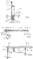
- the dirt trap has a flat base body 1, as can also be seen particularly clearly from FIG. 2.
- the dirt trap is already formed here as a molded body and has an upper transverse edge 2, a lower transverse edge 3 and two longitudinal edges 4 and 5.
- a fastening strip 6 extends along the upper transverse edge 2 and is used for attachment to the vehicle.
- the fastening strip 6 is delimited by a transverse rib 7.
- Below the transverse rib 7, the base body 1 forms a tab main body which, like the fastening strip 6, is formed symmetrically to a longitudinal center plane 8. To the right and left of the longitudinal median plane 8 in the direction of the longitudinal edges 4 and 5, a central region 9 and two side regions 10 initially extend.
- ribs 11 are provided which are straight and are arranged relatively close to one another, as is the case here also emerges from Figures 2 and 6. Apart from their apex arranged in the longitudinal center plane 8, the ribs 11 extend in a straight line, wherein they are arranged in a V-shape and inclined downwards.
- the angle 12 between a horizontal 13 and the leg of the ribs 11 is in the range from 18 to 22 °, preferably approximately 20 °.
- Recesses 14 extend between the ribs 11, which also run in a straight line due to the arrangement of the ribs and openly merge into the surface of the base body 1.
- the respective side area 10 begins, which extends up to the longitudinal edges 4 or. 5 extends.
- the area of the central region 9, in which the V-shaped ribs 11 are arranged, is slightly larger than the surface of the two side regions 10.
- Figure 2 shows the formation of the ribs 11 and the recesses 14 arranged between them in detail.
- the ribs 11 and the depressions 14 have approximately the same Cross-sectional area, but in reverse order.
- the ribs 11 are arranged at a distance 15 from one another, which can be approximately 10 mm.
- the height 16 of the ribs 11 is 17 mm and the thickness 17 of the base body 15 mm.
- the ribs 11 are tapered towards their free end so that there is an inverted cross-sectional arrangement for the depressions 14.
- the free ends 18 of the ribs 11 are rounded.
- the flanks 19 of the ribs 11 run obliquely, that is to say not at right angles, to the main plane of the base body 1.
- Figures 3 and 4 illustrate the formation in the side regions 10.
- a first longitudinal rib 20, a second longitudinal rib 21 and a third longitudinal rib 22 are provided, which extend from top to bottom continuously over each side region 10 parallel to the longitudinal edges 4 and 5 .
- the first longitudinal rib 20 is arranged facing the longitudinal center plane 8 of the strainer or represents the first longitudinal rib, viewed from the inside outward in the direction of flow of the water.
- a distance 23 is provided between the lateral free end of the ribs 11 and the longitudinal rib 20, which in the exemplary embodiment shown can be 30 mm.
- a first channel 24 is formed here in order to divert a portion of the water collected and braked in the central region 9 downward parallel to the edges 4 and 5.
- This direction of discharge of a portion of the water is indicated by an arrow 25.
- Another subset will overcome the longitudinal rib 20 and reach the area of a channel 26 which is formed between the ribs 20 and 21 and move downward there according to arrow 27.
- the ribs 20 and 21 are arranged at a distance 28, which is here, for example, 50 mm.
- the channels 24, 26 and 29 are open to the front, that is to say pointing from the rear of the dirt trap in the direction of travel.
- the first longitudinal rib 20 has a lower height than the longitudinal rib 21 following in the direction of flow.
- At least two longitudinal ribs 20 and 21 should be provided.
- the number of longitudinal ribs can also be increased, as shown, with three longitudinal ribs 20, 21, 22 being arranged in the manner shown in the drawings.
- the longitudinal ribs 20, 21, 22 also taper conically on their free end. Their two flanks 31, 32 form an angle 33 with one another, which can be 17 ° +/- 1 °.
- the flanks 19 of the ribs 11 are designed in a similar manner.
- there is an angle 34 which is expediently 17 ° +/- 1 °.
- Figure 5 illustrates the arrangement of the dirt trap relative to the vehicle wheel 35.
- the direction of travel of the vehicle is indicated by arrow 36.
- the base body 1 of the dirt trap is arranged so that its ribs 11 are arranged facing the vehicle wheel 35.
- the water whirled up by the vehicle wheel 35 reaches according to the rays 37 obliquely onto the flanks 19 of the ribs 11 and is braked or broken there so that it loses considerable kinetic energy.
- Gravity acts on the collected and braked water on the one hand and forces exerted by the air movement in the wheel housing on the other.
- strainer With the newly designed strainer, it is possible to catch up to almost 80% of the sprayed water, slow it down and bring it downwards in accordance with the applicable test regulations. In one experiment, 77% were measured. The strainer thus absorbs 77% of the water sprayed according to Official Journal of the European Community No C 263/19.
Landscapes
- Engineering & Computer Science (AREA)
- Chemical & Material Sciences (AREA)
- Combustion & Propulsion (AREA)
- Transportation (AREA)
- Mechanical Engineering (AREA)
- Body Structure For Vehicles (AREA)
Applications Claiming Priority (2)
| Application Number | Priority Date | Filing Date | Title |
|---|---|---|---|
| DE4115516A DE4115516A1 (de) | 1991-05-11 | 1991-05-11 | Schmutzfaenger fuer kraftfahrzeuge |
| DE4115516 | 1991-05-11 |
Publications (2)
| Publication Number | Publication Date |
|---|---|
| EP0513641A1 EP0513641A1 (de) | 1992-11-19 |
| EP0513641B1 true EP0513641B1 (de) | 1994-12-14 |
Family
ID=6431529
Family Applications (1)
| Application Number | Title | Priority Date | Filing Date |
|---|---|---|---|
| EP92107606A Expired - Lifetime EP0513641B1 (de) | 1991-05-11 | 1992-05-06 | Schmutzfänger für Kraftfahrzeuge |
Country Status (5)
| Country | Link |
|---|---|
| US (1) | US5205590A (enExample) |
| EP (1) | EP0513641B1 (enExample) |
| CA (1) | CA2068370A1 (enExample) |
| DE (2) | DE4115516A1 (enExample) |
| ES (1) | ES2065103T3 (enExample) |
Families Citing this family (11)
| Publication number | Priority date | Publication date | Assignee | Title |
|---|---|---|---|---|
| US5366247A (en) * | 1993-05-10 | 1994-11-22 | Fischer Kenneth J | Vehicle splashguard |
| GB2322346A (en) * | 1997-02-21 | 1998-08-26 | Parlok Ab Oy | Spray suppression device |
| US6139062A (en) * | 1998-08-18 | 2000-10-31 | Meyer; Darin | Mud flap lifter |
| DE19919250A1 (de) * | 1999-04-28 | 2000-11-02 | Bayerische Motoren Werke Ag | Spritzschutz für Fahrzeuge mit Rädern |
| US20110214568A1 (en) * | 2003-03-12 | 2011-09-08 | Jeffrey Krantz | System and method for removing brake dust and other pollutants |
| US7625013B2 (en) * | 2006-10-25 | 2009-12-01 | Solutia, Inc. | Spray suppression device for vehicles |
| US8146949B2 (en) | 2009-09-02 | 2012-04-03 | Tarun Natwarlal Surti | Mud flap |
| USD685306S1 (en) * | 2012-04-27 | 2013-07-02 | Fleet Engineers, Inc. | Mudflap |
| MX2013006298A (es) * | 2012-06-05 | 2013-12-16 | Fleet Engineers Inc | Guardafango aerodinamico. |
| DE102013107109B4 (de) * | 2013-07-05 | 2019-02-07 | Kögel Trailer GmbH & Co. KG | Antisprayschürze, Nutzfahrzeugaufbau und Nutzfahrzeug mit einer derartigen Antisprayschürze |
| US10435083B2 (en) * | 2016-08-10 | 2019-10-08 | Ekostinger, Inc. | Aerodynamic recapture method and apparatus |
Family Cites Families (10)
| Publication number | Priority date | Publication date | Assignee | Title |
|---|---|---|---|---|
| US1904343A (en) * | 1932-06-15 | 1933-04-18 | Zaiger Max | Splash flap for automobiles |
| US2714015A (en) * | 1954-07-19 | 1955-07-26 | Chester E Sherman | Splash guard for vehicle wheels |
| DE2045212A1 (de) * | 1969-09-12 | 1971-03-18 | Moss, Trevor Frederick, Noss Mayo (Großbritannien) | Spritzschutz für Fahrzeuge |
| GB2084094A (en) * | 1980-09-11 | 1982-04-07 | Typrod Ltd | A spray reducing device for a vehicle |
| DE3102805A1 (de) * | 1981-01-28 | 1982-09-02 | Dunlop Ag, 6450 Hanau | Vorrichtung zur beseitigung stoerender spruehwasserbildung durch fahrzeugreifen |
| US4382606A (en) * | 1981-02-02 | 1983-05-10 | Lancaster Colony Corporation | Spray controlling system and splash guard for automotive vehicles |
| US4796905A (en) * | 1985-05-03 | 1989-01-10 | Sullivan Patrick F | Spray-suppressant surface configuration |
| ES2033323T3 (es) * | 1986-10-31 | 1993-03-16 | Patrick F. Sullivan | Material y dispositivos de supresion de rociadas o salpicaduras para vehiculos de carretera. |
| EP0302718A1 (en) * | 1987-08-06 | 1989-02-08 | Abal Engineering Limited | Spray suppression flap |
| US5022680A (en) * | 1989-08-16 | 1991-06-11 | Fleet Engineers, Inc. | Spray-suppressant splash guard for vehicles |
-
1991
- 1991-05-11 DE DE4115516A patent/DE4115516A1/de active Granted
-
1992
- 1992-05-06 ES ES92107606T patent/ES2065103T3/es not_active Expired - Lifetime
- 1992-05-06 EP EP92107606A patent/EP0513641B1/de not_active Expired - Lifetime
- 1992-05-06 DE DE59200943T patent/DE59200943D1/de not_active Expired - Fee Related
- 1992-05-08 US US07/880,029 patent/US5205590A/en not_active Expired - Fee Related
- 1992-05-11 CA CA002068370A patent/CA2068370A1/en not_active Abandoned
Also Published As
| Publication number | Publication date |
|---|---|
| DE4115516C2 (enExample) | 1993-08-05 |
| CA2068370A1 (en) | 1992-11-12 |
| DE4115516A1 (de) | 1992-11-12 |
| EP0513641A1 (de) | 1992-11-19 |
| DE59200943D1 (de) | 1995-01-26 |
| ES2065103T3 (es) | 1995-02-01 |
| US5205590A (en) | 1993-04-27 |
Similar Documents
| Publication | Publication Date | Title |
|---|---|---|
| EP0062137B1 (de) | Kotflügel für Kraftfahrzeuge, insbesondere Lastkraftwagen | |
| EP0513641B1 (de) | Schmutzfänger für Kraftfahrzeuge | |
| DE202021103722U1 (de) | Motorradkotflügel und damit versehenes Motorrad | |
| EP3484600A1 (de) | Tropfenabscheider und tropfenabscheiderlamelle mit interner entwässerung | |
| DE2429467C3 (de) | Schmutzfängerlappen für Kraftfahrzeuge | |
| DE1505251C3 (de) | Schmutzfänger zum Anbringen hinter Fahrzeugrädern | |
| WO2003013918A1 (de) | Wischblatt, insbesondere flachwischblatt | |
| EP0973597A1 (de) | Filterlement aus zusammengesinterten kunststoffteilchen | |
| DE3823786A1 (de) | Schmutzfaenger fuer kraftfahrzeugrad-kotfluegel | |
| DE3102805C2 (enExample) | ||
| DE2719879C2 (enExample) | ||
| EP0353494B1 (de) | Kraftfahrzeugkotflügel mit Spritzwasserschutz | |
| DE3779564T2 (de) | Spritzbeseitigungsmaterial und vorrichtungen fuer strassenfahrzeuge. | |
| DE2045212A1 (de) | Spritzschutz für Fahrzeuge | |
| DE10346710B4 (de) | Spritzwasserschutzvorrichtung | |
| EP0396873B1 (de) | Schmutzfangeinrichtung | |
| DE3922715C2 (enExample) | ||
| DE4200722A1 (de) | Spritzwasserfaenger fuer das vom fahrzeugrad aufgewirbelte wasser | |
| EP1911502B1 (de) | Tropfenabscheideranordnung | |
| EP0825095B1 (de) | Spritzwasserfänger für Fahrzeuge | |
| DE9110684U1 (de) | Spritzwasserfänger für das vom Fahrzeugrad aufgewirbelte Wasser | |
| DE29614737U1 (de) | Kotflügelelemente, insbesondere zur Sprühnebelunterdrückung im Fahrzeugbereich | |
| DE4027073A1 (de) | Vorrichtung zur beseitigung stoerender spruehwasserbildung durch fahrzeugreifen | |
| DE249800C (enExample) | ||
| DE3636909A1 (de) | Schmutz- und wasserfaenger fuer kraftfahrzeuge |
Legal Events
| Date | Code | Title | Description |
|---|---|---|---|
| PUAI | Public reference made under article 153(3) epc to a published international application that has entered the european phase |
Free format text: ORIGINAL CODE: 0009012 |
|
| AK | Designated contracting states |
Kind code of ref document: A1 Designated state(s): DE ES FR GB IT |
|
| 17P | Request for examination filed |
Effective date: 19921006 |
|
| 17Q | First examination report despatched |
Effective date: 19940208 |
|
| ITF | It: translation for a ep patent filed | ||
| GRAA | (expected) grant |
Free format text: ORIGINAL CODE: 0009210 |
|
| AK | Designated contracting states |
Kind code of ref document: B1 Designated state(s): DE ES FR GB IT |
|
| REF | Corresponds to: |
Ref document number: 59200943 Country of ref document: DE Date of ref document: 19950126 |
|
| REG | Reference to a national code |
Ref country code: ES Ref legal event code: FG2A Ref document number: 2065103 Country of ref document: ES Kind code of ref document: T3 |
|
| GBT | Gb: translation of ep patent filed (gb section 77(6)(a)/1977) |
Effective date: 19950111 |
|
| ET | Fr: translation filed | ||
| PLBE | No opposition filed within time limit |
Free format text: ORIGINAL CODE: 0009261 |
|
| STAA | Information on the status of an ep patent application or granted ep patent |
Free format text: STATUS: NO OPPOSITION FILED WITHIN TIME LIMIT |
|
| 26N | No opposition filed | ||
| REG | Reference to a national code |
Ref country code: GB Ref legal event code: IF02 |
|
| PGFP | Annual fee paid to national office [announced via postgrant information from national office to epo] |
Ref country code: GB Payment date: 20030701 Year of fee payment: 12 |
|
| PGFP | Annual fee paid to national office [announced via postgrant information from national office to epo] |
Ref country code: DE Payment date: 20030707 Year of fee payment: 12 |
|
| PGFP | Annual fee paid to national office [announced via postgrant information from national office to epo] |
Ref country code: FR Payment date: 20030721 Year of fee payment: 12 |
|
| PGFP | Annual fee paid to national office [announced via postgrant information from national office to epo] |
Ref country code: ES Payment date: 20030728 Year of fee payment: 12 |
|
| PG25 | Lapsed in a contracting state [announced via postgrant information from national office to epo] |
Ref country code: GB Free format text: LAPSE BECAUSE OF NON-PAYMENT OF DUE FEES Effective date: 20040506 |
|
| PG25 | Lapsed in a contracting state [announced via postgrant information from national office to epo] |
Ref country code: ES Free format text: LAPSE BECAUSE OF NON-PAYMENT OF DUE FEES Effective date: 20040507 |
|
| PG25 | Lapsed in a contracting state [announced via postgrant information from national office to epo] |
Ref country code: DE Free format text: LAPSE BECAUSE OF NON-PAYMENT OF DUE FEES Effective date: 20041201 |
|
| GBPC | Gb: european patent ceased through non-payment of renewal fee |
Effective date: 20040506 |
|
| PG25 | Lapsed in a contracting state [announced via postgrant information from national office to epo] |
Ref country code: FR Free format text: LAPSE BECAUSE OF NON-PAYMENT OF DUE FEES Effective date: 20050131 |
|
| REG | Reference to a national code |
Ref country code: FR Ref legal event code: ST |
|
| PG25 | Lapsed in a contracting state [announced via postgrant information from national office to epo] |
Ref country code: IT Free format text: LAPSE BECAUSE OF NON-PAYMENT OF DUE FEES;WARNING: LAPSES OF ITALIAN PATENTS WITH EFFECTIVE DATE BEFORE 2007 MAY HAVE OCCURRED AT ANY TIME BEFORE 2007. THE CORRECT EFFECTIVE DATE MAY BE DIFFERENT FROM THE ONE RECORDED. Effective date: 20050506 |
|
| REG | Reference to a national code |
Ref country code: ES Ref legal event code: FD2A Effective date: 20040507 |