EP0512657B1 - Vorrichtung zum Kuppeln der Stromzuführung zu einem metallurgischen Gefäss - Google Patents
Vorrichtung zum Kuppeln der Stromzuführung zu einem metallurgischen Gefäss Download PDFInfo
- Publication number
- EP0512657B1 EP0512657B1 EP92250030A EP92250030A EP0512657B1 EP 0512657 B1 EP0512657 B1 EP 0512657B1 EP 92250030 A EP92250030 A EP 92250030A EP 92250030 A EP92250030 A EP 92250030A EP 0512657 B1 EP0512657 B1 EP 0512657B1
- Authority
- EP
- European Patent Office
- Prior art keywords
- coupling
- piston
- male part
- metallurgical vessel
- sleeve
- Prior art date
- Legal status (The legal status is an assumption and is not a legal conclusion. Google has not performed a legal analysis and makes no representation as to the accuracy of the status listed.)
- Expired - Lifetime
Links
Images
Classifications
-
- H—ELECTRICITY
- H05—ELECTRIC TECHNIQUES NOT OTHERWISE PROVIDED FOR
- H05B—ELECTRIC HEATING; ELECTRIC LIGHT SOURCES NOT OTHERWISE PROVIDED FOR; CIRCUIT ARRANGEMENTS FOR ELECTRIC LIGHT SOURCES, IN GENERAL
- H05B7/00—Heating by electric discharge
- H05B7/02—Details
Definitions
- the invention relates to a device for coupling the flexible power supply connected to a power supply system with a base electrode arranged in a metallurgical vessel.
- Metallurgical vessels that are heated by direct current are used in the metallurgical industry.
- the cathode regularly protrudes into the vessel, and the annode is arranged on the bottom of the vessel.
- the anode can be used as a single electrode, e.g. be designed as a metallic stick electrode.
- the vessel lining can also be electrically conductive, so that the vessel or a part thereof form the anode and the vessel jacket is used for the transmission of current.
- a screw connection is known from EP-OS 0 133 931.
- the maintenance personnel must manually disconnect the connection below the vessel.
- EP-OS 0 275 384 it is known to provide spring-loaded support bolts as the contact device, which press the power supply line against the electrode and which can be withdrawn when the electrical contacts are released.
- the power cables are attached to sliding tabs that are articulated.
- connection terminal for the electrode of a metallurgical vessel in which a mounting flange provided on the jacket of the vessel holding the electrode is connected by means of telescopic arms.
- the elastic elements arranged in the telescopic arms serve to compensate for the thermal change in length of the electrode.
- the electrode is loaded by compressive forces.
- the power supply is attached to the protruding part of the electrode via a screw flange and can only be removed manually.
- a high frequency of actuation of the contact device occurs in particular in ladle treatment stands and in tundish heating systems.
- the invention addresses the problem of creating a contact connection between the electrode and the power supply system, which can be positioned in a wide range with a simple structure, which allows mechanized contacting and whose contacting takes place in a force-neutral manner with reliable current transmission.
- the invention solves this technical problem according to the features of the characterizing part of the main claim.
- the part of the coupling to which the power supply line is connected is connected to a support arm via compensating elements.
- the support arm is movable.
- the movably designed support arm serves to position the second coupling part fastened to it with the first coupling part arranged on the metallurgical vessel.
- Compensating elements are used that compensate the weight of the flexible power supply after the three coupling parts have been coupled. By separating domes and guiding the power supply line, the electrode and the metallurgical vessel are kept free of obstructing tensile or compressive forces.
- a sleeve coupling which essentially consists of a male and female part, is proposed as a low-maintenance and functionally reliable coupling.
- the connection of these parts can be non-positive and / or positive for safe power transmission.
- a mother part with a conical shape tapering towards the mouth is proposed.
- a male part can be introduced into this female part, the diameter of which can be increased radially in its front region. During operation, both parts can be pressed against each other over a large area.
- current blades are arranged between the male and female parts.
- the coupling parts can be it a male or female part in a sleeve coupling, can be arranged anywhere on the metallurgical vessel. A location protected from dirt, heat and mechanical destruction is ideal for the rough operation of the hut. This will preferably be the edge of the vessel, above - as shown in the drawing - or below the shelf.
- the male part or the female part can in turn be attached to the vessel.
- controllable compensating elements When using metallurgical vessels that perform a stroke during operation, such as distribution channels or the like, controllable compensating elements can be used. These compensating elements, for example in the form of fluid-operated piston cylinders, are set in accordance with the invention in such a way that force-free guidance takes place in the full range of the stroke in terms of frequency and amplitude.
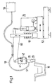
- FIG. 1 shows a vessel 10 on which a coupling part 20 is provided.
- the coupling part 20 is connected to a further coupling part 30 which is connected to a power supply system 55 via a power cable 51 of the power supply 50.
- the coupling part 30 is also connected to a compensating element 40 which is arranged in a support element 60.
- the compensating element 40 here has a spring 41 and a damper 42 in a schematic representation.
- the support element 60 is designed as a support arm which can be moved in two planes in FIG. 1.
- a vertical bearing 61 is provided for vertical movement and a horizontal bearing 62 for horizontal movement.
- the vertical movement of the support arm 60 takes place via a drive 70.
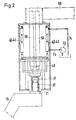
- a father part 21 is arranged on the vessel 10.
- the male part 21 is inserted into a female part 31, a current lamella 32 being arranged between the male part 21 and the female part 31.
- the nut part 31 is fastened to a balancer 48 of the compensating element 40, which in turn is connected to the support element 60 via a piston-cylinder unit 43.
- the mother part 31 is supplied with electrical energy via the power supply 50.
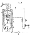
- the nut part 31 is arranged below the rim of the vessel 10.
- the schematic representation does not show the shape of the nut part 31 which tapers conically towards the mouth.
- the front area 26 of the male part 21 can be inserted into the female part 31.
- the father part 21 is tubular and has an axially displaceable rod 22 in the interior of the tube.
- the rod 22 is connected to a piston-cylinder unit 23, a spring 25 being provided between a piston 24 and the tubular father part 21.
- a feed line 77 leads to the piston-cylinder unit 23 into a feed line 76 provided with a pump 78.
- the piston-cylinder unit 23 is connected to the support element 60 via a piston-cylinder unit 43.
- the support element 60 has a protective sleeve 63 in its front region.
- the pump 72 is connected to a motor 70 via a control part 80.
- the motor 70 enables the support element 60 to be adjusted vertically.
- Vertical bearings 61 are provided for simple vertical guidance.
Landscapes
- Physics & Mathematics (AREA)
- Engineering & Computer Science (AREA)
- Plasma & Fusion (AREA)
- Furnace Details (AREA)
- Discharge Heating (AREA)
- Treatment Of Steel In Its Molten State (AREA)
- Reciprocating Pumps (AREA)
Description
- Die Erfindung betrifft eine Vorrichtung zum Kuppeln der an einer Stromversorgungsanlage angeschlossenen flexiblen Stromzuführung mit einer in einem metallurgischen Gefäß angeordneten Bodenelektrode.
- In der Hüttenindustrie kommen metallurgische Gefäße zum Einsatz, die mittels Gleichstrom beheizt werden. Dabei ragt regelmäßig die Kathode in das Gefäß hinein, und die Annode ist am Gefäßboden angeordnet.
- Die Anode kann dabei als Einzelelektrode, z.B. als metallische Stabelektrode ausgebildet sein. Es kann aber auch die Gefäßauskleidung elektrisch leitend sein, so daß das Gefäß oder ein Teil davon die Anode bilden und der Gefäßmantel zur Stromübertragung herangezogen wird.
- Bei einem Wechsel des metallurgischen Gefäßes oder bedingt durch den Verschleiß der Anode bei einem Wechsel der Anode ist die Stromzuführung an einem Anschlußstück zu lösen.
- So ist aus der EP-OS 0 133 931 eine Schraubverbindung bekannt. In nachteiliger Weise muß das Wartungspersonal unterhalb des Gefäßes manuell die Verbindung lösen.
- Aus der EP-OS 0 275 384 ist bekannt, als Kontakteinrichtung federbelastete Tragbolzen vorzusehen, die die Stromzuführleitung gegen die Elektrode pressen und die beim Lösen der elektrischen Kontakte zurückziehbar sind. Die Stromkabel sind dabei an verschiebbaren Laschen befestigt, die gelenkig gelagert sind.
- Bei dieser Kontaktvorrichtung wirken die vom Eigengewicht der Stromzuführungsleitung herrührenden Zugkräfte auf die Bodenelektrode. Außerdem ist kein Weg zur mechanisierten Heranführung des Stromzuführkabels vorgegeben.
- Aus der EP-A-0 178 981 ist eine Anschlußklemme für die Elektrode eines metallurgischen Gefäßes bekannt, bei der mittels teleskopischer Arme ein die Elektrode haltender Aufhängeflansch am Mantel des Gefäßes vorgesehenen Befestigungsflansch verbunden wird. Die in den Teleskoparmen angeordneten elastischen Elemente dienen zum Ausgleich der thermischen Längenänderung der Elektrode.
- Die Elektrode wird durch Druckkräfte belastet. Die Stromzuführung ist über einen Schraubflansch an dem herausragenden Teil der Elektrode befestigt und nur manuell lösbar.
- Eine hohe Betätigungsfrequenz der Kontaktvorrichtung tritt insbesondere auf bei Pfannenbehandlungsständen und bei Tundish-Beheizungsanlagen auf.
- Aus der EP-A-0 344 092 ist eine Einrichtung zur thermischen Behandlung von metallischem Schmelzgut bekannt, bei der zum Kuppeln der an einer Stromversorgungsanlage angeschlossenen flexiblen Stromzuführung mit einer in einem metallurgischen Gefäß angeordneten Bodenelektrode an dem metallurgischen Gefäß Kupplungsteile vorgesehen sind, die mit Kupplungsteilen kuppelbar sind, an denen mit einem Tragelement verbundene Ausgleichselemente angeordnet sind.
- Hier ist jedoch ein kraftfreies Führen des vorderen Bereiches der Stromzuführung nicht in hinreichendem Maße gegeben.
- Die Erfindung widmet sich dem Problem, eine Kontaktverbindung zwischen Elektrode und Stromversorgungsanlage zu schaffen, die bei einfachem Aufbau in einem weiten Bereich positionierbar ist, die ein mechanisiertes Kontaktieren zuläßt und deren Kontaktierung bei zuverlässiger Stromübertragung kraftneutral erfolgt.
- Die Erfindung löst dieses technische Problem gemäß der Merkmale des kennzeichnenden Teils des Hauptanspruches.
- Erfindungsgemäß wird der Teil der Kupplung, an dem die Stromzuführleitung angeschlossen ist, über Ausgleichselemente mit einem Tragarm verbunden. Der Tragarm ist bewegbar. Der bewegbar ausgebildete Tragarm dient zur Positionierung des an ihm befestigten zweiten Kupplungsteils mit dem am metallurgischen Gefäß angeordneten ersten Kupplungsteil.
- Es kommen Ausgleichselemente zum Einsatz, die nach erfolgter Kupplung der drei Kupplungsteile die Gewichtskräfte der flexiblen Stromzuführung kompensieren. Durch das Trennen von Kuppeln und Führen der Stromzuführleitung wird erfindungsgemäß die Elektrode und das metallurgische Gefäß von behindernden Zug- oder Druckkräften freigehalten.
- Als wartungsarme und funktionssichere Kupplung wird eine Hülsenkupplung vorgeschlagen, die im wesentlichen aus einem Vater- und einem Mutterteil besteht. Die Verbindung dieser Teile kann zur sicheren Stromübertragung kraft- und/oder formschlüssig erfolgen. So wird in einer Ausbildungsform ein Mutterteil mit einer sich zur Mündung hin verjüngenden konischen Form vorgeschlagen. In dieses Mutterteil ist ein Vaterteil einbringbar, das in seinem vorderen Bereich im Durchmesser radial vergrößerbar ist. Während des Betriebes sind beide Teile großflächig gegeneinander preßbar.
- In einer weiteren vorteilhaften Ausbildung sind zwischen dem Vater- und Mutterteil Stromlamellen angeordnet.
- Die Kupplungsteile, sei es bei einer Hülsenkupplung ein Vater- oder ein Mutterteil, lassen sich an dem metallurgischen Gefäß an beliebiger Stelle anordnen. Bei dem rauhen Hüttenbetrieb bietet sich eine vor Schmutz, Hitze und mechanischer Zerstörung geschützte Lage an. Dies wird vorzugsweise der Rand des Gefäßes sein, und zwar oberhalb - wie in der Zeichnung dargestellt - oder auch unterhalb des Bordes. Bei der genannten Alternative kann wiederum das Vaterteil oder das Mutterteil an dem Gefäß befestigt sein.
- Beim Einsatz von metallurgischen Gefäßen, die während des Betriebes einen Hub ausführen wie beispielsweise Verteilerrinnen o.ä., können steuerbare Ausgleichselemente zum Einsatz kommen. Diese Ausgleichselemente etwa in der Form von fluidbetriebenen Kolbenzylindern werden entsprechend der Erfindung so eingestellt, daß ein kraftfreies Führen im vollen Bereich des Hubes bezüglich Frequenz und Amplitude erfolgt.
- Ein Beispiel der Erfindung ist der Zeichnung aufgeführt. Es zeigen:
- Fig. 1 eine Kupplungsvorrichtung mit bewegbarem Tragarm,
- Fig. 2 Kupplung mit Ausgleichsvorrichtung,
- Fig. 3 Hülsenkupplung mit klemmbarem Vaterteil.
- Die Fig. 1 zeigt ein Gefäß 10, an dem ein Kupplungsteil 20 vorgesehen ist. Das Kupplungsteil 20 steht mit einem weiteren Kupplungsteil 30 in Verbindung, das über ein Stromkabel 51 der Stromzuführung 50 an eine Stromversorgungsanlage 55 angeschlossen ist.
- Das Kupplungsteil 30 ist darüber hinaus mit einem Ausgleichselement 40 verbunden, das einem Tragelement 60 angeordnet ist. Das Ausgleichselement 40 weist hier in schematischer Darstellung eine Feder 41 und einen Dämpfer 42 auf.
- Das Tragelement 60 ist als Tragarm ausgebildet, der in der Fig. 1 in zwei Ebenen bewegbar ist. Zur vertikalen Bewegung ist ein Vertikallager 61 und zur horizontalen ein Horizontallager 62 vorgesehen. Die vertikale Bewegung des Tragarms 60 erfolgt über einen Antrieb 70.
- In Fig. 2 ist am Gefäß 10 ein Vaterteil 21 angeordnet. Das Vaterteil 21 ist in ein Mutterteil 31 eingeführt, wobei zwischen dem Vaterteil 21 und dem Mutterteil 31 eine Stromlamelle 32 angeordnet ist. Das Mutterteil 31 ist an einem Balancier 48 des Ausgleichselementes 40 befestigt, das wiederum über eine Kolben-Zylinder-Einheit 43 mit dem Tragelement 60 in Verbindung steht.
- Zu der Kolben-Zylinder-Einheit 43 führen eine Hauptleitung 74 und eine mit einer Pumpe 72 verbundene Zuleitung 73.
- Die Versorgung des Mutterteils 31 mit elektrischer Energie erfolgt über die Stromzuführung 50.
- Bei der Fig. 3 ist das Mutterteil 31 unterhalb des Bordes des Gefäßes 10 angeordnet. Bei der schematischen Darstellung ist die sich zur Mündung hin konisch verjüngende Form des Mutterteils 31 nicht dargestellt. Der vordere Bereich 26 des Vaterteils 21 ist in das Mutterteil 31 einführbar. Das Vaterteil 21 ist rohrförmig ausgebildet und weist im Inneren des Rohres eine axial verschiebbare Stange 22 auf. Die Stange 22 ist mit einer Kolben-Zylinder-Einheit 23 verbunden, wobei zwischen einem Kolben 24 und dem rohrförmigen Vaterteil 21 eine Feder 25 vorgesehen ist. Zur Kolben-Zylinder-Einheit 23 führt eine Zuleitung 77 in eine mit einer Pumpe 78 versehene Zuleitung 76.
- Die Kolben-Zylinder-Einheit 23 ist über eine Kolben-Zylinder-Einheit 43 mit dem Tragelement 60 verbunden. Das Tragelement 60 weist in seinem vorderen Bereich eine Schutzhülse 63 auf.
- Zur Kolben-Zylinder-Einheit 43 führen Ableitungen 74 und mit einer Pumpe 72 in Verbindung stehende Zuleitungen 73.
- Die Pumpe 72 ist regeltechnisch über ein Steuerteil 80 mit einem Motor 70 verbunden. Der Motor 70 ermöglicht das vertikale Verstellen des Tragelementes 60. Zur einfachen vertikalen Führung sind Vertikallager 61 vorgesehen.
Claims (16)
- Vorrichtung zum Kuppeln der an einer Stromversorgungsanlage (55) angeschlossenen flexiblen Stromzuführung (50) mit einer in einem metallurgischen Gefäß (10) angeordneten Bodenelektrode, wobei an dem metallurgischen Gefäß (10) erste Kupplungsteile (20) vorhanden sind, und wobei die Vorrichtung mit den ersten Kupplungsteilen (20) kuppelbare zweite Kupplungsteile (30) und an denen angeordnete Ausgleichselemente (40) aufweist, die mit einem Tragelement (60) verbunden sind,
dadurch gekennzeichnet,
daß das Tragelement (60) als Arm ausgebildet ein Lager (61) zur vertikalen Bewegung aufweist, wobei zur vertikalen Bewegung des Tragarms (60) ein Antrieb (70) vorhanden ist und daß die Ausgleichselemente (40) derart angeordnet sind, daß sie ein kraftfreies Führen des den Kupplungsteilen (20, 30) benachbarten vorderen Bereichs (51) der flexiblen Stromzuführung (50) ermöglichen. - Vorrichtung nach Anspruch 1,
dadurch gekennzeichnet,
daß die Ausgleichselemente (40) Federn (41) sind. - Vorrichtung nach Anspruch 2,
dadurch gekennzeichnet,
daß parallel zu den Federn (41) Dämpfer (42) vorgesehen sind. - Vorrichtung nach Anspruch 1,
dadurch gekennzeichnet,
daß die Ausgleichselemente (40) mit einem Fluid verstellbare Zylinder-Kolben-Einheiten (43) sind. - Vorrichtung nach Anspruch 4,
dadurch gekennzeichnet,
daß die Zylinder-Kolben-Einheiten (43) über Zu- und Ableitungen (73, 74) mit einer Pumpe (72) verbunden sind. - Vorrichtung nach Anspruch 1 und 4,
dadurch gekennzeichnet,
daß der zur vertikalen Bewegung des Tragarmes (60) vorgesehene Antrieb (70) steuerungsmäßig (80) mit der Kolbenzylindereinheit (43) verbunden ist. - Vorrichtung nach Anspruch 1 und 6,
dadurch gekennzeichnet,
daß der Tragarm (60) zusätzlich zum vertikalen Lager (61) ein Lager (62) zur horizontalen Bewegung aufweist. - Vorrichtung nach Anspruch 1,
dadurch gekennzeichnet,
daß die Kupplungsteile (20, 30) eine Hülsenkupplung bilden. - Vorrichtung nach Anspruch 8,
dadurch gekennzeichnet,
daß ein Vaterteil (21) des ersten Kupplungsteils (20) am metallurgischen Gefäß (10) angeordnet ist und eine konische Außenform aufweist, die mit dem mit dem Tragarm (60) in Verbindung stehenden Mutterteil (31) des zweiten Kupplungsteils (30) korrespondiert. - Vorrichtung nach Anspruch 9,
dadurch gekennzeichnet,
daß das Mutterteil (31) an einem als Balancier ausgestalteten Träger (48) befestigt ist, der an dem Ausgleichselement (40) winkelbeweglich angeordnet ist. - Vorrichtung nach Anspruch 8,
dadurch gekennzeichnet,
daß das Vaterteil (21) der Hülsenkupplung (20, 30) mit dem Tragelement (60) in Verbindung steht und eine in Achsrichtung bewegbare Stange (22) aufweist, die eine Radialveränderung des vorderen Bereichs (26) des Vaterteils (21) ermöglicht. - Vorrichtung nach Anspruch 11,
dadurch gekennzeichnet,
daß der vordere Bereich (26) des Vaterteils (21) in die an dem metallurgischen Gefäß angeordnete Hülse des Mutterteils (31) einbringbar ist, die eine zur Mündung sich verjüngende konische Gestalt aufweist. - Vorrichtung nach Anspruch 11,
dadurch gekennzeichnet,
daß das Vaterteil (21) und die Stange (22) als Kolben-Zylinder-Einheit (23) ausgebildet sind. - Vorrichtung nach Anspruch 13,
dadurch gekennzeichnet,
daß zwischen einem Kolben (24) der Kolben-Zylinder-Einheit (23) und dem Vaterteil (21) eine Feder (25) angeordnet ist. - Vorrichtung nach Anspruch 14,
dadurch gekennzeichnet,
daß an der Kolben-Zylinder-Einheit (23) eine über Zu- und Ableitungen (76, 77) verbundene Pumpe (78) vorgesehen ist. - Vorrichtung nach Anspruch 8,
dadurch gekennzeichnet,
daß an der Hülsenkupplung zwischen den Kupplungsteilen (20, 30) eine Stromlamelle (32) vorgesehen ist.
Applications Claiming Priority (2)
| Application Number | Priority Date | Filing Date | Title |
|---|---|---|---|
| DE4108583 | 1991-03-14 | ||
| DE4108583A DE4108583C2 (de) | 1991-03-14 | 1991-03-14 | Vorrichtung zum Kuppeln der Stromzuführung zu einem metallurgischen Gefäß |
Publications (3)
| Publication Number | Publication Date |
|---|---|
| EP0512657A2 EP0512657A2 (de) | 1992-11-11 |
| EP0512657A3 EP0512657A3 (en) | 1993-02-17 |
| EP0512657B1 true EP0512657B1 (de) | 1995-04-05 |
Family
ID=6427454
Family Applications (1)
| Application Number | Title | Priority Date | Filing Date |
|---|---|---|---|
| EP92250030A Expired - Lifetime EP0512657B1 (de) | 1991-03-14 | 1992-02-13 | Vorrichtung zum Kuppeln der Stromzuführung zu einem metallurgischen Gefäss |
Country Status (6)
| Country | Link |
|---|---|
| US (1) | US5292109A (de) |
| EP (1) | EP0512657B1 (de) |
| JP (1) | JPH05129079A (de) |
| KR (1) | KR920019212A (de) |
| AT (1) | ATE120923T1 (de) |
| DE (2) | DE4108583C2 (de) |
Families Citing this family (2)
| Publication number | Priority date | Publication date | Assignee | Title |
|---|---|---|---|---|
| US20140321496A1 (en) * | 2011-12-23 | 2014-10-30 | Sms Mevac Gmbh | Device for supplying energy to melting furnaces |
| USD743712S1 (en) | 2013-03-15 | 2015-11-24 | Herman Miller, Inc. | Chair |
Family Cites Families (10)
| Publication number | Priority date | Publication date | Assignee | Title |
|---|---|---|---|---|
| US3198869A (en) * | 1962-03-28 | 1965-08-03 | Beteiligungs & Patentverw Gmbh | Current-feeding to the electrodes of an electric arc furnace |
| JPS6011433B2 (ja) * | 1978-03-01 | 1985-03-26 | 三菱電機株式会社 | 誘導加熱装置の給電ケ−ブル支持装置 |
| NO802266L (no) * | 1980-07-25 | 1982-01-26 | Elkem Spigerverket As | Koblingsorgan, saerlig egnet for bruk i forbindelse med elektrotermiske ovner. |
| ATE24815T1 (de) * | 1983-07-28 | 1987-01-15 | Bbc Brown Boveri & Cie | Kuehlanordnung einer bodenelektrode fuer einen gleichstromlichtbogenofen. |
| DE3419681A1 (de) * | 1984-05-24 | 1985-11-28 | Mannesmann AG, 4000 Düsseldorf | Gleichstrom-lichtbogen-heizvorrichtung |
| FR2571202B1 (fr) * | 1984-10-01 | 1987-01-09 | Usinor | Structure d'electrode pour bain de metal en fusion |
| US4682341A (en) * | 1984-11-29 | 1987-07-21 | Fuchs Systemtechnik Gmbh | Electric arc furnace |
| FR2577311B1 (fr) * | 1985-02-11 | 1987-03-06 | Siderurgie Fse Inst Rech | Dispositif de connexion electrique destine a etre place en paroi d'un four metallurgique a courant continu. |
| DE3701678A1 (de) * | 1987-01-22 | 1988-08-04 | Gutehoffnungshuette Man | Metallurgisches gefaess, insbesondere elektroofen mit einer oder mehreren bodenelektroden |
| DE3817379C1 (de) * | 1988-05-18 | 1989-06-22 | Mannesmann Ag, 4000 Duesseldorf, De |
-
1991
- 1991-03-14 DE DE4108583A patent/DE4108583C2/de not_active Expired - Fee Related
-
1992
- 1992-02-13 DE DE59201807T patent/DE59201807D1/de not_active Expired - Fee Related
- 1992-02-13 EP EP92250030A patent/EP0512657B1/de not_active Expired - Lifetime
- 1992-02-13 AT AT92250030T patent/ATE120923T1/de not_active IP Right Cessation
- 1992-03-06 KR KR1019920003737A patent/KR920019212A/ko not_active Abandoned
- 1992-03-11 JP JP4087775A patent/JPH05129079A/ja active Pending
- 1992-03-13 US US07/851,014 patent/US5292109A/en not_active Expired - Fee Related
Also Published As
| Publication number | Publication date |
|---|---|
| DE4108583C2 (de) | 1997-06-05 |
| US5292109A (en) | 1994-03-08 |
| DE59201807D1 (de) | 1995-05-11 |
| EP0512657A3 (en) | 1993-02-17 |
| ATE120923T1 (de) | 1995-04-15 |
| DE4108583A1 (de) | 1992-09-17 |
| KR920019212A (ko) | 1992-10-22 |
| JPH05129079A (ja) | 1993-05-25 |
| EP0512657A2 (de) | 1992-11-11 |
Similar Documents
| Publication | Publication Date | Title |
|---|---|---|
| DE3152716C2 (de) | Zweipoliges Anschlussst}ck f}r ein wassergek}hltesHochstromkabel | |
| EP0061612A1 (de) | Hochstromleitungssystem für Elektroöfen | |
| EP3075208B1 (de) | Vorrichtung und verfahren zum nachsetzen einer elektrode für einen metallurgischen ofen | |
| CH677046A5 (de) | ||
| DE2626071C2 (de) | ||
| DE4108583C2 (de) | Vorrichtung zum Kuppeln der Stromzuführung zu einem metallurgischen Gefäß | |
| CH671453A5 (de) | ||
| DE3304099C2 (de) | ||
| EP0134525A1 (de) | Elektrische Hochspannungsdurchführung für ein in einem Gehäuse eingeschlossenes elektrisches Gerät | |
| EP0275384B1 (de) | Metallurgisches Gefäss, insbesondere Elektroofen mit einer oder mehreren Bodenelektroden | |
| DE3342900A1 (de) | Elektrodenfassungssystem fuer elektrothermische schmelzoefen | |
| DE3817379C1 (de) | ||
| DE868643C (de) | Klemmanordnung fuer Elektroden an Lichtbogenoefen | |
| EP1287723B1 (de) | Verfahren und einrichtung zum wechseln der elektroden an einem elektrisch betriebenen metallurgischen gefäss, insbesondere an einem lichtbogenofen | |
| EP0221270B1 (de) | Kontaktverbindung für die Kontaktelektrode eines Lichtbogen- oder Widerstands-Schmelzofens | |
| EP0071107A1 (de) | Vorrichtung zum Annippeln einer Graphitelektrode an eine Dauerelektrode eines Elektroofens | |
| DE1293360B (de) | Einrichtung zur Halterung und Stromversorgung einer Abschmelzelektrode in einem Lichtbogenofen | |
| EP0120312B1 (de) | Nachsetz- und Haltevorrichtung für eine Elektrode eines Lichtbogenofens | |
| DE102018103312B4 (de) | Umschmelzanlage und Verfahren zum Betrieb einer Umschmelzanlage | |
| DE955525C (de) | Elektromotor mit mechanischer Kupplung und Bremse | |
| DE3016087A1 (de) | Mittels gleichstrom oder wechselstrom ueber hochstromleiter gepeister elektroofen | |
| DE898212C (de) | Korpuskularstrahlapparat | |
| EP0505902A1 (de) | Abdichtelement für mit Kabeln belegte Kabelzüge in Kabelkanälen | |
| DE2055581A1 (de) | Spannvorrichtung an Elektrodenfassun gen an elektrischen Schmelzofen | |
| DE891586C (de) | Vorrichtung zur UEbertragung von Vorschubbewegungen von aussen in das Innere von elektrischen Entladungsgefaessen, vorzugsweise Elektronenmikroskopen |
Legal Events
| Date | Code | Title | Description |
|---|---|---|---|
| PUAI | Public reference made under article 153(3) epc to a published international application that has entered the european phase |
Free format text: ORIGINAL CODE: 0009012 |
|
| AK | Designated contracting states |
Kind code of ref document: A2 Designated state(s): AT CH DE GB IT LI SE |
|
| PUAL | Search report despatched |
Free format text: ORIGINAL CODE: 0009013 |
|
| AK | Designated contracting states |
Kind code of ref document: A3 Designated state(s): AT CH DE GB IT LI SE |
|
| 17P | Request for examination filed |
Effective date: 19930510 |
|
| 17Q | First examination report despatched |
Effective date: 19930816 |
|
| GRAA | (expected) grant |
Free format text: ORIGINAL CODE: 0009210 |
|
| AK | Designated contracting states |
Kind code of ref document: B1 Designated state(s): AT CH DE GB IT LI SE |
|
| PG25 | Lapsed in a contracting state [announced via postgrant information from national office to epo] |
Ref country code: IT Free format text: LAPSE BECAUSE OF FAILURE TO SUBMIT A TRANSLATION OF THE DESCRIPTION OR TO PAY THE FEE WITHIN THE PRE;WARNING: LAPSES OF ITALIAN PATENTS WITH EFFECTIVE DATE BEFORE 2007 MAY HAVE OCCURRED AT ANY TIME BEFORE 2007. THE CORRECT EFFECTIVE DATE MAY BE DIFFERENT FROM THE ONE RECORDED.SCRIBED TIME-LIMIT Effective date: 19950405 |
|
| REF | Corresponds to: |
Ref document number: 120923 Country of ref document: AT Date of ref document: 19950415 Kind code of ref document: T |
|
| REF | Corresponds to: |
Ref document number: 59201807 Country of ref document: DE Date of ref document: 19950511 |
|
| GBT | Gb: translation of ep patent filed (gb section 77(6)(a)/1977) |
Effective date: 19950612 |
|
| PLBE | No opposition filed within time limit |
Free format text: ORIGINAL CODE: 0009261 |
|
| 26N | No opposition filed | ||
| REG | Reference to a national code |
Ref country code: GB Ref legal event code: IF02 |
|
| PGFP | Annual fee paid to national office [announced via postgrant information from national office to epo] |
Ref country code: CH Payment date: 20030121 Year of fee payment: 12 |
|
| PGFP | Annual fee paid to national office [announced via postgrant information from national office to epo] |
Ref country code: GB Payment date: 20030130 Year of fee payment: 12 |
|
| PGFP | Annual fee paid to national office [announced via postgrant information from national office to epo] |
Ref country code: SE Payment date: 20030204 Year of fee payment: 12 |
|
| PGFP | Annual fee paid to national office [announced via postgrant information from national office to epo] |
Ref country code: AT Payment date: 20030205 Year of fee payment: 12 |
|
| PGFP | Annual fee paid to national office [announced via postgrant information from national office to epo] |
Ref country code: DE Payment date: 20030208 Year of fee payment: 12 |
|
| PG25 | Lapsed in a contracting state [announced via postgrant information from national office to epo] |
Ref country code: AT Free format text: LAPSE BECAUSE OF NON-PAYMENT OF DUE FEES Effective date: 20040213 Ref country code: GB Free format text: LAPSE BECAUSE OF NON-PAYMENT OF DUE FEES Effective date: 20040213 |
|
| PG25 | Lapsed in a contracting state [announced via postgrant information from national office to epo] |
Ref country code: SE Free format text: LAPSE BECAUSE OF NON-PAYMENT OF DUE FEES Effective date: 20040214 |
|
| PG25 | Lapsed in a contracting state [announced via postgrant information from national office to epo] |
Ref country code: CH Free format text: LAPSE BECAUSE OF NON-PAYMENT OF DUE FEES Effective date: 20040229 Ref country code: LI Free format text: LAPSE BECAUSE OF NON-PAYMENT OF DUE FEES Effective date: 20040229 |
|
| PG25 | Lapsed in a contracting state [announced via postgrant information from national office to epo] |
Ref country code: DE Free format text: LAPSE BECAUSE OF NON-PAYMENT OF DUE FEES Effective date: 20040901 |
|
| EUG | Se: european patent has lapsed | ||
| GBPC | Gb: european patent ceased through non-payment of renewal fee |
Effective date: 20040213 |
|
| REG | Reference to a national code |
Ref country code: CH Ref legal event code: PL |