EP0510975B1 - Effiziente Kodierungs- und Dekodierungsanordnungen zur Verarbeitung eines digitalen Bildsignals - Google Patents
Effiziente Kodierungs- und Dekodierungsanordnungen zur Verarbeitung eines digitalen Bildsignals Download PDFInfo
- Publication number
- EP0510975B1 EP0510975B1 EP19920303663 EP92303663A EP0510975B1 EP 0510975 B1 EP0510975 B1 EP 0510975B1 EP 19920303663 EP19920303663 EP 19920303663 EP 92303663 A EP92303663 A EP 92303663A EP 0510975 B1 EP0510975 B1 EP 0510975B1
- Authority
- EP
- European Patent Office
- Prior art keywords
- signal
- image signal
- frame
- coding
- motion
- Prior art date
- Legal status (The legal status is an assumption and is not a legal conclusion. Google has not performed a legal analysis and makes no representation as to the accuracy of the status listed.)
- Expired - Lifetime
Links
Images


Classifications
-
- H—ELECTRICITY
- H04—ELECTRIC COMMUNICATION TECHNIQUE
- H04N—PICTORIAL COMMUNICATION, e.g. TELEVISION
- H04N5/00—Details of television systems
- H04N5/76—Television signal recording
- H04N5/91—Television signal processing therefor
- H04N5/92—Transformation of the television signal for recording, e.g. modulation, frequency changing; Inverse transformation for playback
- H04N5/926—Transformation of the television signal for recording, e.g. modulation, frequency changing; Inverse transformation for playback by pulse code modulation
- H04N5/9261—Transformation of the television signal for recording, e.g. modulation, frequency changing; Inverse transformation for playback by pulse code modulation involving data reduction
- H04N5/9264—Transformation of the television signal for recording, e.g. modulation, frequency changing; Inverse transformation for playback by pulse code modulation involving data reduction using transform coding
-
- H—ELECTRICITY
- H04—ELECTRIC COMMUNICATION TECHNIQUE
- H04N—PICTORIAL COMMUNICATION, e.g. TELEVISION
- H04N19/00—Methods or arrangements for coding, decoding, compressing or decompressing digital video signals
- H04N19/10—Methods or arrangements for coding, decoding, compressing or decompressing digital video signals using adaptive coding
- H04N19/102—Methods or arrangements for coding, decoding, compressing or decompressing digital video signals using adaptive coding characterised by the element, parameter or selection affected or controlled by the adaptive coding
- H04N19/103—Selection of coding mode or of prediction mode
- H04N19/112—Selection of coding mode or of prediction mode according to a given display mode, e.g. for interlaced or progressive display mode
-
- H—ELECTRICITY
- H04—ELECTRIC COMMUNICATION TECHNIQUE
- H04N—PICTORIAL COMMUNICATION, e.g. TELEVISION
- H04N19/00—Methods or arrangements for coding, decoding, compressing or decompressing digital video signals
- H04N19/50—Methods or arrangements for coding, decoding, compressing or decompressing digital video signals using predictive coding
- H04N19/503—Methods or arrangements for coding, decoding, compressing or decompressing digital video signals using predictive coding involving temporal prediction
-
- H—ELECTRICITY
- H04—ELECTRIC COMMUNICATION TECHNIQUE
- H04N—PICTORIAL COMMUNICATION, e.g. TELEVISION
- H04N19/00—Methods or arrangements for coding, decoding, compressing or decompressing digital video signals
- H04N19/60—Methods or arrangements for coding, decoding, compressing or decompressing digital video signals using transform coding
- H04N19/61—Methods or arrangements for coding, decoding, compressing or decompressing digital video signals using transform coding in combination with predictive coding
-
- H—ELECTRICITY
- H04—ELECTRIC COMMUNICATION TECHNIQUE
- H04N—PICTORIAL COMMUNICATION, e.g. TELEVISION
- H04N19/00—Methods or arrangements for coding, decoding, compressing or decompressing digital video signals
- H04N19/10—Methods or arrangements for coding, decoding, compressing or decompressing digital video signals using adaptive coding
- H04N19/102—Methods or arrangements for coding, decoding, compressing or decompressing digital video signals using adaptive coding characterised by the element, parameter or selection affected or controlled by the adaptive coding
- H04N19/124—Quantisation
- H04N19/126—Details of normalisation or weighting functions, e.g. normalisation matrices or variable uniform quantisers
-
- H—ELECTRICITY
- H04—ELECTRIC COMMUNICATION TECHNIQUE
- H04N—PICTORIAL COMMUNICATION, e.g. TELEVISION
- H04N19/00—Methods or arrangements for coding, decoding, compressing or decompressing digital video signals
- H04N19/60—Methods or arrangements for coding, decoding, compressing or decompressing digital video signals using transform coding
Definitions
- This invention relates to an efficient encoding apparatus adapted for efficiently encoding an image signal with a less quantity of codes and a decoding apparatus adapted for decoding such a coded signal in a processing system for recording, transmitting, and displaying a digital signal.
- a "predictive coding” technology and a “orthogonal transform” technology are known as a most popular technology in recent years, e.g. as shown in US-A-4 723 161.
- the "prediction coding” technology is used for the interframe processing
- the "orthogonal transform” technology is used for the intraframe processing.
- the interframe prediction there are many instances where a "motion compensation” to vary a predictive signal in correspondence with motion of a picture is carried out, and an orthogonally transformed and quantized predictive residual signal is replaced by a "variable length code”.
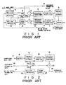
- FIG. 1 is a block diagram showing a conventional coding apparatus.
- an original image signal inputted from an image input terminal 1 is delivered to a subtracter 2 and a motion vector detector 3.
- the subtracter 2 subtracts a predictive signal which will be described later from the original image signal to provide a predictive residual to deliver it to an orthogonal transformer or transform element 4.
- the orthogonal transformer 4 orthogonally transforms this predictive residual every block consisting of 8x8 pixels or so by the Discrete Cosine Transform (DCT) technique, etc. to deliver it to a quantizer 5.
- the quantizer 5 quantizes an input signal with a suitable accuracy. Since most of input signals take a value originally nearly equal to zero, most of output signals from the quantizer 5 also take zero.
- An output signal from the quantizer 5 is delivered to a variable length encoder 6 and an inverse-quantizer 7.
- the variable length encoder 6 effect a processing such that when the input signal is equal zero, the encoder 6 converts the number of succession of signals to a variable length code such as a Huffman code, etc., and when the input signal takes a value except for zero, the encoder 6 converts that value to a variable length code, thereafter to deliver the variable length code thus obtained to a buffer 8 as compressed data.
- the rate of data outputted from the variable length encoder 6 is not fixed. Accordingly, that data is delivered to the buffer 8 so that it has a fixed rate.
- the data passed through the buffer 8 is outputted from a compressed data output terminal 9 to a decoding apparatus side.
- a predictive signal delivered to the subtracter 2 is a signal earlier by one frame.
- this predictive signal is processed as follows.
- the inverse-quantizer 7 inverse-quantizes a quantized signal which is an output signal of the quantizer 5 to replace it by a representative value of quantization to deliver it to an inverse orthogonal transformer 10.
- the inverse-orthogonal transformer 10 carries out an inverse transform processing of the orthogonal transformation to deliver its output signal to an adder 11.
- the adder 11 adds an output signal from the inverse orthogonal transformer 10 and a predictive signal delivered from a terminal 12c of a changeover switch 12 to provide the signal thus added as a reproduced image signal to deliver it to a frame memory 13.
- the frame memory 13 delays the reproduced image signal by one frame thereafter to deliver it to the motion vector detector 3 and a motion compensator 14.
- the motion vector detector 3 searches motion of an image every about 16 ⁇ 16 pixels between an original image signal from the image input terminal 1 and a signal earlier by one frame from the frame memory 13 to obtain most accurate information to transmit it to the decoding apparatus side through a motion vector information output terminal 15, and to deliver it also to the motion compensator 14.
- the motion compensator 14 implements a motion compensative processing to an output signal from the frame memory 13 in correspondence with a motion vector value delivered from the motion vector detector 3 to obtain a predictive signal to deliver it as a subtraction signal to the subtracter 2 through terminals 12b and 12c of the changeover switch 12.
- the changeover switch 12 serves to ensure a suitable interframe prediction. The operation of the changeover switch 12 will now be described.
- the motion vector detector 3 is adapted to output independent information for independently making coding without carrying out prediction in the case where a matching error between frames is large even if a motion vector is considered to be optimum to transmit such independent information to the decoding apparatus side through an independent information output terminal 16, and to deliver it also to the changeover switch 12.
- the changeover switch 12 is switched, by this independent information, not to the 12b side (output of the motion compensator 14), but to a fixed value (0) on the 12a side, thus to inhibit interframe prediction.
- FIG. 2 is a block diagram showing a conventional decoding apparatus.
- compressed data transmitted from the coding apparatus side shown in FIG. 1 is incoming through a compressed data input terminal 17 and a buffer 18, and is then delivered to a variable length decoder 19.
- the variable length decoder 19 converts a variable length code of the compressed data to a fixed length to deliver it to an inverse-quantizer 20.
- the inverse quantizer 20 inverse-quantizes an input signal to deliver it to an inverse orthogonal transformer 21.
- the inverse-orthogonal transformer 21 implements an inverse orthogonal transform processing to that input signal to obtain a predictive residual signal to deliver it to an adder 22.
- the adder 22 adds the reproduced predictive residual signal and a predictive signal delivered from a changeover switch 23 to obtain a reproduced image signal to output it through a reproduced image output terminal 24, and to deliver it also to a frame memory 25.
- the frame memory 25 delays the reproduced image signal by one frame thereafter to deliver it to a motion compensator 26.
- the motion compensator 26 carries out motion compensation of the reproduced image signal by motion vector information transmitted from the coding apparatus side through a motion vector information input terminal 27 to obtain a predictive signal to deliver it as an addition signal to the adder 22 through terminals 23b and 23c of the changeover switch 23.
- the changeover switch 23 is switched, by independent information transmitted from the coding apparatus side through an independent input terminal 28, not to the 23b side (output of the motion compensator 26), but to the fixed value (0) on the 23a side, thus to inhibit interframe prediction.
- This invention has been made by drawing attention to the above-described problems, and its object is to provide efficient coding/decoding apparatuses adapted for independently coding respective frames within a frame to allow an error occurring between an original image signal and a coded reproduced image signal be exerted on other frames to carry out an addition between frames on the decoding side to lessen error signals so that respective frames can be independently handled, thereby making it possible to easily carry out, without degradation in picture quality, random access, high speed search or image editing necessary in media of the storage system, to provide a coding efficiency closer to that of the interframe predictive coding by reduction of an error, to improve efficiency to more degree rather than that in the predictive coding particularly in the case where a correlation between frames is low, to provide a reproduced image desirable from a visual point of view, and to employ a simple construction.
- this invention provides: a coding apparatus for use in coding processing utilizing correlation between frames or fields of an image signal, comprising:
- the coding apparatus further comprises:
- the present invention also provides a decoding apparatus for decoding an encoded image signal of the type output by encoding apparatus as defined above, the decoding apparatus comprising:
- the decoding apparatus comprises;
- a scheme is employed to independently carry out coding within respective frames to allow errors between an original image and a coded reproduced image, which takes place by quantization error, to be exerted on other frames, and to cancel such errors by additive processing between frames on the decoding side.
- the values of the coefficients Ke and Kd are changed depending upon degree of matching of respective images. Namely, in the case where correlation is high and respective images match with each other to much degree, those values are caused to be large. In contrast, in the case where correlation is low and respective images match with each other to less degree, those values are caused to be small.
- motion compensation is carried out in the same manner as in the case of the interframe prediction.
- the efficiency is improved to more degree than that in the case where coding is independently carried out even at the portion where interframe correlation of an image is relatively low. For this reason, in such a case, the efficiency becomes higher than that of the interframe predictive coding.
- the degree of changes of a data quantity, which takes place by the property of an image becomes small.
- an approach is employed to independently encode respective frames within a frame to allow respective errors occurring between original image signal and corresponding coded reproduced image signal to be exerted on other frames to carry out an addition between frames on the decoding side to lessen error signals so that respective frames can be independently handled, thereby making it possible to easily carry out, without degradation in picture quality, random access, high speed search or image editing necessary in media of the storage system, to provide a coding efficiency closer to that of the interframe predictive coding by reduction of an error, to improve efficiency to more degree rather than that in the predictive coding particularly in the case where a correlation between frames is low, to provide a reproduced image desirable from a visual point of view, and to employ a simple construction.
- FIG. 3 is a block diagram showing a first embodiment of an efficient coding apparatus according to this invention wherein the same reference numerals are respectively attached to the same portions as those in FIG. 1, and their explanation will be omitted.
- an original image signal inputted from an image input terminal 1 is delivered to an adder 30, a motion vector detector 31, and a frame memory 32.
- the adder 30 adds a negative error signal which will be described later to the original image signal to deliver an added signal to orthogonal transformer 4 and a subtracter 33.
- the operation at the orthogonal transform element 4 and components succeeding thereto is essentially the same as that in the prior art.
- the interframe prediction of the prior art is the processing for a predictive residual, whereas, in this embodiment, such interframe prediction is the processing substantially for an original image signal because an error signal is small although a negative error signal is added thereto.
- the quantization step, and the variable length coding, etc. somewhat differ from those of the prior art, and basically becomes equivalent to the case where coding is independently carried out within a frame.
- a quantized signal is delivered to an inverse-quantizer 7 in the same manner as in the prior art.
- a reproduced image signal is provided by the inverse-quantizer 7 and an inverse orthogonal transformer 10.
- An output signal of the inverse orthogonal transformer 10 was a reproduced image signal of a predictive residual in the prior art, but is a reproduced image signal of an original image in this embodiment.
- a subtracter 33 subtracts an output signal of the inverse orthogonal transformer 10 from an output signal of the adder 30 to obtain a negative error signal occurring in the intraframe coding/decoding processing to deliver it to frame memory 13.
- the frame memory 13 delays the negative error signal by one frame to deliver it to motion compensator 14.
- the amplitude of the negative error signal is extremely smaller than that of the original image signal, when the amplitude of the negative error signal is limited before that signal is inputted to the frame memory 13, the number of bits of the frame memory can be reduced. If the original image signal is 8 bits (i.e., 0 ⁇ 255) as an example, the number of bits of the frame memory can be reduced to 4 bits (-7 ⁇ +7). Thus, the capacity of the frame memory 13 can be one half.
- the motion compensator 14 implements motion compensation processing to an output signal of the frame memory 13 in correspondence with a motion vector value delivered from the motion vector detector 31 to obtain a motion compensated negative error signal to deliver it to a multiplier 34.
- the motion vector detector 31 outputs matching information to deliver it to the decoding apparatus side through a matching information output terminal 35, and to deliver it to a quantizer 36 and the multiplier 34.
- the motion vector detector 31 carries out the above-mentioned operation.
- the quantizer 36 becomes operative to allow the quantization step to be fine to improve the picture quality so that the entirety thereof is well-balanced.
- the portion where matching is bad is the portion where an image abruptly changes, and degradation in the picture quality is difficult to be visually conspicuous. Accordingly, it is unnecessary to entirely implement improvement of the picture quality by additive processing between frames.
- the degree of matching is determined by taking absolute values of differences between corresponding pixels of two images and averaging the absolute values.
- setting is made such that the quantization step is caused to be fine relatively by about l5% every time the average value of the absolute values increments by 2 from zero, and is caused to be the same when the average value of absolute values is more than 6.
- the multiplier 34 multiplies the motion compensated negative error signal by the coefficient Ke (0 ⁇ 1) determined by information indicative of the degree of matching of an optimum motion vectors outputted from the motion vector detector 31 to deliver it to the adder 30.
- the motion vector detector 31 since the average of absolute values of pixel differences between two images is calculated in order to determine a motion vector, the motion vector detector 31 is only required to output, every block, an optimum vector corresponding to a minimum value. Accordingly, supplement of processing is not required in particular.
- the motion vector detector 31 searches, every about l6 x 16 pixels, motion of an image between an original image signal from the image input terminal 1 and a signal earlier by one frame from the frame memory 32 to obtain most accurate motion vector information to deliver it to the decoding apparatus side through the motion vector information output terminal 15, and also to the motion compensator 14.
- an image signal in which an error signal of a last frame is subtracted at the portion where correlation of images is high is subjected to intraframe coding by the processing succeeding to the orthogonal transform processing.
- FIG. 4 is a block diagram showing an embodiment of an efficient decoding apparatus wherein the same reference numerals are respectively attached to the same portions as those in FIG. 2, and their explanation will be omitted.
- the inverse orthogonal transformer 21 implements an inverse orthogonal transform processing to an input signal to obtain a reproduced image signal to deliver it to a subtracter 37.
- the subtracter 37 subtracts the reproduced image signal which is an output signal of the inverse orthogonal transformer 21 from a motion compensated reproduced image signal of a last frame outputted from the motion compensator 26 to deliver it to a non-linear converter 38.
- matching information transmitted from the coding apparatus through a matching information input terminal 39 is delivered to the non-linear converter 38 and an inverse quantizer 40.
- the non-linear converter 38 is controlled by matching information to implement non-linear conversion to an input signal to deliver it to an adder 41.
- the adder 41 adds the reproduced image signal which is an output signal of the inverse orthogonal transformer 21 and an output signal of the non-linear converter 38 to output it as a reproduced image signal through reproduced image output terminal 24, and to deliver it also to frame memory 25.
- the frame memory 25 delays the reproduced image signal by one frame thereafter to deliver it to motion compensator 26.
- the motion compensator 26 implements motion compensation processing to a reproduced image signal of a last frame by motion vector information transmitted from the coding apparatus side through the motion vector information input terminal 27 to obtain a motion compensated reproduced image signal of a last frame to deliver it to the subtracter 37.
- the subtracter 37, the non-linear converter 38 and the adder 41 are provided for multiplying an original image signal by (l-Kd), and for multiplying a signal earlier by one frame by Kd to add them.
- the coefficient multiplied at the non-linear converter 38 is Kd.
- Kd is equal to zero, i.e., an output signal of the non-linear converter 38 is equal to zero, an original image signal is outputted as it is.
- Kd is equal to 1
- an output signal of the non-linear converter 38 is the same as an input signal
- the original image signal is canceled by subtraction and addition, so a signal earlier by one frame is provided as an output signal as it is.
- the coefficient Kd will vary by an input signal of the non-linear converter, i.e., an interframe difference signal in correspondence with the non-linear conversion characteristic.
- FIG. 5 is a diagram showing an example of the characteristic of the non-linear conversion wherein the abscissa and the ordinate represent an input and an output, respectively.
- the coefficient is represented by Ke in the case of the coding apparatus
- the coefficient is represented by Kd in the case of the decoding apparatus.
- the coefficient Ke (Kd) is equal to a value close to 1.
- the coefficient Ke (Kd) becomes small.
- the coefficient Ke (Kd) becomes equal to zero.
- the conversion characteristic is varied by matching information in correspondence with changes in the quantization step. Namely, in the case where matching is bad, so quantization step is fine (a side in FIG. 5), the coefficient Ke (Kd) is caused to be immediately small.
- FIG. 7 is a diagram showing coding efficiencies in the technique of this invention and the conventional predictive processing wherein the abscissa and the ordinate represent an image correlation and a quantity of data generated.
- the technique of the invention is inferior to the predictive processing.
- FIG. 6 is a block diagram showing a second embodiment of an efficient coding apparatus according to this invention wherein the same reference numerals are respectively attached to the same portions as those of FIGS. 1 and 3, and their explanation will be omitted.
- the major difference between the coding apparatus of this embodiment and the coding apparatus of FIG. 3 is as follows. Namely, in FIG. 3, only a negative error signal (coded error) is used for feedback. In contrast, in FIG. 6, signal component including a negative error signal, i.e., a signal in which a negative error signal is added to an original image signal is used. Thus, it is sufficient to use a single frame memory, and addition of errors can be carried out every pixel.
- an original image signal inputted from image input terminal 1 is delivered to adder 30, motion vector detector 3, and an activity detector 43.
- the adder 30 adds an output signal of the non-linear converter 38 which will be described later to the original image signal to deliver it to orthogonal transformer 4 and a doubler 44.
- An output signal of the inverse orthogonal transform element 4 serves as a reproduced image signal of an original image, i.e., (original image signal + error signal).
- the doubler 44 amplifies an output signal of the adder 30 so that it becomes double to deliver it to subtracter 33.
- the subtracter 33 subtracts an output signal of the inverse orthogonal transformer 10 from an output signal of the doubler 44, i.e., carries out an operation of 2 ⁇ original image signal - (original image signal + error signal) to obtain a signal component including a negative error signal, i.e., (original image signal + error signal) to deliver it to the frame memory 13.
- the frame memory 13 delays an input signal by one frame thereafter to deliver it to motion compensator 14 and motion vector detector 3.
- the motion vector detector 3 searches, every about 16 ⁇ 16 pixels, motion of an image between an original image signal from the image input terminal 1 and (original image signal - error signal) earlier by one frame from the frame memory 13 to obtain the likeliest motion vector information to deliver it to the decoding apparatus side through the motion vector information output terminal 15, and to deliver it also to the motion compensator 14.
- the motion compensator 14 implements motion compensation processing to an output signal of the frame memory 13 in correspondence with a motion vector value delivered from the motion vector detector 3 to obtain a motion-compensated (original image signal - error signal) earlier by one frame to deliver it to subtracter 45.
- the subtracter 45 subtracts the original image signal inputted from the image input terminal 1 from the motion-compensated (original image signal - error signal) earlier by one frame to deliver it to the non-linear converter 38.
- the activity detector 43 detects or determines an activity of an image every orthogonal transform block or motion compensation block to deliver it to a quantization step setter 46.
- the quantization step setter 46 is controlled by two parameters of information of a quantity of data delivered from the buffer 8 and activity to obtain information of the quantization step to deliver it to the decoding apparatus side through quantization step information output terminal 47, and to deliver it also to the nonlinear converter 38 and the quantizer 36.
- the operation of the quantization step setter 46 is as follows. Namely, in the case where a quantity of data stored in the buffer is great, since it is necessary to reduce a quantity of data generated, the quantization step is caused to be coarse. Further, since degradation is difficult to be visually conspicuous at portions where the activity is high of respective blocks, the quantization step is caused to be coarse.
- the operations of the subtracter 45, the non-linear converter 38 and the adder 30 are the same as those of the subtracter 37, the non-linear converter and the adder 4l in the decoding apparatus shown in FIG. 4. Namely, original image signal and (original image signal - error signal) earlier by one frame are compared with each other. As a result, in the case where a difference therebetween is small, the (original image signal - error signal) earlier by one frame results in a signal to be coded. In contrast, in the case where that difference is large, the original image signal results in a signal to be coded.
- the non-linear converter 38 implements a non-linear conversion processing to an input signal in correspondence with a quantization step changing in dependency upon control of the data rate and the activity of an image to deliver it to the adder 30.
- the operation of the non-linear converter 38 is as follows. Namely, in the case where the quantization step is caused to be coarse, the range of an input value serving as a large coefficient Ke is widened. Thus, even if there is a difference to some extent, the time filter is caused to be effective to more degree (d side in FIG. 5). In contrast, in the case where the quantization step is fine, since an error produced by coding becomes small, the range of a difference signal subject to filtering is narrowed, thus allowing a change in an image not to be subjected to filtering (a side in FIG. 5).
- the quantizer 36 quantizes an input signal at a quantization step corresponding to quantization step information delivered from the quantization step setter 46.
- the decoding apparatus shown in FIG. 4 can be used as it is. This is because matching information in FIG. 3 may help to conduct control of the quantization step.
- FIGS. 3, 4 and 6 While the processing of FIGS. 3, 4 and 6 is directed to the processing between respective adjacent two frames, it is conceivable, in the same manner as in the conventional predictive processing, also in this technique to adopt various processing between fames, or between fields.
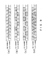
- FIGS. 8(a) to 8(c) are views for explaining processing every frame of a non-interlaced signal.
- squares represents respective frames, and arrows represent frame pairs from which errors therebetween are given.
- FIG. 8 (a) shows the basic case where each error between a frame and only a last frame (frame earlier only by one frame) is used.
- FIGS. 8(b) and 8(c) show processing proposed by the standardization of ISO/IEC. Namely, FIG. 8(b) shows a processing of the first stage where each error between frames jumping by several frames (three frames in the figure) is used.
- FIG. 8(b) shows a processing of the first stage where each error between frames jumping by several frames (three frames in the figure) is used.
- FIG. 8(c) shows a processing from frames of the first stage (frames indicated by slanting lines) with respect to frames caused to be jumped by the processing of the first stage. Since the processing of the second stage FIG. 8(c) is a processing from preceding and succeeding two frames, although a plurality of methods such as a method of using only the preceding frame, a method of using only the succeeding frame, and a method of using addition between preceding and succeeding frames, etc. are conceivable, alteration of the processing in that case is similar to alteration in the case of the predictive processing.
- FIGS. 9(a) to 9(d) are views for explaining the processing every field of an interlaced signal.
- squares represent respective fields, and arrows frame pairs from which errors therebetween are given. Because of the interlaced signal, there is a time shift of 1/2 frame between even fields and odd fields.
- FIG. 9 (a) shows the processing from a last frame and a last field, which is proposed by the standardization of CCIR/CCITT.
- FIGS. 9(b) and 9(c) show the processing expanded to the processing between fields wherein processing between fields jumping by three fields is carried out with respective even and odd fields. Namely, in the processing of FIG. 9(b), errors between even jumping fields, errors between odd jumping fields, and errors between even and odd fields are used. Further, in the processing of FIG. 9(c), errors between even and odd jumping fields and those preceding and succeeding thereto are used. It is to be noted that since if only fields earlier by three fields are used in FIG. 9(b), there result solely fields having an even and odd relationship opposite to that of a current field, it is suitable to use fields earlier by three frames, which are earlier further by three fields.
- FIG. 9(d) shows a processing obtained by developing the processing of FIG. 9(c) wherein three fields before and after are used. In this case, since fields having the same odd and even relationship are present before and after, it is possible to maintain correlation between images at a high level.
- FIGS. 8(a) to 8(c) are represented by curves outside the squares
- arrows in FIGS. 9(a) to 9(d) are represented by straight lines inside squares, such an indication is adopted for convenience of drawing figures. This is not particularly meaningful.
- the interframe processing system and the interfield processing system of this technique are similar to the predictive processing. Accordingly, processing which can be used in the predictive processing may be basically used in this invention. Further, in the case of a system of two stages, an approach may be employed such that the processing of the first stage is carried out by this technique and the processing of the second stage is by the predictive processing, and vice versa. Particularly, in the case of interlaced interframe processing, the interframe correlation is easy to be lower. Accordingly, this technique is advantageous.
Claims (7)
- Eine Kodierungsanordnung zur Verwendung bei der Kodierungsverarbeitung, wobei die Korrelation zwischen Rahmen oder Feldern eines Bildsignals verwendet wird, welche aufweist:welche dadurch gekennzeichnet ist,rahmeneigene oder feldeigene Kodierungseinrichtungen (4,36) zur Kodierung eines Bildsignals, um ein kodiertes Signal auszugeben;rahmeneigene oder feldeigene Dekodierungseinrichtungen (7,10) zur Dekodierung dieses kodierten Signals, um ein reproduziertes Bildsignal zu erhalten; und
daß sie weiterhin aufweist:Subtraktionseinrichtungen (33) zur Subtraktion dieses reproduzierten Bildsignals von dem zuerst genannten Bildsignal, um eine Signalkomponente zu erhalten, die ein negatives Fehlersignal beinhaltet, welches einen Fehler darstellt, der durch die Kodierung und nachfolgende Dekodierung verursacht ist;Verarbeitungseinrichtungen (13,14) zur Speicherung dieser Signalkomponente für die Ausführung einer Bewegungskompensation in jedem Rahmen oder Feld, um ein bewegungskompensiertes Signal auszugeben; undAdditionseinrichtungen (30) zur Addition des bewegungskompensierten Signals eines von den Verarbeitungseinrichtungen ausgegebenen Rahmens oder Feldes zu dem Eingabe-Bildsignal des nachfolgenden Rahmens oder Feldes, um das Bildsignal zu bilden, welches von den Kodierungseinrichtungen (4,36) kodiert werden soll. - Eine Kodierungsanordnung nach Anspruch 1, die weiterhin aufweist:Einrichtungen (31,32) zur Erkennung des Grades der Übereinstimmung jedes Blocks oder Pixels eines Bildes zwischen aufeinanderfolgenden Rahmen oder Feldern, undbei der die Additionseinrichtung (30,34) so eingerichtet ist, daß bei hohem Übereinstimmungsgrad die Additionseinrichtung in der Weise wirkt, daß der Anteil des bewegungskompensierten Signals, der zu diesem Eingabe-Bildsignal addiert wird, erhöht wird, während bei niedrigem Übereinstimmungsgrad die Additionseinrichtung in der Weise wirkt, daß der Anteil des bewegungskompensierten Signals, der zu diesem Eingabe-Bildsignal addiert wird, verringert wird.
- Eine Kodierungsanordnung nach Anspruch 1, die aufweist:Einrichtungen zur Erkennung des Grades der Ubereinstimmung jedes Blocks oder Pixels eines Bildes zwischen aufeinanderfolgenden Rahmen oder Feldern, undQuantisierungseinrichtungen (36,46), die bei hohem Übereinstimmungsgrad einen groben Quantisierungsschritt verwenden und die bei niedrigem Ubereinstimmungsgrad einen feinen Quantisierungsschritt verwenden.
- Eine Kodierungsanordnung nach Anspruch 1, die aufweist:Einrichtungen zum Setzen eines Quantisierungsschrittes entsprechend der Aktivität des Eingabe-Bildsignals und der Datenmenge des von den Kodierungseinrichtungen ausgegebenen kodierten Signals, und zur Ausgabe von Informationen bezüglich dieses Quantisierungsschrittes; undbei der die Additionseinrichtung auf diese Information von den Quantisierungseinrichtungen reagiert und so eingerichtet ist, daß wenn der Quatisierungsschritt grob gesetzt wird, die Additionseinrichtung in der Weise wirkt, daß der Anteil des bewegungskompensierten Signals des einen Rahmens oder Feldes, der zu dem Eingabe-Bildsignal des anderen Rahmens oder Feldes addiert wird, vergrößert wird, während wenn der Quatisierungsschritt fein gesetzt wird, die Additionseinrichtung in der Weise wirkt, daß der Anteil des bewegungskompensierten Signals des einen Rahmens oder Feldes, der zu dem Eingabe-Bildsignal addiert wird, verkleinert wird.
- Eine Dekodierungsanordnung zur Dekodierung eines kodierten Bildsignals der Art, wie es von der Kodierungsenordnung gemäß Anspruch 1 ausgegeben wird, wobei die Dekodierungsanordnung aufweist:rahmeneigene oder feldeigene Dekodierungseinrichtungen (40,21) zur Dekodierung des kodierten Bildsignals, um ein reproduziertes Bildsignal zu erhalten;Additionseinrichtungen (38,41), um zu jedem Rahmen oder Feld des reproduzierten Bildsignals eine Signalkomponente zu addieren, die ein negatives Fehlersignal des vorausgehenden Rahmens oder Feldes beinhaltet, um ein dekodiertes Ausgabesignal zu erhalten;Verarbeitungseinrichtungen (25,26), um dieses Ausgabesignal zu verzögern und um eine Bewegungskompensation in jedem Rahmen oder Feld auszuführen, um ein bewegungskompensiertes Signal zu erhalten; undSubtraktionseinrichtungen (37) zur Subtraktion des reproduzierten Signals von dem bewegungskompensierten Signal, um die Signalkomponente zu erhalten, die ein negatives Fehlersignal beinhaltet.
- Eine Dekodierungsanordnung nach Anspruch 5, welcheEinrichtungen zur Erkennung des Grades der Übereinstimmung jedes Blocks oder Pixels eines reproduzierten Bildes zwischen aufeinanderfolgenden Rahmen oder Feldern aufweist, undbei der die Additionseinrichtung (41,38) so eingerichtet ist, daß bei hohem Übereinstimmungsgrad die Additionseinrichtung in der Weise wirkt, daß der Anteil der Signalkomponente, der zu dem reproduzierten Bildsignal addiert wird, erhöht wird, während bei niedrigem Übereinstimmungsgrad die Additionseinrichtung in der Weise wirkt, daß der Anteil des reproduzierten Bildsignals, der zu der Signalkomponente addiert wird, erhöht wird.
- Eine Dekodierungsanordnung nach Anspruch 5, welcheEinrichtungen zum Setzen eines Quantisierungsschrittes entsprechend der Aktivität des Eingabe-Bildsignals und der Datenmenge dieses kodierten Signals, und zur Ausgabe von Informationen bezüglich dieses Quantisierungsschrittes aufweist; undbei der die Additionseinrichtung (41,38) entsprechend der Informationen des Quantisierungsschrittes so eingerichtet ist, daß wenn der Quatisierungsschritt grob gesetzt wird, die Additionseinrichtung in der Weise wirkt, daß der Anteil der Signalkomponente, der zu dem reproduzierten Bildsignal addiert wird, vergrößert wird, während wenn der Quatisierungsschritt fein gesetzt wird, die Additionseinrichtung in der Weise wirkt, daß der Anteil der Signalkomponente, der zu dem reproduzierten Bildsignal addiert wird, verkleinert wird.
Applications Claiming Priority (2)
| Application Number | Priority Date | Filing Date | Title |
|---|---|---|---|
| JP12539391A JP2581341B2 (ja) | 1991-04-26 | 1991-04-26 | 高能率符号化装置及び復号化装置 |
| JP125393/91 | 1991-04-26 |
Publications (3)
| Publication Number | Publication Date |
|---|---|
| EP0510975A2 EP0510975A2 (de) | 1992-10-28 |
| EP0510975A3 EP0510975A3 (en) | 1993-10-06 |
| EP0510975B1 true EP0510975B1 (de) | 1998-07-08 |
Family
ID=14909031
Family Applications (1)
| Application Number | Title | Priority Date | Filing Date |
|---|---|---|---|
| EP19920303663 Expired - Lifetime EP0510975B1 (de) | 1991-04-26 | 1992-04-23 | Effiziente Kodierungs- und Dekodierungsanordnungen zur Verarbeitung eines digitalen Bildsignals |
Country Status (4)
| Country | Link |
|---|---|
| US (1) | US5315326A (de) |
| EP (1) | EP0510975B1 (de) |
| JP (1) | JP2581341B2 (de) |
| DE (1) | DE69226127T2 (de) |
Families Citing this family (26)
| Publication number | Priority date | Publication date | Assignee | Title |
|---|---|---|---|---|
| JP2962012B2 (ja) * | 1991-11-08 | 1999-10-12 | 日本ビクター株式会社 | 動画像符号化装置及びその復号装置 |
| US5436665A (en) * | 1992-03-03 | 1995-07-25 | Kabushiki Kaisha Toshiba | Motion picture coding apparatus |
| KR0166716B1 (ko) * | 1992-06-18 | 1999-03-20 | 강진구 | 블럭 dpcm을 이용한 부호화/복호화방법 및 장치 |
| JP2666662B2 (ja) * | 1992-06-29 | 1997-10-22 | 日本ビクター株式会社 | 階層型符号化装置及び復号化装置 |
| JPH06141301A (ja) * | 1992-10-27 | 1994-05-20 | Victor Co Of Japan Ltd | 画像情報圧縮装置、伸長装置及び圧縮伸長装置 |
| JPH06189292A (ja) * | 1992-12-15 | 1994-07-08 | Sony Corp | 動画像復号装置 |
| KR940020832A (ko) * | 1993-02-25 | 1994-09-16 | 김주용 | 고선명 텔레비젼의 적응 양자화 방법 및 이를 이용한 시스템 부호기 |
| US6357047B1 (en) | 1997-06-30 | 2002-03-12 | Avid Technology, Inc. | Media pipeline with multichannel video processing and playback |
| JP3171993B2 (ja) * | 1993-05-24 | 2001-06-04 | キヤノン株式会社 | 画像処理方法及び装置 |
| JPH0787448A (ja) * | 1993-06-30 | 1995-03-31 | Victor Co Of Japan Ltd | デジタル映像信号の符号化回路及び復号化回路 |
| JP3495766B2 (ja) * | 1993-10-01 | 2004-02-09 | テキサス インスツルメンツ インコーポレイテツド | 画像処理方法 |
| DE69528853T2 (de) | 1994-01-31 | 2003-07-03 | Canon Kk | System und Verfahren zum Editieren bewegter Bilder |
| US6038345A (en) * | 1994-05-26 | 2000-03-14 | Canon Kabushiki Kaisha | Apparatus for encoding/decoding image data |
| EP0701253B1 (de) * | 1994-08-10 | 2002-01-30 | Matsushita Electric Industrial Co., Ltd. | Aufzeichnungs- und Wiedergabegerät für kodierten Datenstrom |
| US5559562A (en) * | 1994-11-01 | 1996-09-24 | Ferster; William | MPEG editor method and apparatus |
| JPH08294125A (ja) * | 1995-04-20 | 1996-11-05 | Toshiba Corp | 動画像符号化装置および動画像復号化装置 |
| JPH09182083A (ja) * | 1995-12-27 | 1997-07-11 | Matsushita Electric Ind Co Ltd | ビデオ画像符号化方法及び復号化方法とその装置 |
| US5883670A (en) * | 1996-08-02 | 1999-03-16 | Avid Technology, Inc. | Motion video processing circuit for capture playback and manipulation of digital motion video information on a computer |
| DE69736661D1 (de) * | 1997-01-31 | 2006-10-26 | Victor Company Of Japan | Vorrichtung zur Videocodierung und -decodierung mit Bewegungskompensation |
| US6167083A (en) * | 1997-04-04 | 2000-12-26 | Avid Technology, Inc. | Computer system and process for capture editing and playback of motion video compressed using interframe and intraframe techniques |
| US6105083A (en) * | 1997-06-20 | 2000-08-15 | Avid Technology, Inc. | Apparatus and method for controlling transfer of data between and processing of data by interconnected data processing elements |
| JP3888597B2 (ja) * | 1998-06-24 | 2007-03-07 | 日本ビクター株式会社 | 動き補償符号化装置、及び動き補償符号化復号化方法 |
| US8458754B2 (en) * | 2001-01-22 | 2013-06-04 | Sony Computer Entertainment Inc. | Method and system for providing instant start multimedia content |
| US6845128B2 (en) * | 2001-02-09 | 2005-01-18 | Victor Company Of Japan, Ltd. | Video-emphasis encoding apparatus and decoding apparatus and method of video-emphasis encoding and decoding |
| US20070086033A1 (en) * | 2005-10-14 | 2007-04-19 | Sony Computer Entertainment Inc. | Media distribution methods and systems with quality degradation |
| US9483405B2 (en) | 2007-09-20 | 2016-11-01 | Sony Interactive Entertainment Inc. | Simplified run-time program translation for emulating complex processor pipelines |
Family Cites Families (10)
| Publication number | Priority date | Publication date | Assignee | Title |
|---|---|---|---|---|
| GB2173067B (en) * | 1985-03-20 | 1989-06-21 | Nec Corp | Method and arrangement of coding digital image signals utilizing interframe correlation |
| JPS6477391A (en) * | 1987-09-18 | 1989-03-23 | Victor Company Of Japan | System and device for predictive coding |
| US4941043A (en) * | 1988-06-14 | 1990-07-10 | Siemens Aktiengesellschaft | Method for reducing blocking artifacts in video scene coding with discrete cosine transformation (DCT) at a low data rate |
| JP2801609B2 (ja) * | 1988-08-26 | 1998-09-21 | 富士通株式会社 | 画像符号化装置の適応フィルタ |
| GB8829063D0 (en) * | 1988-12-13 | 1989-01-25 | British Telecomm | Predictive coding and decoding |
| JP2530217B2 (ja) * | 1989-01-20 | 1996-09-04 | 日本ビクター株式会社 | フレ―ム間予測符号化装置及び復号装置 |
| AU612543B2 (en) * | 1989-05-11 | 1991-07-11 | Panasonic Corporation | Moving image signal encoding apparatus and decoding apparatus |
| JP2520306B2 (ja) * | 1989-05-24 | 1996-07-31 | 三菱電機株式会社 | 変換符号化装置 |
| JP2892783B2 (ja) * | 1990-07-09 | 1999-05-17 | 松下電器産業株式会社 | 動画像信号の符号化装置 |
| JPH0556275A (ja) * | 1990-08-30 | 1993-03-05 | Sharp Corp | 画像符号化装置及び画像復号装置 |
-
1991
- 1991-04-26 JP JP12539391A patent/JP2581341B2/ja not_active Expired - Lifetime
-
1992
- 1992-04-23 DE DE1992626127 patent/DE69226127T2/de not_active Expired - Lifetime
- 1992-04-23 EP EP19920303663 patent/EP0510975B1/de not_active Expired - Lifetime
- 1992-04-24 US US07/873,949 patent/US5315326A/en not_active Expired - Lifetime
Also Published As
| Publication number | Publication date |
|---|---|
| JP2581341B2 (ja) | 1997-02-12 |
| US5315326A (en) | 1994-05-24 |
| JPH04328982A (ja) | 1992-11-17 |
| EP0510975A2 (de) | 1992-10-28 |
| DE69226127D1 (de) | 1998-08-13 |
| DE69226127T2 (de) | 1998-10-22 |
| EP0510975A3 (en) | 1993-10-06 |
Similar Documents
| Publication | Publication Date | Title |
|---|---|---|
| EP0510975B1 (de) | Effiziente Kodierungs- und Dekodierungsanordnungen zur Verarbeitung eines digitalen Bildsignals | |
| EP0396360B1 (de) | Einrichtung zur Zwischenbild-Vorhersagekodierung eines Videosignals | |
| US5686962A (en) | Motion image coder using pre-filter to reduce quantization error | |
| US6414992B1 (en) | Optimal encoding of motion compensated video | |
| US6285710B1 (en) | Noise estimation and reduction apparatus for video signal processing | |
| US4982285A (en) | Apparatus for adaptive inter-frame predictive encoding of video signal | |
| JP2778412B2 (ja) | 動き補償フレーム間コンポジットtv信号直接符号化装置 | |
| US5434622A (en) | Image signal encoding apparatus using adaptive frame/field format compression | |
| US6587509B1 (en) | Reducing undesirable effects of an emphasis processing operation performed on a moving image by adding a noise signal to a decoded uncompressed signal | |
| EP0585051B1 (de) | Bildverarbeitungsverfahren und -vorrichtung | |
| JP3025610B2 (ja) | 符号化方法およびその装置 | |
| EP0680219B1 (de) | Verbessertes Nachbearbeitungsverfahren zur Verwendung in einem Bildsignaldekoder | |
| US5432555A (en) | Image signal encoding apparatus using adaptive 1D/2D DCT compression technique | |
| US5946421A (en) | Method and apparatus for compensating quantization errors of a decoded video image by using an adaptive filter | |
| US5748787A (en) | Hierarchy type encoding/decoding apparatus | |
| US5508745A (en) | Apparatus for controlling a quantization level to be modified by a motion vector | |
| US5392073A (en) | Motion estimating device for variable length encoded data | |
| US5592229A (en) | Video signal interframe predictive coding apparatus using motion detection | |
| US5521642A (en) | Decoding system for compact high definition television receivers | |
| EP0680218B1 (de) | Gerät zur Dekodierung eines Bildsignales mit Kodierungsfehlerkompensation | |
| EP0541287B1 (de) | Einrichtung zur Kodierung und Dedokierung von Videosignalen | |
| US5703648A (en) | Coding apparatus | |
| JPH05227513A (ja) | 映像信号伝送装置 | |
| JPH07203442A (ja) | デジタル伝送装置 | |
| JPH06217296A (ja) | 適応的イントラ/インタモード圧縮を用いた映像信号符号化装置 |
Legal Events
| Date | Code | Title | Description |
|---|---|---|---|
| PUAI | Public reference made under article 153(3) epc to a published international application that has entered the european phase |
Free format text: ORIGINAL CODE: 0009012 |
|
| 17P | Request for examination filed |
Effective date: 19920513 |
|
| AK | Designated contracting states |
Kind code of ref document: A2 Designated state(s): DE FR GB |
|
| PUAL | Search report despatched |
Free format text: ORIGINAL CODE: 0009013 |
|
| AK | Designated contracting states |
Kind code of ref document: A3 Designated state(s): DE FR GB |
|
| 17Q | First examination report despatched |
Effective date: 19960202 |
|
| GRAG | Despatch of communication of intention to grant |
Free format text: ORIGINAL CODE: EPIDOS AGRA |
|
| GRAG | Despatch of communication of intention to grant |
Free format text: ORIGINAL CODE: EPIDOS AGRA |
|
| GRAH | Despatch of communication of intention to grant a patent |
Free format text: ORIGINAL CODE: EPIDOS IGRA |
|
| GRAH | Despatch of communication of intention to grant a patent |
Free format text: ORIGINAL CODE: EPIDOS IGRA |
|
| GRAA | (expected) grant |
Free format text: ORIGINAL CODE: 0009210 |
|
| AK | Designated contracting states |
Kind code of ref document: B1 Designated state(s): DE FR GB |
|
| REF | Corresponds to: |
Ref document number: 69226127 Country of ref document: DE Date of ref document: 19980813 |
|
| ET | Fr: translation filed | ||
| PLBE | No opposition filed within time limit |
Free format text: ORIGINAL CODE: 0009261 |
|
| STAA | Information on the status of an ep patent application or granted ep patent |
Free format text: STATUS: NO OPPOSITION FILED WITHIN TIME LIMIT |
|
| 26N | No opposition filed | ||
| REG | Reference to a national code |
Ref country code: GB Ref legal event code: IF02 |
|
| PGFP | Annual fee paid to national office [announced via postgrant information from national office to epo] |
Ref country code: DE Payment date: 20110420 Year of fee payment: 20 Ref country code: FR Payment date: 20110426 Year of fee payment: 20 |
|
| PGFP | Annual fee paid to national office [announced via postgrant information from national office to epo] |
Ref country code: GB Payment date: 20110420 Year of fee payment: 20 |
|
| REG | Reference to a national code |
Ref country code: DE Ref legal event code: R071 Ref document number: 69226127 Country of ref document: DE |
|
| REG | Reference to a national code |
Ref country code: DE Ref legal event code: R071 Ref document number: 69226127 Country of ref document: DE |
|
| REG | Reference to a national code |
Ref country code: GB Ref legal event code: PE20 Expiry date: 20120422 |
|
| PG25 | Lapsed in a contracting state [announced via postgrant information from national office to epo] |
Ref country code: DE Free format text: LAPSE BECAUSE OF EXPIRATION OF PROTECTION Effective date: 20120424 |
|
| PG25 | Lapsed in a contracting state [announced via postgrant information from national office to epo] |
Ref country code: GB Free format text: LAPSE BECAUSE OF EXPIRATION OF PROTECTION Effective date: 20120422 |