EP0680219B1 - Verbessertes Nachbearbeitungsverfahren zur Verwendung in einem Bildsignaldekoder - Google Patents
Verbessertes Nachbearbeitungsverfahren zur Verwendung in einem Bildsignaldekoder Download PDFInfo
- Publication number
- EP0680219B1 EP0680219B1 EP19950106564 EP95106564A EP0680219B1 EP 0680219 B1 EP0680219 B1 EP 0680219B1 EP 19950106564 EP19950106564 EP 19950106564 EP 95106564 A EP95106564 A EP 95106564A EP 0680219 B1 EP0680219 B1 EP 0680219B1
- Authority
- EP
- European Patent Office
- Prior art keywords
- target pixel
- pixel data
- data
- filtered
- predetermined threshold
- Prior art date
- Legal status (The legal status is an assumption and is not a legal conclusion. Google has not performed a legal analysis and makes no representation as to the accuracy of the status listed.)
- Expired - Lifetime
Links
Images

Classifications
-
- H—ELECTRICITY
- H04—ELECTRIC COMMUNICATION TECHNIQUE
- H04N—PICTORIAL COMMUNICATION, e.g. TELEVISION
- H04N19/00—Methods or arrangements for coding, decoding, compressing or decompressing digital video signals
- H04N19/85—Methods or arrangements for coding, decoding, compressing or decompressing digital video signals using pre-processing or post-processing specially adapted for video compression
-
- H—ELECTRICITY
- H04—ELECTRIC COMMUNICATION TECHNIQUE
- H04N—PICTORIAL COMMUNICATION, e.g. TELEVISION
- H04N19/00—Methods or arrangements for coding, decoding, compressing or decompressing digital video signals
- H04N19/50—Methods or arrangements for coding, decoding, compressing or decompressing digital video signals using predictive coding
- H04N19/503—Methods or arrangements for coding, decoding, compressing or decompressing digital video signals using predictive coding involving temporal prediction
- H04N19/51—Motion estimation or motion compensation
- H04N19/527—Global motion vector estimation
-
- H—ELECTRICITY
- H04—ELECTRIC COMMUNICATION TECHNIQUE
- H04N—PICTORIAL COMMUNICATION, e.g. TELEVISION
- H04N19/00—Methods or arrangements for coding, decoding, compressing or decompressing digital video signals
- H04N19/85—Methods or arrangements for coding, decoding, compressing or decompressing digital video signals using pre-processing or post-processing specially adapted for video compression
- H04N19/86—Methods or arrangements for coding, decoding, compressing or decompressing digital video signals using pre-processing or post-processing specially adapted for video compression involving reduction of coding artifacts, e.g. of blockiness
Definitions
- the present invention relates to a post-processing method for use in an image signal decoding system; and, more particularly, to an improved method capable of removing a blocking effect present at the boundary of a block of decoded image data by effectively post-processing the decoded image data, thereby improving the image quality of the system.
- an image signal may need be transmitted in a digitized form.
- the image signal is expressed in the digitized form, there is bound to occur a large amount of digital data. Since, however, the available frequency bandwidth of a conventional transmission channel is limited, in order to transmit the image signal therethrough, the use of an image encoding system often becomes necessary to compress the large amount of digital data.
- the so-called hybrid coding technique which combines temporal and spatial compression techniques together with a stastical coding technique, is known to be most effective.
- the adaptive inter/intra mode coding is a process of selecting a video signal for a subsequent othogonal transform from either PCM(pulse code modulation) data of a current frame or DPCM(differential pulse code modulation) data adaptively, e.g., based on a variance thereof.
- the inter-mode coding also known as the predictive method, which is based on the concept of reducing the redundancies between neighboring frames, is a process of determining the movement of an object between a current frame and its one or two neighboring frames, and predicting the current frame according to the motion flow of the object to produce an error signal representing the difference between the current frame its prediction.
- This coding method is described, for example, in Staffan Ericsson, "Fixed and Adapted Predictors for Hybrid Predictive/Transform Coding", IEEE Transactions on Communications , COM-33 , No. 12, pp. 1291-1301 (December 1985); and in Ninomiya and Ohtsuka, "A Motion-compensated Interframe Coding Scheme for Television Pictures", IEEE Transaction on Communications , COM-30 , No. 1, pp. 201-210 (January 1982).
- the othogonal transform which exploits the spatial correlationships between image data such as PCM data of the current frame or motion compensated DPCM data and reduces or removes spatial redundancies therebetween, converts a block of digital image data into a set of transform coefficients.
- This technique is described in Chen and Pratt, "Scene Adaptive Coder", IEEE Transactions on Communications , COM-32 , No. 3, pp. 225-232 (March 1984).
- By processing such transform coefficient data with quantization, zigzag scanning, RLC, and VLC, the amount of data to be transmitted can be effectively compressed.
- the encoded image data is transmitted through a conventional transmission channel to an image signal decoder included in an image signal decoding system, which performs an inverse process of the encoding operation to thereby reconstruct the original image data.
- the reconstructed image data nomally exhibits an annoying artifact such as a blocking effect wherein the border line of a block becomes visible at the receiving end. Such blocking effect occurs since a frame is encoded in units of blocks.
- the decoded image data is further processed by employing a post-processing filter.
- the prior art post-processing filter performs filtering of the decoded image data with a predetermined cutoff frequency to thereby enhance the quality of the decoded image data.
- a method for use in an image signal decoding system, for post-processing, on a pixel-by-pixel basis, decoded image data of a current from an image signal decorder included in the image signal decoding system, comprising the steps of:
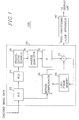
- the image signal decoding system 100 comprises an image signal decoder 20 and a post-processing filter apparatus 40, wherein the image signal decoder 20 includes a variable length decoder(VLD) 22, a run-length decoder(RLD) 24, an inverse zigzag scanner 26, an inverse quantizer 28, an inverse transformer(IT) 30, an adder32, a first frame memory 34 and a motion compensator 36.
- VLD variable length decoder
- RLD run-length decoder
- I inverse transformer
- encoded image data i.e., a set of variable length coded transform coefficients and motion vectors is provided to the VLD 22 on a block-by-block basis.
- the VLD 22 serves to decode the set of variable length coded transform coefficients and the motion vectors to provide run-length coded transform coefficients to the RLD 24 and the motion vectors to the motion compensator 36, respectively.
- the VLD 22 is basically a look-up table: that is, in the VLD 22, a plurality of code sets is provided to define respective relationships between variable length codes and their run-length codes or motion vectors.
- the run-length coded transform coefficients are applied to the RLD 24, which is also a look-up table, for generating zigzag scanned transform coefficients.
- the zigzag scanned transform coefficients are then provided to the inverse zigzag scanner 26.
- the zigzag scanned transform coefficients are reconstructed to provide blocks of quantized transform coefficients.
- Each block of quantized transform coefficients is then converted into a set of transform coefficients at the inverse quantizer 28.
- the set of transform coefficients is fed to the IT 30, e.g., inverse discrete cosine transformer, which transforms the set of transform coefficients into a set of difference data between a block of a current frame and its corresponding block of a previous frame.
- the set of difference data is then sent to the adder 32.
- the motion compensator 36 extracts a set of corresponding pixel data from the previous frame stored in the first frame memory 34 based on a motion vector, which corresponds to each block of the current frame, from the VLD 22 and provides the set of extracted pixel data to the adder 32.
- the set of extracted pixel data from the motion compensator 36 and the set of pixel difference data from the IT 30 are then summed up at the adder 32 to thereby provide reconstructed image data of a given block of the current frame.
- the reconstructed image data or decoded image data of the block is then applied to the first frame memory 34 for the storage thereof and to the post-processing filter apparatus 40.
- post-processing of the decoded image data from the adder 32 is carried out to effectively filter the decoded image data.
- the post-processed image data is transmitted to a display unit(not shown).
- FIG. 2 there is illustrated a detailed block diagram of the post-processing filter apparatus 40 shown in Fig. 1 for explaining the post-processing scheme of the present invention.
- the post-processing filter apparatus 40 which comprises a second frame memory 42, a filter 44, a pixel data evaluation device 46, a switching circuit 47, a pixel data correction device 48 and a controller 49, filters the decoded image data of the current frame by processing each of the pixels within the current frame on a pixel-by-pixel basis.
- the decoded image data of the current frame from the image signal decoder 20 is first stored in the second frame memory 42.
- a pixel value of a target pixel is retrieved and provided to a buffer 48a in the pixel data correction device 48, while pixel data for its neighboring NxN, e.g., 3x3, pixels are fed to the filter 44, wherein the target pixel denotes a pixel to be filtered and is located at the center of the NxN pixels with N being a positive integer.
- the filter 44 which receives the NxN pixel data from the second frame memory 42, then performs the filtering thereof with a predetermined cutoff frequency to thereby generate filtered target pixel data.
- the filter 44 can be implemented by using such a conventional low pass filter as a Median filter or Laplacian filter well known in the art. It should be noted that the predetermined cutoff frequency of the filter 44 can be determined based on the required image quality of the image decoding system.
- the filtered target pixel data from the filter 44 is supplied to the pixel data evaluation device 46 which contains a difference calculator 46a and a first comparator 46b.
- the difference calculator 46a serves to calculate a difference value between the original target pixel data stored in the buffer 48a and the filtered target pixel data from the filter 44 and converts the difference value into its absolute value.
- the absolute difference value derived at the difference calculator 46a is then applied to the first comparator 46b.
- the first comparator 46b compares the absolute difference value from the difference calculator 46a with a predetermined threshold value TH1, e.g., prestored in a memory(not shown) thereof, to thereby provide a selection signal SC1 to the switching circuit 47, wherein the threshold value TH1 is a positive integer. That is, the output from the first comparator 46b is a logic high selection signal if the absolute difference value is equal to or larger than the predetermined threshold value TH1; and a logic low selection signal if the absolute difference value is smaller than the predetermined threshold value TH1. It should be appreciated that the predetermined threshold value TH1 can be determined based on the required image quality of the image signal decoding system. The logic high or logic low selection signal produced at the first comparator 46b is then fed to the switching circuit 47, a second comparator 48b and the controller.
- a predetermined threshold value TH1 e.g., prestored in a memory(not shown) thereof
- the switching circuit 47 which is responsive to the selection signal SC1 from the first comparator 46b, selectively couples the filtered target pixel data from the filter 44 to the pixel data correction device 48 or the second frame memory 42. Specifically, in response to the logic high selection signal, the filtered target pixel data is coupled to the pixel data correction device 48 which is adapted for correcting the filtered target pixel data; and, in response to the logic low selection signal, the filtered target pixel data is coupled to the second frame memory 42 which is adapted for updating the stored target pixel data with the filtered target pixel data.
- the pixel data correction device 48 includes the buffer 48a, a second comparator 48b and a pixel data correction circuit 48c.
- the pixel data correction device 48 derives compensated target pixel data; and provides the same to the display unit and the second frame memory 42 wherein the stored target pixel data is updated with the compensated target pixel data. That is, in response to the logic high selection signal SC1, the second comparator 48b compares the filtered target pixel data from the filter 44 via the switching circuit 47 with the original, or non-filtered target pixel data from the buffer 48a and generates a compensation signal LC1.
- the second comparator 48b generates a logic high compensation signal if the non-filtered or original target pixel data is larger than the filtered target pixel data; and a logic low compensation signal if it is smaller than the filtered target pixel data.
- the generated compensation signal LC1 from the second comparator 48b is provided to the pixel data correction circuit 48c.
- the pixel data correction circuit 48c in response to the compensation signal LC1, provides the compensated target pixel data based on the non-filtered target pixel data from the buffer 48a and the predetermined threshold value TH1, which is identical to the value prestored in the first comparator 46b.
- the compensated target pixel data is obtained by subtracting the predetermined threshold value TH1 from the non-filtered target pixel data; and if the input thereto is a logic low compensation signal, it is derived by adding the non-filtered original target pixel data and the predetermined threshold value TH1.
- the controller 49 responsive to the selection signal SC1 from the first comparator 46b, controls filtering process of the target pixel. That is, in response to the logic high selection signal, the controller 49 generates a second control signal to the second frame memory 42 to thereby update the stored target pixel data in the memory 42 with the compensated target pixel data from the pixel data correction circuit 48c; and provide from the memory 42 a pixel value for a next target pixel to the buffer 48a and NxN pixel data for the next target pixel to the filter 44 in order to initialize the filtering operation for the next target pixel.
- the controller 49 generates a third control signal to the memory 42 in order to update the stored target pixel data with the filtered target pixel data from the switching circuit 47; and the filtering operation for the target pixel is repeated by providing NxN pixel data including the updated target pixel value from the memory 42 to the filter 44.
- the filtering operation for the target pixel is repeated until the first comparator 46b issues the logic high selection signal or the number of the logic low selection signals issued by the first comparator 46b reaches a predetermined number.
- the controller 49 issues a fourth control signal to the memory 42 to thereby update the stored target pixel data with the filtered target pixel data from the switching circuit 47 and provide the updated target pixel data to the display unit. Subsequently, the controller 49 provides a fifth control signal to the memory 42 thereby initializing the filtering operation for a next target pixel by providing the next target pixel data to the buffer 48a and corresponding NxN pixel data to the filter 44.
- the present invention is capable of substantially reducing or eliminating a blocking effect present at the boundary of a block of decoded image data by effectively performing post-processing filtering operation, thereby improving the image quality.
Claims (2)
- Verfahren für die Verwendung in einem Bildsignal-Dekodiersystem für die Nachverarbeitung auf einer Pixel-zu-Pixel-Basis dekodierter Bilddaten eines aktuellen Frames aus einem Bildsignaldekodierer, der in dem Bildsignal-Dekodiersystem enthalten ist, welches die folgenden Schritte umfaßt:(a) Speichern der dekodierten Bilddaten des aktuellen Frames in einem Speicher;(b) Filtern von in dem Speicher gespeicherten Zielpixeldaten, um gefilterte Zielpixeldaten bereitzustellen, wobei die Zielpixeldaten einen Pixelwert eines zu filternden Pixels darstellen;(c) Berechnen eines Absolutwerts der Differenz zwischen den ursprünglichen Zielpixeldaten und den gefilterten Zielpixeldaten, wobei die ursprünglichen Zielpixeldaten nicht gefilterte Zielpixeldaten darstellen, die in den dekodierten Bilddaten enthalten sind;(d) Aktualisieren der gespeicherten Zielpixeldaten mit den gefilterten Zielpixeldaten, falls der Absolutwert der Differenz kleiner als ein vorbestimmter Schwellwert ist;(e) Wiederholen der Schritte (b) bis (d) N-mal, so lange, bis der Absolutwert der Differenz kleiner als der vorbestimmte Schwellwert ist, und Aktualisieren des gespeicherten Zielpixelwertes mit kompensierten Zielpixeldaten, falls der Absolutwert der Differenz gleich oder größer als der vorbestimmte Schwellwert ist, wobei die kompensierten Zielpixeldaten durch Addieren der ursprünglichen Zielpixeldaten und des vorbestimmten Schwellwertes, falls die ursprünglichen Zielpixeldaten kleiner als die gefilterten Zielpixeldaten sind, und durch Subtrahieren des vorbestimmten Schwellwertes von den ursprünglichen Zielpixeldaten, falls die ursprünglichen Zielpixeldaten größer als die gefilterten Zielpixeldaten sind, bereitgestellt werden; und(f) Wiederholen der Schritte (b) bis (e) für einen nächsten Zielpixel, bis alle Pixel in dem aktuellen Frame nachbearbeitet sind.
- Verfahren nach Anspruch 1, bei welchem der Filterschritt (b) unter Anwendung eines Median-Filters durchgeführt wird.
Applications Claiming Priority (2)
| Application Number | Priority Date | Filing Date | Title |
|---|---|---|---|
| KR19940009477A KR970010087B1 (en) | 1994-04-30 | 1994-04-30 | Postprocessing method for digital image |
| KR9409477 | 1994-04-30 |
Publications (3)
| Publication Number | Publication Date |
|---|---|
| EP0680219A2 EP0680219A2 (de) | 1995-11-02 |
| EP0680219A3 EP0680219A3 (de) | 1996-10-23 |
| EP0680219B1 true EP0680219B1 (de) | 2000-01-12 |
Family
ID=19382232
Family Applications (1)
| Application Number | Title | Priority Date | Filing Date |
|---|---|---|---|
| EP19950106564 Expired - Lifetime EP0680219B1 (de) | 1994-04-30 | 1995-05-02 | Verbessertes Nachbearbeitungsverfahren zur Verwendung in einem Bildsignaldekoder |
Country Status (6)
| Country | Link |
|---|---|
| US (1) | US5694492A (de) |
| EP (1) | EP0680219B1 (de) |
| JP (1) | JPH07303254A (de) |
| KR (1) | KR970010087B1 (de) |
| CN (1) | CN1115898A (de) |
| DE (1) | DE69514406D1 (de) |
Cited By (1)
| Publication number | Priority date | Publication date | Assignee | Title |
|---|---|---|---|---|
| CN100361534C (zh) * | 2004-06-14 | 2008-01-09 | 厦门华侨电子股份有限公司 | 视频编码解码系统中用于去除块效应的方法及装置 |
Families Citing this family (23)
| Publication number | Priority date | Publication date | Assignee | Title |
|---|---|---|---|---|
| US5881180A (en) * | 1996-02-08 | 1999-03-09 | Sony Corporation | Method and apparatus for the reduction of blocking effects in images |
| US5974196A (en) * | 1996-03-15 | 1999-10-26 | Sony Corporation | Method and apparatus for blocking effect reduction in images |
| US5933542A (en) * | 1996-04-24 | 1999-08-03 | Sony Corporation | Method and apparatus for blocking effect reduction in images by post-processing in the spatial domain |
| JPH1070717A (ja) * | 1996-06-19 | 1998-03-10 | Matsushita Electric Ind Co Ltd | 画像符号化装置及び画像復号化装置 |
| DE19626985C1 (de) * | 1996-07-04 | 1998-01-02 | Siemens Ag | Verfahren und Anordnung zur Reduktion von Codierungsartefakten von blockbasierten Bildcodierungsverfahren und objektbasierten Bildcodierungsverfahren |
| US6496605B1 (en) * | 1996-08-02 | 2002-12-17 | United Module Corporation | Block deformation removing filter, image processing apparatus using the same, method of filtering image signal, and storage medium for storing software therefor |
| US5796875A (en) * | 1996-08-13 | 1998-08-18 | Sony Electronics, Inc. | Selective de-blocking filter for DCT compressed images |
| US5761267A (en) * | 1996-12-26 | 1998-06-02 | General Electric Company | Methods and apparatus for simplified filtering of scan data in an imaging system |
| KR100251549B1 (ko) * | 1997-02-28 | 2000-04-15 | 구자홍 | 블로킹 효과 제거 기능을 갖는 디지탈 영상 복호화 장치 |
| KR100243225B1 (ko) * | 1997-07-16 | 2000-02-01 | 윤종용 | 블록화효과 및 링잉잡음 감소를 위한 신호적응필터링방법 및신호적응필터 |
| CN100369488C (zh) * | 1998-05-22 | 2008-02-13 | 松下电器产业株式会社 | 数据块噪声消除装置及点时钟信号控制装置 |
| US6108455A (en) | 1998-05-29 | 2000-08-22 | Stmicroelectronics, Inc. | Non-linear image filter for filtering noise |
| KR100308016B1 (ko) * | 1998-08-31 | 2001-10-19 | 구자홍 | 압축 부호화된 영상에 나타나는 블럭현상 및 링현상 제거방법및 영상 복호화기 |
| US6529638B1 (en) * | 1999-02-01 | 2003-03-04 | Sharp Laboratories Of America, Inc. | Block boundary artifact reduction for block-based image compression |
| IL134182A (en) | 2000-01-23 | 2006-08-01 | Vls Com Ltd | Method and apparatus for visual lossless pre-processing |
| US6753929B1 (en) | 2000-06-28 | 2004-06-22 | Vls Com Ltd. | Method and system for real time motion picture segmentation and superposition |
| US6845180B2 (en) * | 2001-03-16 | 2005-01-18 | Sharp Laboratories Of America, Inc. | Predicting ringing artifacts in digital images |
| WO2002102050A2 (en) * | 2001-06-12 | 2002-12-19 | Digital Interactive Streams, Inc. | System and method for enhancing digital video |
| US7570818B2 (en) * | 2003-10-17 | 2009-08-04 | Hewlett-Packard Development Company, L.P. | Method for deblocking and transcoding a media stream |
| US7903902B2 (en) | 2004-07-26 | 2011-03-08 | Sheraizin Semion M | Adaptive image improvement |
| US7639892B2 (en) | 2004-07-26 | 2009-12-29 | Sheraizin Semion M | Adaptive image improvement |
| US7526142B2 (en) | 2005-02-22 | 2009-04-28 | Sheraizin Vitaly S | Enhancement of decompressed video |
| CN113766224B (zh) * | 2020-06-05 | 2022-11-25 | 杭州海康威视数字技术股份有限公司 | 图像增强方法及装置 |
Family Cites Families (4)
| Publication number | Priority date | Publication date | Assignee | Title |
|---|---|---|---|---|
| US5454051A (en) * | 1991-08-05 | 1995-09-26 | Eastman Kodak Company | Method of reducing block artifacts created by block transform compression algorithms |
| KR0148130B1 (ko) * | 1992-05-18 | 1998-09-15 | 강진구 | 블럭킹아티팩트를 억제시키는 부호화/복호화 방법 및 그 장치 |
| US5379122A (en) * | 1992-10-02 | 1995-01-03 | Xerox Corporation | Decompression of standard ADCT-compressed images |
| JP3466705B2 (ja) * | 1993-05-28 | 2003-11-17 | ゼロックス・コーポレーション | 圧縮画像の圧縮解除方法 |
-
1994
- 1994-04-30 KR KR19940009477A patent/KR970010087B1/ko not_active IP Right Cessation
-
1995
- 1995-04-28 CN CN95104752A patent/CN1115898A/zh active Pending
- 1995-05-01 US US08/431,880 patent/US5694492A/en not_active Expired - Fee Related
- 1995-05-01 JP JP13112595A patent/JPH07303254A/ja active Pending
- 1995-05-02 DE DE69514406T patent/DE69514406D1/de not_active Expired - Lifetime
- 1995-05-02 EP EP19950106564 patent/EP0680219B1/de not_active Expired - Lifetime
Cited By (1)
| Publication number | Priority date | Publication date | Assignee | Title |
|---|---|---|---|---|
| CN100361534C (zh) * | 2004-06-14 | 2008-01-09 | 厦门华侨电子股份有限公司 | 视频编码解码系统中用于去除块效应的方法及装置 |
Also Published As
| Publication number | Publication date |
|---|---|
| KR950030671A (ko) | 1995-11-24 |
| KR970010087B1 (en) | 1997-06-21 |
| EP0680219A3 (de) | 1996-10-23 |
| JPH07303254A (ja) | 1995-11-14 |
| CN1115898A (zh) | 1996-01-31 |
| US5694492A (en) | 1997-12-02 |
| DE69514406D1 (de) | 2000-02-17 |
| EP0680219A2 (de) | 1995-11-02 |
Similar Documents
| Publication | Publication Date | Title |
|---|---|---|
| EP0680219B1 (de) | Verbessertes Nachbearbeitungsverfahren zur Verwendung in einem Bildsignaldekoder | |
| US5852682A (en) | Post-processing method and apparatus for use in a video signal decoding apparatus | |
| US5555028A (en) | Post-processing method and apparatus for use in an image signal decoding system | |
| US5757969A (en) | Method for removing a blocking effect for use in a video signal decoding apparatus | |
| US5787210A (en) | Post-processing method for use in an image signal decoding system | |
| JP3266416B2 (ja) | 動き補償フレーム間符号化復号装置 | |
| KR100203710B1 (ko) | 비트 발생량 조절기능을 갖는 영상 부호화 시스템 | |
| US5555029A (en) | Method and apparatus for post-processing decoded image data | |
| EP0680217B1 (de) | Gerät zur Dekodierung eines Videosignals, das in der Lage ist, Blockeffekte zu reduzieren | |
| KR19980017213A (ko) | 열화영상에 대한 보상기능을 갖는 영상 복호화 시스템 | |
| EP0886972B1 (de) | Verbesserte nachbearbeitung zum entfernen von blockeffekten in einem dekodierten bildsignal | |
| US6061401A (en) | Method and apparatus for selectively encoding/decoding a video signal | |
| JPH0710103B2 (ja) | 画像符号化伝送装置 | |
| JPH09149417A (ja) | 動画像信号復号化装置 | |
| JPH0389792A (ja) | 画像符号化装置 | |
| EP0720373A1 (de) | Verfahren und Vorrichtung zur Kodierung von einem Bildsignal mit regionbasierten Bewegungsvektoren | |
| KR100203676B1 (ko) | 비트 발생량 조절기능을 갖는 영상 부호화 시스템 | |
| KR100229793B1 (ko) | 적응적인 부호화 모드 결정 기능을 갖는 개선된영상부호화시스템 | |
| KR100203677B1 (ko) | 비트 발생량 조절기능을 갖는 영상 부호화 시스템 | |
| KR100203663B1 (ko) | 비트 발생량 조절기능을 갖는 영상 부호화 시스템 | |
| KR100203675B1 (ko) | 비트 발생량 조절기능을 갖는 영상 부호화 시스템 | |
| KR100203678B1 (ko) | 비트 발생량 조절기능을 갖는 영상 부호화 시스템 | |
| KR100203696B1 (ko) | 비트 발생량 조절기능을 갖는 영상 부호화 시스템 | |
| KR100203641B1 (ko) | 영상 처리 장치의 블럭킹 효과 방지 회로 | |
| KR100203697B1 (ko) | 비트 발생량 조절기능을 갖는 영상 부호화 시스템 |
Legal Events
| Date | Code | Title | Description |
|---|---|---|---|
| PUAI | Public reference made under article 153(3) epc to a published international application that has entered the european phase |
Free format text: ORIGINAL CODE: 0009012 |
|
| AK | Designated contracting states |
Kind code of ref document: A2 Designated state(s): DE FR GB NL |
|
| PUAL | Search report despatched |
Free format text: ORIGINAL CODE: 0009013 |
|
| AK | Designated contracting states |
Kind code of ref document: A3 Designated state(s): DE FR GB NL |
|
| 17P | Request for examination filed |
Effective date: 19970414 |
|
| GRAG | Despatch of communication of intention to grant |
Free format text: ORIGINAL CODE: EPIDOS AGRA |
|
| 17Q | First examination report despatched |
Effective date: 19990301 |
|
| GRAG | Despatch of communication of intention to grant |
Free format text: ORIGINAL CODE: EPIDOS AGRA |
|
| GRAH | Despatch of communication of intention to grant a patent |
Free format text: ORIGINAL CODE: EPIDOS IGRA |
|
| GRAH | Despatch of communication of intention to grant a patent |
Free format text: ORIGINAL CODE: EPIDOS IGRA |
|
| GRAA | (expected) grant |
Free format text: ORIGINAL CODE: 0009210 |
|
| AK | Designated contracting states |
Kind code of ref document: B1 Designated state(s): DE FR GB NL |
|
| PG25 | Lapsed in a contracting state [announced via postgrant information from national office to epo] |
Ref country code: NL Free format text: LAPSE BECAUSE OF FAILURE TO SUBMIT A TRANSLATION OF THE DESCRIPTION OR TO PAY THE FEE WITHIN THE PRESCRIBED TIME-LIMIT Effective date: 20000112 Ref country code: FR Free format text: LAPSE BECAUSE OF FAILURE TO SUBMIT A TRANSLATION OF THE DESCRIPTION OR TO PAY THE FEE WITHIN THE PRESCRIBED TIME-LIMIT Effective date: 20000112 |
|
| REF | Corresponds to: |
Ref document number: 69514406 Country of ref document: DE Date of ref document: 20000217 |
|
| PG25 | Lapsed in a contracting state [announced via postgrant information from national office to epo] |
Ref country code: DE Free format text: LAPSE BECAUSE OF FAILURE TO SUBMIT A TRANSLATION OF THE DESCRIPTION OR TO PAY THE FEE WITHIN THE PRESCRIBED TIME-LIMIT Effective date: 20000413 |
|
| PG25 | Lapsed in a contracting state [announced via postgrant information from national office to epo] |
Ref country code: GB Free format text: LAPSE BECAUSE OF NON-PAYMENT OF DUE FEES Effective date: 20000502 |
|
| NLV1 | Nl: lapsed or annulled due to failure to fulfill the requirements of art. 29p and 29m of the patents act | ||
| EN | Fr: translation not filed | ||
| PLBE | No opposition filed within time limit |
Free format text: ORIGINAL CODE: 0009261 |
|
| STAA | Information on the status of an ep patent application or granted ep patent |
Free format text: STATUS: NO OPPOSITION FILED WITHIN TIME LIMIT |
|
| GBPC | Gb: european patent ceased through non-payment of renewal fee |
Effective date: 20000502 |
|
| 26N | No opposition filed |