EP0509532B1 - Flüssigkeitsniveaudetektor - Google Patents
Flüssigkeitsniveaudetektor Download PDFInfo
- Publication number
- EP0509532B1 EP0509532B1 EP92106673A EP92106673A EP0509532B1 EP 0509532 B1 EP0509532 B1 EP 0509532B1 EP 92106673 A EP92106673 A EP 92106673A EP 92106673 A EP92106673 A EP 92106673A EP 0509532 B1 EP0509532 B1 EP 0509532B1
- Authority
- EP
- European Patent Office
- Prior art keywords
- nozzle
- liquid level
- level
- liquid
- electrode
- Prior art date
- Legal status (The legal status is an assumption and is not a legal conclusion. Google has not performed a legal analysis and makes no representation as to the accuracy of the status listed.)
- Expired - Lifetime
Links
- 239000007788 liquid Substances 0.000 title claims description 70
- 229920003002 synthetic resin Polymers 0.000 claims description 6
- 239000000057 synthetic resin Substances 0.000 claims description 6
- 239000000463 material Substances 0.000 description 10
- 238000001514 detection method Methods 0.000 description 8
- 239000011521 glass Substances 0.000 description 3
- 238000000034 method Methods 0.000 description 3
- 239000012811 non-conductive material Substances 0.000 description 3
- 230000010355 oscillation Effects 0.000 description 3
- 210000000601 blood cell Anatomy 0.000 description 2
- 239000004020 conductor Substances 0.000 description 2
- 230000002950 deficient Effects 0.000 description 2
- 230000002411 adverse Effects 0.000 description 1
- 210000004369 blood Anatomy 0.000 description 1
- 239000008280 blood Substances 0.000 description 1
- 239000002131 composite material Substances 0.000 description 1
- 238000007796 conventional method Methods 0.000 description 1
- 230000003247 decreasing effect Effects 0.000 description 1
- 230000000694 effects Effects 0.000 description 1
- 238000007654 immersion Methods 0.000 description 1
- 210000002381 plasma Anatomy 0.000 description 1
- 229920003023 plastic Polymers 0.000 description 1
- 239000004033 plastic Substances 0.000 description 1
- 229920003217 poly(methylsilsesquioxane) Polymers 0.000 description 1
- 230000010356 wave oscillation Effects 0.000 description 1
Images


Classifications
-
- G—PHYSICS
- G01—MEASURING; TESTING
- G01N—INVESTIGATING OR ANALYSING MATERIALS BY DETERMINING THEIR CHEMICAL OR PHYSICAL PROPERTIES
- G01N35/00—Automatic analysis not limited to methods or materials provided for in any single one of groups G01N1/00 - G01N33/00; Handling materials therefor
- G01N35/10—Devices for transferring samples or any liquids to, in, or from, the analysis apparatus, e.g. suction devices, injection devices
- G01N35/1009—Characterised by arrangements for controlling the aspiration or dispense of liquids
-
- G—PHYSICS
- G01—MEASURING; TESTING
- G01F—MEASURING VOLUME, VOLUME FLOW, MASS FLOW OR LIQUID LEVEL; METERING BY VOLUME
- G01F23/00—Indicating or measuring liquid level or level of fluent solid material, e.g. indicating in terms of volume or indicating by means of an alarm
- G01F23/22—Indicating or measuring liquid level or level of fluent solid material, e.g. indicating in terms of volume or indicating by means of an alarm by measuring physical variables, other than linear dimensions, pressure or weight, dependent on the level to be measured, e.g. by difference of heat transfer of steam or water
- G01F23/24—Indicating or measuring liquid level or level of fluent solid material, e.g. indicating in terms of volume or indicating by means of an alarm by measuring physical variables, other than linear dimensions, pressure or weight, dependent on the level to be measured, e.g. by difference of heat transfer of steam or water by measuring variations of resistance of resistors due to contact with conductor fluid
- G01F23/245—Indicating or measuring liquid level or level of fluent solid material, e.g. indicating in terms of volume or indicating by means of an alarm by measuring physical variables, other than linear dimensions, pressure or weight, dependent on the level to be measured, e.g. by difference of heat transfer of steam or water by measuring variations of resistance of resistors due to contact with conductor fluid with a probe moved by an auxiliary power, e.g. meter, to follow automatically the level
-
- G—PHYSICS
- G01—MEASURING; TESTING
- G01N—INVESTIGATING OR ANALYSING MATERIALS BY DETERMINING THEIR CHEMICAL OR PHYSICAL PROPERTIES
- G01N35/00—Automatic analysis not limited to methods or materials provided for in any single one of groups G01N1/00 - G01N33/00; Handling materials therefor
- G01N35/10—Devices for transferring samples or any liquids to, in, or from, the analysis apparatus, e.g. suction devices, injection devices
- G01N35/1009—Characterised by arrangements for controlling the aspiration or dispense of liquids
- G01N2035/1025—Fluid level sensing
Definitions
- the present invention relates to an apparatus for detecting the level of a liquid specimen, for example, in a test tube or tubes in an automatic analyzer.
- a vertically movable mechanism is used for a nozzle for taking up a liquid specimen, such as a blood plasma and corpuscle.
- the conventional technique has been developed for detecting the level of the liquid specimen. It is known to detect the level of a liquid through its electrical conductivity.
- a pair of electrodes are inserted into a test tube in interlock with an associated nozzle and hence moved vertically down relative to the surface level of the liquid specimen.
- an electric current is carried from one electrode to the other electrode through the conduction of the liquid specimen. It is, therefore, possible to detect the surface level of the liquid specimen by detecting the electrical conduction.
- the electrodes can be mounted integral with a nozzle for liquid level detection, as disclosed in USP 4,939,925 and Published Unexamined Japanese Patent Application 61-117460.
- the nozzle Since the test tube is normally narrow in diameter, the nozzle, unless being small-sized, cannot be inserted into the test tube. In particular, a nozzle of synthetic resin is relatively large and improper to insert normally into the test tube.
- Forming the electrodes integral with the nozzle can somewhat decrease their occupation area, but the nozzle by itself becomes expensive and is not suitable as a dispensable one.
- a test tube or both a support stand and nozzle are made of a conductive material and serves as a pair of electrodes.
- the nozzle When the nozzle is immersed in a liquid level, it serves as one electrode against the test tube acting as the other electrode, thus leading to a variation in electrostatic capacitance between the two.
- the immersion of the nozzle in the liquid specimen can be detected based on a variation in their electrostatic capacitance.
- the test tube or support stand is restricted principally to a material of high conductivity because the purpose of the material is to enable the test tube or support stand to act as an electrode. Further, the potential on the support stand is held constant so as to provide a reference against the electrode. For this reason, it is not possible to use any inexpensive synthetic resin and glass, resulting in high cost. In the case where the test tube is shifted relative to the support stand, attention should be paid to any defective electrical contact. Thus the positive detection of the liquid level is, therefore, affected.
- this invention provides an apparatus for detecting a level of a liquid held in a container, which comprises: first and second electrodes arranged with the container set therebetween; generating means, electrically connected to the first electrode, for generating an electrical signal; receiving means, electrically connected to the second electrode, for receiving the electrical signal from the generating means through a route of the first electrode, container and second electrode; a conductive member, electrically connected to a zero potential level common to the generating means and receiving means, vertically movable relative to the level of the liquid; and detecting means for detecting a change of the received electrical signal with respect to a reference electrical signal which is received by the receiving means when the conductive member is not in contact with the liquid level and for determining that the conductive member is in contact with the liquid level, when there is the change of the received electrical signal, so that the liquid level is detected and that the conductive member is not in contact with the liquid level when there is no change of the received electrical signal.
- the conductive member is made of, preferably, a conductive synthetic resin.
- the conductive member may be formed as a nozzle for taking up the liquid.
- the liquid level detector further comprises controlling means for controlling a vertical movement of the nozzle relative to the liquid level based on the determination made by detecting means.
- an electrostatic capacity is involved in a system in which the container for the liquid specimen is set between the opposed electrodes.
- a first electrostatic capacity is created between the first electrode and the container and a second electrostatic capacity between the second electrode and the container and a third electrostatic capacity is created in the container.
- the composite of these electrostatic capacities constitutes an electrostatic capacity in the aforementioned system in that initial state.
- the third electrostatic capacity is lost through the conductive member.
- the amplitude of an electric signal received by the receiving means becomes smaller in that contact state than in the initial state.
- the electric signal received by the receiving means differs depending upon whether there is the initial state or the contact state, it is possible to determine based on the received signal whether or not the conductive member is in contact with the liquid level.
- An advantage of the invention lies in that the liquid level detector is not necessary to insert a pair of electrodes in the container. This ensures the detection of the liquid level even if a relatively narrowed container is used.
- a container of inexpensive material can be employed because it does not need to be made using a conductive material.
- a separate conducive member is provided for the nozzle, then it is possible to employ an inexpensive nozzle, such as a dispensable nozzle.
- any possible defective electrical connection need not be considered when the test tube or both the test tube and support stand are moved, thus ensuring the positive detection of the liquid level.
- the material of the container prevents the external detection of an electrostatic capacity in the container
- various proper materials can be used, such as glass or plastics.
- the shapes of the container and electrodes can be changed or modified for the purpose of analysis intended.
- Fig. 1 shows a first embodiment of the present invention.
- a test tube 6 holding a liquid specimen 4, such as blood corpuscle and blood, therein is placed on a base plate 2 of nonconductive material such that it is set between first and second electrodes 8 and 10.
- a nozzle 12 of nonconductive material is inserted into the test tube 6 to take up the liquid specimen 4.
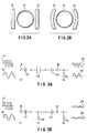
- the electrodes 8 and 10 may be flat plate-like in cross-section as shown in Fig. 2A and curvilinear plate-like as shown in Fig. 2B.
- the first and second electrodes 8 and 10 are electrically connected to an oscillator 14 and receiver 16, respectively.
- a nozzle 12 is electrically connected to a common zero potential level between the oscillator 14 and the receiver 16.
- the oscillator 14 generates a rectangular ware or a sine wave oscillation signal.
- the oscillation signal is supplied from the first electrode 8 via the test tube 6 and second electrode 10 to the receiver 16.
- the receiver 16 supplies a signal output corresponding to its received signal to a determining device 18 where, in accordance with the signal output of the receiver 16, determination is made as to whether or not a tip end 12a of the nozzle 12 is set in contact with a liquid level 4a of the specimen 4.
- the liquid specimen 4 in the test tube 6 is taken up by the nozzle under the suction of a distributor 22 which is connected to the nozzle 12 through a tube 20.
- the nozzle 12 is supported by a vertically movable arm 24 which is moved, by a motor 26, in a vertical direction along a column 28 as indicated by an arrow Z.
- the motor 26 is controlled by a controller 30 on the basis of a control signal of the determining device 18.
- the tip end 12a of the nozzle 12a is placed in an initial state, that is, not in contact with the liquid level 4a.
- the initial state it follows that the tip end 12a of the nozzle is placed at a higher position than the liquid level 4a or there is no specimen 4 present in the test 6.
- a circuit is created among the first electrode 8, test tube 6 and second electrode 10 in a way to be shown in Fig. 3A.
- an electrostatic capacity C1 is created between the first electrode 8 and the test tube 6 and an electrostatic capacity C2 between the second electrode 10 and the test tube 6 and an electrostatic capacity C3 is created in the test tube 6.
- RL in Fig. 3A denotes a zero potential level whereby the electric signal from the first electrode 8 to the second electrode 10 is grounded.
- an electric oscillation signal of the oscillator 14, for example, a sine wave signal P1 is subject to some loss only at these areas of C1, C3 and C2 and supplied, as a sine wave signal, to the receiver 16.
- the nozzle 12 is lowered from the initial state by driving the arm of a Z axis drive mechanism 24. If, in this case, the tip end 12a of the nozzle is brought into contact with the liquid level 4a of the liquid specimen, a common impedance Zs is created, by the nozzle 12, between the electrostatic capacities C1 and C2, as shown in Fig. 3B, instead of the electrostatic capacity C3.
- the energy of the rectangular signal P3 is decreased through the presence of the impedance Zs so that the rectangular wave signal P3 is received, by the receiver 16, at an amplitude level appreciably lower than that of the rectangular wave signal P2.
- the determining device 18 determines its received signal level as a reference signal level indicating that the nozzle is not brought into contact with the liquid level 4a and continues lowering the nozzle 12 under the control of the controller 30.
- the determining device determines based on the received signal level that the tip end of the nozzle 12 has been brought into contact with the liquid level 4a. As a result, the lowering of the nozzle 12 is stopped through the control of the controller 30.
- the specimen 4 is set at a zero potential level, it is possible to decrease the electrode-to-electrode electrostatic capacity to an extremely small extent and hence to make such a determination, by the determining device, with high accuracy.
- the change in level of the electrostatic capacity resulting from the change in level of the received signal as in the case of Figs. 3A and 3B can occur even if the nozzle 12 is made of a material of a low conductivity of the order of a few M ⁇ .
- the nozzle 12 use can be made of an inexpensive disposable nozzle made of a conductive synthetic resin, etc.
- the pair of electrodes 8, 10 are arranged independently of the test tube 6, there is no limit on the material of which the test tube 6 is made. It is thus possible to use an inexpensive nonconductive test tube 6, such as glass or synthetic resin.
- the nozzle 12 continues its downward movement. In order to prevent such an inconvenience, it is possible to impart, to the determining device, a function to determine the presence or absence of the specimen 4 in the test tube 6. If this is the case, then information indicating an amount of descent of the nozzle 12 from the initial position is fed to the device 18 by the controller 30.
- the determining device 18 compares the actual amount of descent of the nozzle 12 which is conveyed as data from the controller 30 with a limit descent level of the nozzle initially set and determines whether or not there is any specimen 4 present.
- the determining device determines that there is no specimen present. In this case, the descent of the nozzle i2 is stopped under the control of the controller 30 and information indicating "the absence of the specimen" is displayed on a proper display means, such as a display unit 34, thus alerting the operator to this state.
- the descent of the nozzle 12 is stopped under the control of the controller 30, displaying information indicating "the presence of the specimen" on the display unit 34.
- the result of determination by the determining device 18 can be utilized not only for the descent control of the nozzle 12 and presence or absence of the specimen 4 but also the suction of the liquid by the distributor 22.
- the controller 30 imparts a suction operation start instruction to the distributor 22 so that the suction of the liquid specimen by the distributor 22 can be started based on the instruction.
- Fig. 4 shows a second embodiment of the present invention. Since the basic structure and operation of the second embodiment are substantially the same as these of the first embodiment, an explanation will be restricted only to their difference.
- the nozzle 12 serves also as a conductive member for detecting the liquid level 4a of the nozzle 12, use in made, in the second embodiment, of a conductive member provided separate from the nozzle 12.
- a conductive rod-like member 32 is electrically connected, in place of the aforementioned conductive member 12, to a zero potential level common to an oscillator 14 and receiver 16.
- the rod-like member 32, together with a nozzle 12, is supported by the arm 24 so that it is vertically movable in interlock with the nozzle 12 with a forward end 32a of the member set flush with a tip end 12a of the nozzle 12.
- nozzle 12 and conductive rod-like member 32 are provided separate from each other, those signals as shown in Figs. 3A and 3B can be detected even if the nozzle 12 is made of a non-conductive material and it is, therefore, possible to achieve the same object as set out in connection with that done in the first embodiment. Since the rod-like member 32 is only one, the diameter of a test tube 6 cannot be so restricted as in a conventional case where a pair of electrodes are employed. It is, therefore, possible to readily insert the rod-like member in the test tube 6.
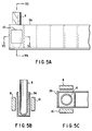
- Figs. 5A to 5C show a third embodiment of the present invention. An explanation of this embodiment is restricted only to a different aspect from those of the first and second embodiments, as will be set out below.
- a liquid level detector of the third embodiment includes a support stand 36 for supporting a plurality of test tubes, one of which is shown in Fig. 5A for brevity's sake.
- a pair of electrodes 8, 10 are located relative to the stand 36 with each test tube 6 between the electrodes 8 and 10. Even in this arrangement, it is possible to detect the level of a liquid as in the same way as set out in connection with the first and second embodiments of the present invention. Since, in this case, any proper material can be used for the stand 36 as in the case of the test tube 6, it is possible to employ an inexpensive material of which the stand is made.
Landscapes
- Physics & Mathematics (AREA)
- General Physics & Mathematics (AREA)
- Chemical & Material Sciences (AREA)
- Fluid Mechanics (AREA)
- Health & Medical Sciences (AREA)
- Life Sciences & Earth Sciences (AREA)
- Thermal Sciences (AREA)
- Analytical Chemistry (AREA)
- Biochemistry (AREA)
- General Health & Medical Sciences (AREA)
- Immunology (AREA)
- Pathology (AREA)
- Automatic Analysis And Handling Materials Therefor (AREA)
- Measurement Of Levels Of Liquids Or Fluent Solid Materials (AREA)
Claims (4)
- Vorrichtung zum Erfassen eines Niveaus (4a) einer Flüssigkeit (4), die in einem Behälter (6) vorliegt, enthaltend:
eine erste und zweite Elektrode (8, 10), die so angeordnet sind, daß die Behälteranordnung dazwischen vorliegt;
eine Generatoreinrichtung (14), die mit der ersten Elektrode (8) elektrisch verbunden ist, um ein elektrisches Signal zu erzeugen;
eine Empfangseinrichtung (16), die mit der zweiten Elektrode (10) elektrisch verbunden ist, um das elektrisches Signal der Generatoreinrichtung (14) über den Weg der ersten Elektrode (8), des Behälters (6) und der zweiten Elektrode (10) zu empfangen;
ein leitfähiges Teil (12, 32), das mit einem gewöhnlichen elektrischen Nullpotential bezüglich der Generatoreinrichtung (14) und der Empfangseinrichtung (16) verbunden und vertikal relativ zum Flüssigkeitsniveau (4a) bewegbar ist; und
eine Detektoreinrichtung (18) zum Erfassen einer Änderung des empfangenen elektrischen Signals im Bezug auf das elektrische Bezugssignal, das durch die Empfangseinrichtung (16) empfangen wird, wenn das leitfähige Teil (12, 32) nicht in Kontakt mit dem Flüssigkeitsstand (4a) ist, und zum Bestimmen, daß das leitfähige Teil (12, 32) in Kontakt mit dem Flüssigkeitsstand (4a) ist, wenn eine Veränderung des empfangenen elektrischen Signals auftritt, so daß der Flüssigkeitsstand (4a) erfaßt ist und daß das leitfähige Teil (12, 32) nicht in Kontakt mit dem Flüssigkeitsstand (4a) ist, wenn keine Veränderung des empfangenen elektrischen Signals auftritt. - Vorrichtung nach Anspruch 1, dadurch gekennzeichnet, daß das leitfähige Teil (12, 32) aus einem leitfähigen Kunstharz hergestellt ist.
- Vorrichtung nach Anspruch 1 oder 2, dadurch gekennzeichnet, daß das leitfähige Teil (12) als Mundstück zur Aufnahme einer Flüssigkeit ausgebildet ist.
- Vorrichtung nach Anspruch 3, gekennzeichnet durch eine weitere enthaltene Einrichtung (30) zur Steuerung einer vertikalen Bewegung des Mundstücks (12) relativ zum Flüssigkeitsstand (4a) auf der Basis der Analyse der Detektoreinrichtung (18).
Applications Claiming Priority (2)
| Application Number | Priority Date | Filing Date | Title |
|---|---|---|---|
| JP86994/91 | 1991-04-18 | ||
| JP3086994A JPH04319624A (ja) | 1991-04-18 | 1991-04-18 | 液面検知装置 |
Publications (3)
| Publication Number | Publication Date |
|---|---|
| EP0509532A2 EP0509532A2 (de) | 1992-10-21 |
| EP0509532A3 EP0509532A3 (en) | 1993-09-01 |
| EP0509532B1 true EP0509532B1 (de) | 1995-11-29 |
Family
ID=13902431
Family Applications (1)
| Application Number | Title | Priority Date | Filing Date |
|---|---|---|---|
| EP92106673A Expired - Lifetime EP0509532B1 (de) | 1991-04-18 | 1992-04-16 | Flüssigkeitsniveaudetektor |
Country Status (4)
| Country | Link |
|---|---|
| US (1) | US5262731A (de) |
| EP (1) | EP0509532B1 (de) |
| JP (1) | JPH04319624A (de) |
| DE (1) | DE69206309T2 (de) |
Families Citing this family (18)
| Publication number | Priority date | Publication date | Assignee | Title |
|---|---|---|---|---|
| US5627522A (en) | 1992-03-27 | 1997-05-06 | Abbott Laboratories | Automated liquid level sensing system |
| DE4331997A1 (de) * | 1993-09-21 | 1995-03-23 | Boehringer Mannheim Gmbh | Verfahren und System zur Mischung von Flüssigkeiten |
| DE69525570T2 (de) | 1994-07-28 | 2002-08-22 | Hitachi, Ltd. | Probensammler für flüssige Proben |
| JP3577917B2 (ja) * | 1997-10-31 | 2004-10-20 | 株式会社日立製作所 | 自動分析装置 |
| US20040248809A1 (en) * | 2003-02-07 | 2004-12-09 | Aventis Pharma Deutschland Gmbh | Use of antagonists of the bradykinin B2 receptor for the treatment of osteoarthrosis |
| CN100546080C (zh) * | 2003-10-23 | 2009-09-30 | 株式会社日立制作所 | 燃料电池装置和电子设备 |
| JP4529451B2 (ja) * | 2003-10-23 | 2010-08-25 | 株式会社日立製作所 | 燃料電池装置及びその制御方法、電子機器 |
| US7219545B2 (en) * | 2004-07-28 | 2007-05-22 | Vertex Pharmaceuticals, Inc. | Sensor for levels of conductive liquids |
| FR2945124B1 (fr) * | 2009-04-29 | 2011-07-08 | Burkert Werke Gmbh & Co Kg | Procede et dispositif de mesure de la concentration d'un analyte dans un liquide echantillon |
| CH702942A1 (de) * | 2010-03-31 | 2011-10-14 | Tecan Trading Ag | Kapazitives Messverfahren und Vorrichtung zur Füllstandsdetektion und entsprechend ausgestattetes Laborgerät. |
| US9599501B2 (en) | 2011-12-29 | 2017-03-21 | Abbott Laboratories | Devices and systems for liquid level detection in hematology instruments, and methods related thereto |
| WO2015098509A1 (ja) * | 2013-12-27 | 2015-07-02 | 株式会社 日立ハイテクノロジーズ | 分析装置 |
| WO2017116963A1 (en) * | 2015-12-30 | 2017-07-06 | Baxter Corporation Englewood | Capacitive single plate bubble detector |
| CN107983237A (zh) * | 2016-01-12 | 2018-05-04 | 梁艳 | 检验用内推式振荡仪 |
| WO2017223214A1 (en) * | 2016-06-22 | 2017-12-28 | Abbott Laboratories | Liquid level sensing apparatus and related methods |
| JP7221929B2 (ja) | 2017-07-10 | 2023-02-14 | ジェン-プローブ・インコーポレーテッド | 容量性流体レベル検出のためのレセプタクルホルダ、システム、および方法 |
| CN109470330B (zh) * | 2018-12-04 | 2020-07-07 | 佛山科学技术学院 | 一种电容式生物试剂液面检测装置及控制方法 |
| CN115867810B (zh) * | 2020-07-03 | 2026-01-27 | 深圳迈瑞生物医疗电子股份有限公司 | 样本分析仪以及样本分析方法 |
Family Cites Families (13)
| Publication number | Priority date | Publication date | Assignee | Title |
|---|---|---|---|---|
| DE2041678A1 (de) * | 1969-09-06 | 1971-03-11 | Greiner Electronic Ag | Verfahren zum Betrieb einer Transferpipette |
| DE3001133A1 (de) * | 1980-01-14 | 1981-07-16 | Vetter, Joachim, 3500 Kassel | Vorrichtung zur kapazitiven pruefung des fuellzustands von gefaessen |
| JPS61117460A (ja) * | 1984-11-14 | 1986-06-04 | Toshiba Corp | 生化学自動分析装置の採取・分注ノズル |
| US4736638A (en) * | 1985-12-20 | 1988-04-12 | Beckman Instruments, Inc. | Liquid level sensor |
| JPH0833320B2 (ja) * | 1986-03-20 | 1996-03-29 | 株式会社東芝 | 自動化学分析装置 |
| US4912976A (en) * | 1987-06-26 | 1990-04-03 | Beckman Instruments, Inc. | Liquid level sensing apparatus |
| JP2582795B2 (ja) * | 1987-08-10 | 1997-02-19 | 株式会社東芝 | 液面検知装置 |
| JP2501460B2 (ja) * | 1988-03-23 | 1996-05-29 | オリンパス光学工業株式会社 | ヘマトクリット値の測定方法 |
| JPH063395B2 (ja) * | 1988-08-26 | 1994-01-12 | 株式会社日立製作所 | 液面検出機能を有する分析装置 |
| US5017909A (en) * | 1989-01-06 | 1991-05-21 | Standex International Corporation | Capacitive liquid level sensor |
| US5083470A (en) * | 1990-01-18 | 1992-01-28 | E. I. Du Pont De Nemours And Company | Capacitive liquid level sensor |
| US5012683A (en) * | 1990-01-18 | 1991-05-07 | E. I. Dupont De Nemours And Company | Capacitive liquid interface sensor |
| US4977786A (en) * | 1990-01-18 | 1990-12-18 | E. I. Du Pont De Nemours And Company | Capacitive liquid level sensor |
-
1991
- 1991-04-18 JP JP3086994A patent/JPH04319624A/ja not_active Withdrawn
-
1992
- 1992-04-16 DE DE69206309T patent/DE69206309T2/de not_active Expired - Fee Related
- 1992-04-16 US US07/869,807 patent/US5262731A/en not_active Expired - Fee Related
- 1992-04-16 EP EP92106673A patent/EP0509532B1/de not_active Expired - Lifetime
Also Published As
| Publication number | Publication date |
|---|---|
| EP0509532A3 (en) | 1993-09-01 |
| JPH04319624A (ja) | 1992-11-10 |
| EP0509532A2 (de) | 1992-10-21 |
| DE69206309D1 (de) | 1996-01-11 |
| DE69206309T2 (de) | 1996-04-25 |
| US5262731A (en) | 1993-11-16 |
Similar Documents
| Publication | Publication Date | Title |
|---|---|---|
| US5262731A (en) | Liquid level detector | |
| EP0633456B1 (de) | Flüssigkeitsstand-Tastsonde und Steuerschaltung | |
| US5027075A (en) | Apparatus for determination of probe contact with a liquid surface | |
| JP2564628Y2 (ja) | 試薬分取装置における泡検知装置 | |
| US4736638A (en) | Liquid level sensor | |
| US6413475B2 (en) | Automatic analysis apparatus with liquid level detection function | |
| JP2799302B2 (ja) | 分析装置 | |
| KR100374592B1 (ko) | 저수레벨 검출기 및 이를 채용한 인쇄기의 저수 레벨측정장치 | |
| EP1261876B1 (de) | Fluidabgabe- und flüssigkeitsoberflächenprüfungssystem | |
| DE69704522D1 (de) | Vorrichtung zum Übertragen von Flüssigkeiten mit Flüssigkeitsstandsmesser | |
| EP0694784B1 (de) | Probensammler für flüssige Proben | |
| JPH0843403A (ja) | 分析装置 | |
| US5582798A (en) | Volume sensing device | |
| GB2068115A (en) | Transferring fluid | |
| JP2001004641A (ja) | 液面検出機能を備えた自動分析装置 | |
| JPH08122126A (ja) | 液面検知装置 | |
| JP3064487B2 (ja) | 液面検知装置 | |
| JPH06241862A (ja) | 液面検知装置 | |
| JP3421556B2 (ja) | 液面検出機能を備えた分析装置 | |
| JPH10246726A (ja) | 搬送ラインにおける容器内の液面検出方法および液面検出装置 | |
| JPH0815277A (ja) | 液定量採取装置 | |
| CN113483855B (zh) | 一种低误差的电容液位检测装置 | |
| JPH07306211A (ja) | 液定量採取装置における液面検知装置 | |
| JPH05232125A (ja) | サンプル吸引検出方法 | |
| JP3665890B2 (ja) | 静電容量形検出装置 |
Legal Events
| Date | Code | Title | Description |
|---|---|---|---|
| PUAI | Public reference made under article 153(3) epc to a published international application that has entered the european phase |
Free format text: ORIGINAL CODE: 0009012 |
|
| 17P | Request for examination filed |
Effective date: 19920512 |
|
| AK | Designated contracting states |
Kind code of ref document: A2 Designated state(s): DE FR GB |
|
| PUAL | Search report despatched |
Free format text: ORIGINAL CODE: 0009013 |
|
| AK | Designated contracting states |
Kind code of ref document: A3 Designated state(s): DE FR GB |
|
| 17Q | First examination report despatched |
Effective date: 19950222 |
|
| GRAA | (expected) grant |
Free format text: ORIGINAL CODE: 0009210 |
|
| AK | Designated contracting states |
Kind code of ref document: B1 Designated state(s): DE FR GB |
|
| REF | Corresponds to: |
Ref document number: 69206309 Country of ref document: DE Date of ref document: 19960111 |
|
| ET | Fr: translation filed | ||
| PGFP | Annual fee paid to national office [announced via postgrant information from national office to epo] |
Ref country code: GB Payment date: 19960409 Year of fee payment: 5 |
|
| PGFP | Annual fee paid to national office [announced via postgrant information from national office to epo] |
Ref country code: DE Payment date: 19960603 Year of fee payment: 5 |
|
| PGFP | Annual fee paid to national office [announced via postgrant information from national office to epo] |
Ref country code: FR Payment date: 19960718 Year of fee payment: 5 |
|
| PLBE | No opposition filed within time limit |
Free format text: ORIGINAL CODE: 0009261 |
|
| STAA | Information on the status of an ep patent application or granted ep patent |
Free format text: STATUS: NO OPPOSITION FILED WITHIN TIME LIMIT |
|
| 26N | No opposition filed | ||
| PG25 | Lapsed in a contracting state [announced via postgrant information from national office to epo] |
Ref country code: GB Effective date: 19970416 |
|
| GBPC | Gb: european patent ceased through non-payment of renewal fee |
Effective date: 19970416 |
|
| PG25 | Lapsed in a contracting state [announced via postgrant information from national office to epo] |
Ref country code: FR Free format text: LAPSE BECAUSE OF NON-PAYMENT OF DUE FEES Effective date: 19971231 |
|
| PG25 | Lapsed in a contracting state [announced via postgrant information from national office to epo] |
Ref country code: DE Free format text: LAPSE BECAUSE OF NON-PAYMENT OF DUE FEES Effective date: 19980101 |
|
| REG | Reference to a national code |
Ref country code: FR Ref legal event code: ST |