EP0509380A2 - Amélioration pour, ou concernant un connecteur électrique de type contact à pression pour un câble plat et flexible - Google Patents
Amélioration pour, ou concernant un connecteur électrique de type contact à pression pour un câble plat et flexible Download PDFInfo
- Publication number
- EP0509380A2 EP0509380A2 EP92106040A EP92106040A EP0509380A2 EP 0509380 A2 EP0509380 A2 EP 0509380A2 EP 92106040 A EP92106040 A EP 92106040A EP 92106040 A EP92106040 A EP 92106040A EP 0509380 A2 EP0509380 A2 EP 0509380A2
- Authority
- EP
- European Patent Office
- Prior art keywords
- flat
- housing
- flexible cable
- cable
- printed circuit
- Prior art date
- Legal status (The legal status is an assumption and is not a legal conclusion. Google has not performed a legal analysis and makes no representation as to the accuracy of the status listed.)
- Withdrawn
Links
Images


Classifications
-
- H—ELECTRICITY
- H01—ELECTRIC ELEMENTS
- H01R—ELECTRICALLY-CONDUCTIVE CONNECTIONS; STRUCTURAL ASSOCIATIONS OF A PLURALITY OF MUTUALLY-INSULATED ELECTRICAL CONNECTING ELEMENTS; COUPLING DEVICES; CURRENT COLLECTORS
- H01R12/00—Structural associations of a plurality of mutually-insulated electrical connecting elements, specially adapted for printed circuits, e.g. printed circuit boards [PCB], flat or ribbon cables, or like generally planar structures, e.g. terminal strips, terminal blocks; Coupling devices specially adapted for printed circuits, flat or ribbon cables, or like generally planar structures; Terminals specially adapted for contact with, or insertion into, printed circuits, flat or ribbon cables, or like generally planar structures
- H01R12/70—Coupling devices
- H01R12/77—Coupling devices for flexible printed circuits, flat or ribbon cables or like structures
- H01R12/78—Coupling devices for flexible printed circuits, flat or ribbon cables or like structures connecting to other flexible printed circuits, flat or ribbon cables or like structures
-
- H—ELECTRICITY
- H01—ELECTRIC ELEMENTS
- H01R—ELECTRICALLY-CONDUCTIVE CONNECTIONS; STRUCTURAL ASSOCIATIONS OF A PLURALITY OF MUTUALLY-INSULATED ELECTRICAL CONNECTING ELEMENTS; COUPLING DEVICES; CURRENT COLLECTORS
- H01R12/00—Structural associations of a plurality of mutually-insulated electrical connecting elements, specially adapted for printed circuits, e.g. printed circuit boards [PCB], flat or ribbon cables, or like generally planar structures, e.g. terminal strips, terminal blocks; Coupling devices specially adapted for printed circuits, flat or ribbon cables, or like generally planar structures; Terminals specially adapted for contact with, or insertion into, printed circuits, flat or ribbon cables, or like generally planar structures
- H01R12/50—Fixed connections
- H01R12/59—Fixed connections for flexible printed circuits, flat or ribbon cables or like structures
- H01R12/62—Fixed connections for flexible printed circuits, flat or ribbon cables or like structures connecting to rigid printed circuits or like structures
-
- H—ELECTRICITY
- H01—ELECTRIC ELEMENTS
- H01R—ELECTRICALLY-CONDUCTIVE CONNECTIONS; STRUCTURAL ASSOCIATIONS OF A PLURALITY OF MUTUALLY-INSULATED ELECTRICAL CONNECTING ELEMENTS; COUPLING DEVICES; CURRENT COLLECTORS
- H01R12/00—Structural associations of a plurality of mutually-insulated electrical connecting elements, specially adapted for printed circuits, e.g. printed circuit boards [PCB], flat or ribbon cables, or like generally planar structures, e.g. terminal strips, terminal blocks; Coupling devices specially adapted for printed circuits, flat or ribbon cables, or like generally planar structures; Terminals specially adapted for contact with, or insertion into, printed circuits, flat or ribbon cables, or like generally planar structures
- H01R12/70—Coupling devices
- H01R12/7082—Coupling device supported only by cooperation with PCB
Definitions
- the present invention relates to an electric connector, and more particularly to an improvement of an electric connector for permitting a solderless connection between the conductors of a flat, flexible cable and a circuit pattern on a printed circuit board by pressing the conductors of the flat, flexible cable against the circuit pattern.
- a conventional electric connector is composed of male and female parts, which are soldered to the exposed conductors of the stripped end of a flat, flexible cable and to selected conductors of a printed circuit pattern respectively.
- a desired electric connection can be made by coupling the male and female parts of the electric connector. Soldering, however, is a tedious and time-consuming work. In an attempt to eliminate such tedious and time-consuming work, a solderless connection in the form of press contact was proposed.
- This type of solderless connector comprises a housing having a resilient contact piece integrally connected therewith, permitting insertion of a flat, flexible cable to place the conductor surface of the flat, flexible cable in registration with selected part of the circuit pattern on a printed circuit board.
- the resilient contact piece is adapted to push the conductor surface of the flat, flexible cable against the selected parts of the circuit pattern.
- solderless connectors in the prior art have some disadvantages.
- the connector housings of the prior art can be fixed to a printed circuit board by fitting the pins or pegs of the connector housings in corresponding holes of the printed circuit board, but these connector housings have no means to positively hold the flat cable therein.
- the flat cable is held only by a resilient contact piece, which pushes the end of the flat cable against the printed board. If undesired external force should be applied to the flat cable, it is liable to cause the flat cable to change in position. Thus, incomplete electric connection may result, leading to malfunction of the associated electric apparatus.
- one object of the present invention is to provide a solderless connector which permits the exact positioning of a flat, flexible cable in the connector housing, particularly in the area in which a required electric connection is to made between the cable and the printed circuit pattern.
- Another object of the present invention is to provide a solderless connector which is capable of positively holding a flat, flexible cable in the connector housing, thus preventing movement of the flat cable, which otherwise, would be caused by external force.
- an electric connector for connecting a flat, flexible cable to a printed circuit board comprising a housing having front and rear portions and a slot in the housing front portion permitting insertion of a flat, flexible cable.
- a resilient contact piece integrally connected to the housing is adapted to push the conductor surface of the flat, flexible cable against and in registration with selected parts of the circuit pattern on a printed circuit board.
- the housing has a groove formed in its rear portion to accommodate the leading edge of said flat, flexible cable when inserted in said housing.
- the housing also has a flexible lock piece integrally connected to the housing in the vicinity of the cable slot to push the rear side of the flat, flexible cable against the housing preventing the removal of the cable from the housing.
- the free end of said resilient contact piece may have notches formed thereon.
- FIGURE 1 is a perspective top view of a solderless connector according to a first embodiment of the present invention.
- FIGURE 2 is a perspective bottom view of the solderless connector of Fig. 1.
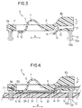
- FIGURE 3 is a section of the solderless connector taken along the line 3-3 in Fig. 2.
- FIGURE 4 is a similar section, but showing how a flat, flexible cable is connected when the solderless connector is applied to a printed circuit board.
- FIGURE 5 is an enlarged perspective view of the free end of the resilient contact piece of the solderless connector.
- FIGURE 6 is an enlarged section, showing the lock piece of the solderless connector.
- FIGURE 7 is an enlarged perspective view of the free end of the resilient contact piece of a solderless connector according to a second embodiment of the present invention.
- FIGURE 8 is an enlarged section, showing the lock piece of a solderless connector according to a third embodiment of the present invention.
- Figs. 1 to 6 show a solderless connector 3 according to a first embodiment of the present invention. It permits a solderless connection between the conductors 2A of a flat, flexible cable 2 and the circuit pattern 1A of a printed circuit board 1 in the form of press contact.
- a plurality of resilient contact pieces 5 are arranged parallel in lateral directions B, and are integrally connected to the lateral side of a housing 4 in the form of cantilevered arms, extending parallel in the longitudinal direction A. These resilient contact pieces 5 are wavy in shape. The free end of each resilient contact piece 5 constitutes a press contact section 6, which extends from a rising section 7.
- the housing 4 has a cable slot 8 passing through its rear portion, permitting insertion of a flat, flexible cable 2 into housing 4.
- split pins 10 are fixed to the four corners of the housing 4 for attaching the housing 4 to a printed circuit board 1, which has holes 9 to catch the pins 10 when inserted therein.
- Each split pin 10 has four enlarged lock quarters 10a separated by slots 10b, thereby providing resiliency.
- the split pin head When the split pin head is inserted in a corresponding hole 9, its diameter reduces yieldingly, thereby allowing the split pin head to pass through the hole 9 and resiliently return to its original, stress-free condition, so that the four enlarged lock quarters 10a may be caught by the rear side 1a of the printed circuit board 1 around the hole 9.
- the connector housing 4 is attached to the printed circuit board 1.
- Housing 4 has a groove 11 made on its front portion 4a, thereby accommodating the leading edge of a flat, flexible cable 2 when inserted in the housing 4. Specifically, after the cable 2 is inserted from the cable slot 8 into the connector housing 4, the cable 2 extends longitudinally on the bottom side of the connector housing 4. The end 2b of the cable 2 is pushed in the groove 11 of the front portion 4a of the conductor housing 4, and then the cable 2 is automatically put in correct position in the conductor housing 4.
- Housing 4 has a lock piece 12 integrally connected in the vicinity of the cable slot 8 of the housing 4 in the form of a short cantilevered arm. Specifically, one end of the lock piece 12 is integrally connected to the housing 4 whereas the free end of the lock piece 12 constitutes a locking arm section 13, which has points 14 formed thereon. A cable insertion gap 15 which is large enough to permit insertion of the cable 2 is defined between the lock piece 12 and the bottom side of the connector housing 4.
- the lock piece 12 When the connector housing 4 having a flat, flexible cable 2 inserted in the cable insertion gap 15, is fixed to a printed circuit board 1, the lock piece 12 is yieldingly bent upwards by the printed circuit board 1 so that the rear side 2C of the cable is pushed towards the ceiling of the connector housing 4.
- the cable 2 cannot be held by the connector housing 4, but when the connector housing 4 is fixed to the printed circuit board 1, the cable 2 is pinched between the ceiling of the connector housing 4 and the upper surface of the lock piece 12.
- the lock piece 15 may have locking points 14 formed thereon.
- One end of the flat, flexible cable 2 is stripped on one side to expose its conductors 2A whereas the other end of the cable 2 is connector to an associated electric apparatus.
- solderless connector 3 The manner in which the solderless connector 3 is used by first inserting one end 2b of a flat, flexible cable 2 into the cable slot 8 of the connector housing 4 to pass through the insertion gap 15 and pass by the free contact end 6 of the resilient contact piece 5.
- the end 2b of the cable 2 is inserted in the groove 11 of the front portion 4a of the connector housing 4.
- the connector housing 4 having the cable 2 inserted therein is fixed to a printed circuit board 1 by inserting its split pins 10 into corresponding holes 9 of the printed circuit board 1.
- the connector housing 4 is positively fixed to the printed circuit board 1, and at the same time, the exposed conductors 2A of the cable 2 are pushed against the printed circuit pattern 1A of the printed circuit board 1 by the resilient contact piece 5 to make electrical contact therebetween.
- the lock piece 12 positively catches the cable 2 in position, preventing it from moving from the correct position.
- solderless connector according to the second embodiment of the present invention is shown. Specifically, the feature of this particular embodiment resides in the press contact portion 6 of the resilient contact piece 5. It has a plurality of parallel slits.
- a solderless connector according to the third embodiment of the present invention is shown.
- the feature of this particular embodiment resides in the press contact portion 6 of the resilient contact piece 5. It has a plurality of feet 17 to push a plurality of flat, flexible cables 2 laid on each other against a printed circuit board 1.
- a flat, flexible cable can be put in correct position in the connector housing with the aid of the groove in the front portion of the connector housing, thereby assuring good electrical contact between the cable and the printed circuit pattern in position.
- the cable conductor is press-contacted to the printed circuit pattern by the resilient contact piece, and the cable is positively held in correct position by the lock piece, thus preventing undesired movement of the cable from the correct position which otherwise, would be caused if an external force should be applied to the cable.
Applications Claiming Priority (2)
| Application Number | Priority Date | Filing Date | Title |
|---|---|---|---|
| JP033924U JPH0597063U (ja) | 1991-04-15 | 1991-04-15 | 電気コネクタ |
| JP33924/91 | 1991-04-15 |
Publications (2)
| Publication Number | Publication Date |
|---|---|
| EP0509380A2 true EP0509380A2 (fr) | 1992-10-21 |
| EP0509380A3 EP0509380A3 (en) | 1995-03-15 |
Family
ID=12400070
Family Applications (1)
| Application Number | Title | Priority Date | Filing Date |
|---|---|---|---|
| EP92106040A Withdrawn EP0509380A3 (en) | 1991-04-15 | 1992-04-08 | Improvement in or relating to a press-contact type electric connector for a flat, flexible cable |
Country Status (4)
| Country | Link |
|---|---|
| US (1) | US5181854A (fr) |
| EP (1) | EP0509380A3 (fr) |
| JP (1) | JPH0597063U (fr) |
| KR (1) | KR950012466B1 (fr) |
Cited By (14)
| Publication number | Priority date | Publication date | Assignee | Title |
|---|---|---|---|---|
| DE19750224A1 (de) * | 1997-11-13 | 1999-06-10 | Daimler Chrysler Ag | Stecker zur Herstellung einer lösbaren elektrischen Verbindung zwischen einem Flachbandkabel und einer Leiterplatte |
| DE19832011A1 (de) * | 1998-07-16 | 2000-02-03 | Kostal Leopold Gmbh & Co Kg | Flachbandleitung mit einem zum lösbaren Verbinden vorgesehenen Anschlußbereich |
| DE19910572A1 (de) * | 1999-03-10 | 2000-09-14 | Delphi Tech Inc | Verbindungselement |
| FR2805668A1 (fr) * | 2000-02-29 | 2001-08-31 | Siemens Automotive Sa | Connecteur par contact pour connecter un cable plat a un circuit imprime |
| EP1154524A1 (fr) * | 2000-05-10 | 2001-11-14 | Sharp Kabushiki Kaisha | Dispositif de borne de connexion pour substrat fexible |
| DE10157803A1 (de) * | 2001-11-27 | 2003-06-12 | Taller Automotive Gmbh | Verbindungsanordnung |
| WO2004040712A1 (fr) * | 2002-10-31 | 2004-05-13 | Fci | Ensemble connecteur dispose entre un cable plat flexible et un composant |
| DE102005056147A1 (de) * | 2005-11-23 | 2007-05-31 | Panta Gmbh | Elektrischer Verbinder |
| US7238032B2 (en) | 2003-10-29 | 2007-07-03 | Fci | Connector arrangement between a flat flex cable and a component |
| WO2010068322A1 (fr) * | 2008-09-30 | 2010-06-17 | Symbol Technologies, Inc. | Connecteur d’e/s sans soudure et scellé |
| DE102012211800A1 (de) * | 2012-07-06 | 2014-01-09 | BSH Bosch und Siemens Hausgeräte GmbH | Elektrische Kontakteinrichtung sowie Anzeige- und/oder Bedienvorrichtung für ein Haushaltsgerät |
| WO2015112659A1 (fr) * | 2014-01-24 | 2015-07-30 | 3M Innovative Properties Company | Connecteur à contact sans soudure |
| US9728865B1 (en) | 2016-04-12 | 2017-08-08 | Symbol Technologies, Llc | Sealed, solderless, replaceable, electrical connector |
| EP4000138A4 (fr) * | 2019-07-16 | 2023-08-23 | CelLink Corporation | Connecteurs sans borne et circuits comprenant des connecteurs sans borne |
Families Citing this family (19)
| Publication number | Priority date | Publication date | Assignee | Title |
|---|---|---|---|---|
| US5399101A (en) * | 1993-12-16 | 1995-03-21 | International Business Machines Corporation | Electrical connector with preloaded contact |
| GB2285893A (en) * | 1994-01-05 | 1995-07-26 | Whitaker Corp | Connector for interconnecting a flexible circuit to a circuit board |
| US5520551A (en) * | 1994-12-01 | 1996-05-28 | The Whitaker Corporation | Molded latching apparatus for printed circuit mounted components |
| US5777855A (en) * | 1996-06-18 | 1998-07-07 | Eastman Kodak Company | Method and apparatus for connecting flexible circuits to printed circuit boards |
| US6000951A (en) * | 1997-03-18 | 1999-12-14 | Prince Corporation | Electrical ribbon wire connectors |
| US5980307A (en) * | 1997-07-23 | 1999-11-09 | Molex Incorporated | Strain relief system for holding cables to circuit boards |
| US6537082B2 (en) | 1997-10-23 | 2003-03-25 | Cinch Connectors, Inc. | Electrical connector |
| JP4947834B2 (ja) * | 1997-11-26 | 2012-06-06 | アプライド マテリアルズ インコーポレイテッド | ダメージフリー被覆刻設堆積法 |
| US5980314A (en) * | 1998-03-13 | 1999-11-09 | Molex Incorporated | Electrical connector with improved board mounting peg |
| JP3684304B2 (ja) * | 1998-09-02 | 2005-08-17 | パイオニア株式会社 | 係止用フック |
| US6676416B1 (en) * | 2000-05-11 | 2004-01-13 | Zyvex Corporation | Ribbon cable and electrical connector for use with microcomponents |
| TW200509329A (en) * | 2003-08-26 | 2005-03-01 | Yung-Shu Yang | LED package material and process |
| KR100671207B1 (ko) * | 2005-08-27 | 2007-01-19 | 삼성전자주식회사 | 기판커넥팅장치 및 이를 갖는 전자장치 |
| US7494344B2 (en) * | 2005-12-29 | 2009-02-24 | Molex Incorporated | Heating element connector assembly with press-fit terminals |
| JP5213629B2 (ja) * | 2008-03-07 | 2013-06-19 | スリーエム イノベイティブ プロパティズ カンパニー | 基板用電線接続構造体及び中継接続体の製造方法並びに中継接続体の固定方法 |
| US8519274B2 (en) | 2011-03-08 | 2013-08-27 | International Business Machines Corporation | Pin that inserts into a circuit board hole |
| US9608367B2 (en) * | 2012-12-11 | 2017-03-28 | Nokia Technologies Oy | Apparatus providing one or more socket contacts for contacting an inserted flexible, planar connector; a method |
| US9413105B2 (en) * | 2014-09-09 | 2016-08-09 | Hon Hai Precision Industry Co., Ltd. | Carrier for flexible printed circuit |
| US10892574B2 (en) * | 2016-10-21 | 2021-01-12 | Paricon Technologies Corporation | Cable-to-board connector |
Citations (3)
| Publication number | Priority date | Publication date | Assignee | Title |
|---|---|---|---|---|
| US4169641A (en) * | 1978-06-22 | 1979-10-02 | Amp Incorporated | Connector clip for flat cable |
| US4634195A (en) * | 1985-06-20 | 1987-01-06 | Amp Incorporated | Electrical interconnection device |
| US4639063A (en) * | 1985-12-20 | 1987-01-27 | Amp Incorporated | Electrical connector for flexible film circuits |
Family Cites Families (4)
| Publication number | Priority date | Publication date | Assignee | Title |
|---|---|---|---|---|
| US4252389A (en) * | 1979-03-27 | 1981-02-24 | Amp Incorporated | Zero insertion force connector having integral unloading means |
| US4252392A (en) * | 1979-09-07 | 1981-02-24 | Amp Incorporated | Zero insertion force connector clip |
| US4358172A (en) * | 1980-04-23 | 1982-11-09 | Thomas & Betts Corporation | Connector for electrical interconnection of circuit board and flat multiconductor cable |
| US4871315A (en) * | 1988-03-30 | 1989-10-03 | Burndy Corporation | Ribbon cable connector |
-
1991
- 1991-04-15 JP JP033924U patent/JPH0597063U/ja active Pending
-
1992
- 1992-03-30 US US07/860,846 patent/US5181854A/en not_active Expired - Fee Related
- 1992-04-08 EP EP92106040A patent/EP0509380A3/en not_active Withdrawn
- 1992-04-14 KR KR1019920006185A patent/KR950012466B1/ko not_active IP Right Cessation
Patent Citations (3)
| Publication number | Priority date | Publication date | Assignee | Title |
|---|---|---|---|---|
| US4169641A (en) * | 1978-06-22 | 1979-10-02 | Amp Incorporated | Connector clip for flat cable |
| US4634195A (en) * | 1985-06-20 | 1987-01-06 | Amp Incorporated | Electrical interconnection device |
| US4639063A (en) * | 1985-12-20 | 1987-01-27 | Amp Incorporated | Electrical connector for flexible film circuits |
Cited By (22)
| Publication number | Priority date | Publication date | Assignee | Title |
|---|---|---|---|---|
| DE19750224A1 (de) * | 1997-11-13 | 1999-06-10 | Daimler Chrysler Ag | Stecker zur Herstellung einer lösbaren elektrischen Verbindung zwischen einem Flachbandkabel und einer Leiterplatte |
| DE19750224B4 (de) * | 1997-11-13 | 2005-10-06 | Daimlerchrysler Ag | Stecker zur Herstellung einer lösbaren elektrischen Verbindung zwischen einem Flachbandkabel und einer Leiterplatte |
| DE19832011A1 (de) * | 1998-07-16 | 2000-02-03 | Kostal Leopold Gmbh & Co Kg | Flachbandleitung mit einem zum lösbaren Verbinden vorgesehenen Anschlußbereich |
| DE19832011B4 (de) * | 1998-07-16 | 2005-12-22 | Leopold Kostal Gmbh & Co. Kg | Flachbandleitung mit einem zum lösbaren Verbinden vorgesehenen Anschlußbereich |
| US6383004B1 (en) | 1999-03-10 | 2002-05-07 | Delphi Technologies, Inc. | Connection element for connecting electrical leads |
| DE19910572A1 (de) * | 1999-03-10 | 2000-09-14 | Delphi Tech Inc | Verbindungselement |
| FR2805668A1 (fr) * | 2000-02-29 | 2001-08-31 | Siemens Automotive Sa | Connecteur par contact pour connecter un cable plat a un circuit imprime |
| EP1154524A1 (fr) * | 2000-05-10 | 2001-11-14 | Sharp Kabushiki Kaisha | Dispositif de borne de connexion pour substrat fexible |
| US6514089B2 (en) | 2000-05-10 | 2003-02-04 | Sharp Kabushiki Kaisha | Terminal connecting device for flexible substrate |
| DE10157803A1 (de) * | 2001-11-27 | 2003-06-12 | Taller Automotive Gmbh | Verbindungsanordnung |
| WO2004040712A1 (fr) * | 2002-10-31 | 2004-05-13 | Fci | Ensemble connecteur dispose entre un cable plat flexible et un composant |
| US7144256B2 (en) | 2002-10-31 | 2006-12-05 | Fci | Connector arrangement between a flexible ribbon cable and a component |
| US7238032B2 (en) | 2003-10-29 | 2007-07-03 | Fci | Connector arrangement between a flat flex cable and a component |
| DE102005056147A1 (de) * | 2005-11-23 | 2007-05-31 | Panta Gmbh | Elektrischer Verbinder |
| EP1791218A3 (fr) * | 2005-11-23 | 2007-10-17 | Panta GmbH | Connecteur électrique |
| WO2010068322A1 (fr) * | 2008-09-30 | 2010-06-17 | Symbol Technologies, Inc. | Connecteur d’e/s sans soudure et scellé |
| US7833025B2 (en) | 2008-09-30 | 2010-11-16 | Symbol Technologies, Inc. | Sealed, solderless I/O connector |
| DE102012211800A1 (de) * | 2012-07-06 | 2014-01-09 | BSH Bosch und Siemens Hausgeräte GmbH | Elektrische Kontakteinrichtung sowie Anzeige- und/oder Bedienvorrichtung für ein Haushaltsgerät |
| WO2015112659A1 (fr) * | 2014-01-24 | 2015-07-30 | 3M Innovative Properties Company | Connecteur à contact sans soudure |
| US9825389B2 (en) | 2014-01-24 | 2017-11-21 | 3M Innovative Properties Company | Connector providing solderless contact |
| US9728865B1 (en) | 2016-04-12 | 2017-08-08 | Symbol Technologies, Llc | Sealed, solderless, replaceable, electrical connector |
| EP4000138A4 (fr) * | 2019-07-16 | 2023-08-23 | CelLink Corporation | Connecteurs sans borne et circuits comprenant des connecteurs sans borne |
Also Published As
| Publication number | Publication date |
|---|---|
| JPH0597063U (ja) | 1993-12-27 |
| EP0509380A3 (en) | 1995-03-15 |
| US5181854A (en) | 1993-01-26 |
| KR920020779A (ko) | 1992-11-21 |
| KR950012466B1 (ko) | 1995-10-18 |
Similar Documents
| Publication | Publication Date | Title |
|---|---|---|
| US5181854A (en) | Press-contact type electric connector for a flat, flexible cable | |
| EP0189234B1 (fr) | Connecteur avec moyen de rétention de conducteur | |
| US5257948A (en) | Printed circuit board mounting device for electrical connectors | |
| JP2582043B2 (ja) | 電気コネクタ組立体 | |
| EP0706240A1 (fr) | Connecteurs électriques entre deux plaquettes à circuits imprimés | |
| EP0682385B1 (fr) | Connecteur électrique | |
| EP0961352B1 (fr) | Connecteur multibroche pour cable plat | |
| US5057027A (en) | Female terminal for an electrical connector | |
| US5415573A (en) | Edge mounted circuit board electrical connector | |
| EP0866528A1 (fr) | Connecteur électrique ayant un bras d'engagement | |
| JPH0411346Y2 (fr) | ||
| EP0519317A2 (fr) | Connecteur de bord pour contenir et maintenir un câble plat en parallèle au circuit imprimée | |
| US4708416A (en) | Electrical connecting terminal for a connector | |
| JPH02273473A (ja) | 電気コネクタ及びその電気端子 | |
| EP0780931B1 (fr) | Connecteur pour des câbles plats | |
| EP0632549B1 (fr) | Ensemble connecteur électrique | |
| US4645277A (en) | Connector for connecting boards | |
| US20020127904A1 (en) | Relay connector | |
| US6273748B1 (en) | Electrical connector assembly | |
| EP0724782B1 (fr) | Prise modulaire jumelee | |
| GB2278510A (en) | Connector for flat cables | |
| CN216903566U (zh) | 按压组件及其连接器 | |
| EP0259964A1 (fr) | Connecteur électrique pour câble plat et flexible | |
| JP3100655B2 (ja) | ネジなしf形コネクタ座 | |
| JP2581080Y2 (ja) | エッジコネクター |
Legal Events
| Date | Code | Title | Description |
|---|---|---|---|
| PUAI | Public reference made under article 153(3) epc to a published international application that has entered the european phase |
Free format text: ORIGINAL CODE: 0009012 |
|
| AK | Designated contracting states |
Kind code of ref document: A2 Designated state(s): DE FR GB IT |
|
| PUAL | Search report despatched |
Free format text: ORIGINAL CODE: 0009013 |
|
| AK | Designated contracting states |
Kind code of ref document: A3 Designated state(s): DE FR GB IT |
|
| 17P | Request for examination filed |
Effective date: 19950826 |
|
| STAA | Information on the status of an ep patent application or granted ep patent |
Free format text: STATUS: THE APPLICATION IS DEEMED TO BE WITHDRAWN |
|
| 18D | Application deemed to be withdrawn |
Effective date: 19961101 |