EP0961352B1 - Connecteur multibroche pour cable plat - Google Patents
Connecteur multibroche pour cable plat Download PDFInfo
- Publication number
- EP0961352B1 EP0961352B1 EP99201673A EP99201673A EP0961352B1 EP 0961352 B1 EP0961352 B1 EP 0961352B1 EP 99201673 A EP99201673 A EP 99201673A EP 99201673 A EP99201673 A EP 99201673A EP 0961352 B1 EP0961352 B1 EP 0961352B1
- Authority
- EP
- European Patent Office
- Prior art keywords
- pin
- contact arms
- connector
- insulative housing
- flat cable
- Prior art date
- Legal status (The legal status is an assumption and is not a legal conclusion. Google has not performed a legal analysis and makes no representation as to the accuracy of the status listed.)
- Expired - Lifetime
Links
Images


Classifications
-
- H—ELECTRICITY
- H01—ELECTRIC ELEMENTS
- H01R—ELECTRICALLY-CONDUCTIVE CONNECTIONS; STRUCTURAL ASSOCIATIONS OF A PLURALITY OF MUTUALLY-INSULATED ELECTRICAL CONNECTING ELEMENTS; COUPLING DEVICES; CURRENT COLLECTORS
- H01R12/00—Structural associations of a plurality of mutually-insulated electrical connecting elements, specially adapted for printed circuits, e.g. printed circuit boards [PCB], flat or ribbon cables, or like generally planar structures, e.g. terminal strips, terminal blocks; Coupling devices specially adapted for printed circuits, flat or ribbon cables, or like generally planar structures; Terminals specially adapted for contact with, or insertion into, printed circuits, flat or ribbon cables, or like generally planar structures
- H01R12/70—Coupling devices
- H01R12/82—Coupling devices connected with low or zero insertion force
- H01R12/85—Coupling devices connected with low or zero insertion force contact pressure producing means, contacts activated after insertion of printed circuits or like structures
- H01R12/87—Coupling devices connected with low or zero insertion force contact pressure producing means, contacts activated after insertion of printed circuits or like structures acting automatically by insertion of rigid printed or like structures
-
- H—ELECTRICITY
- H01—ELECTRIC ELEMENTS
- H01R—ELECTRICALLY-CONDUCTIVE CONNECTIONS; STRUCTURAL ASSOCIATIONS OF A PLURALITY OF MUTUALLY-INSULATED ELECTRICAL CONNECTING ELEMENTS; COUPLING DEVICES; CURRENT COLLECTORS
- H01R12/00—Structural associations of a plurality of mutually-insulated electrical connecting elements, specially adapted for printed circuits, e.g. printed circuit boards [PCB], flat or ribbon cables, or like generally planar structures, e.g. terminal strips, terminal blocks; Coupling devices specially adapted for printed circuits, flat or ribbon cables, or like generally planar structures; Terminals specially adapted for contact with, or insertion into, printed circuits, flat or ribbon cables, or like generally planar structures
- H01R12/70—Coupling devices
- H01R12/77—Coupling devices for flexible printed circuits, flat or ribbon cables or like structures
- H01R12/777—Coupling parts carrying pins, blades or analogous contacts
-
- H—ELECTRICITY
- H01—ELECTRIC ELEMENTS
- H01R—ELECTRICALLY-CONDUCTIVE CONNECTIONS; STRUCTURAL ASSOCIATIONS OF A PLURALITY OF MUTUALLY-INSULATED ELECTRICAL CONNECTING ELEMENTS; COUPLING DEVICES; CURRENT COLLECTORS
- H01R12/00—Structural associations of a plurality of mutually-insulated electrical connecting elements, specially adapted for printed circuits, e.g. printed circuit boards [PCB], flat or ribbon cables, or like generally planar structures, e.g. terminal strips, terminal blocks; Coupling devices specially adapted for printed circuits, flat or ribbon cables, or like generally planar structures; Terminals specially adapted for contact with, or insertion into, printed circuits, flat or ribbon cables, or like generally planar structures
- H01R12/70—Coupling devices
- H01R12/82—Coupling devices connected with low or zero insertion force
-
- H—ELECTRICITY
- H01—ELECTRIC ELEMENTS
- H01R—ELECTRICALLY-CONDUCTIVE CONNECTIONS; STRUCTURAL ASSOCIATIONS OF A PLURALITY OF MUTUALLY-INSULATED ELECTRICAL CONNECTING ELEMENTS; COUPLING DEVICES; CURRENT COLLECTORS
- H01R13/00—Details of coupling devices of the kinds covered by groups H01R12/70 or H01R24/00 - H01R33/00
- H01R13/02—Contact members
- H01R13/193—Means for increasing contact pressure at the end of engagement of coupling part, e.g. zero insertion force or no friction
Definitions
- the present invention relates to electrical connectors for flat cables, and more particularly relates to a low insertion force (LIF) connector for providing an external electrical interface for an internal flat cable of an electrical device.
- LIF low insertion force
- LIF and ZIF relate to the technology of providing an electrical connector with the means in which conductors are inserted into the connector under relatively friction free and damage free conditions. Such connectors are typically soldered or otherwise affixed to an internal circuit board of an electrical device. An FPC or FFC is inserted into the connector and held in place to ensure positive electrical contact between the conductors of the FPC or FFC and the terminals of the connector.
- Various means of inserting and holding the FPC or FFC using low or zero insertion force are used to prevent damage to the FPC or FFC or damage to the components of the connector.
- U.S. Patent No. 5,562,487 to Ii et al. discloses an electrical connector having an actuator which is slidably inserted in the connector housing.
- the actuator has a flat surface portion upon which a flat flexible cable may lie during friction free insertion of the actuator and cable into the housing.
- the flexible flat cable makes electrical contact with the terminals of the connector.
- the terminals include solder tails which extend out of the connector housing which are soldered to a printed circuit board.
- U.S. Patent No. 4,640,562 to Shoemaker discloses a surface mounting means for an electrical connector to a printed circuit board which includes a wedge plate for forcing contact of the flexible cable to the terminals of the connector.
- the connector is releasably mounted to the surface of the circuit board making electrical contact between the terminals and the conductors of the circuit board.
- US 5 308 262 discloses a connector for a flat cable.
- the connector comprises a number of terminal members.
- Each terminal member comprises a connecting finger, a contact finger and an anchoring finger.
- the contact finger is configured for engaging a flat cable for making an electrical connection to the cable lines thereof.
- the cable is inserted and retained using an elongated body having a length substantially equal to the width of a housing of the connector. The elongated body and cable are inserted between the contact finger and the anchoring finger.
- US 5 507 650 discloses a data connector having an exterior portion adapted for connection to a ribbon cable and an interior portion adapted for mating connection with a mating connector of a carrier.
- FIG. 1 shows a conventional external multi-pin connector 100 for a flat flexible cable 101.
- the conventional connector 100 is provided with box-pin terminals 102 having solder tails 103 which engage through holes of the flat flexible cable.
- a strain relief bar 104 is also provided on the connector to hold the cable in place.
- the other end of the cable is connected to the external connector by through hole tin-lead soldering.
- soldering involves targeting the through holes of the flex cable to the solder tails after passing the cable through the connector's strain relief bar.
- a low insertion force multi-pin connector for a flat flexible cable generally includes an elongate insulative housing, a plurality of conductive terminals mounted in the housing and an insulative slide member.
- the insulative housing includes a tail side, a header side, a longitudinal slot disposed on the tail side, a plurality of slits disposed on the tail side and arranged perpendicularly across the longitudinal slot and a plurality of apertures extending from the header side which are in communication with respective slits.
- the conductive terminals each comprise a pin portion and two contact arms, each contact arm being capable of being outwardly deflected.
- the terminals are mounted within respective slits of the insulative housing such that the pin portions protrude through the apertures of the header side and the contact arms form generally parallel rows of upper and lower contact arms on the tail side.
- the insulative slide member is shaped to be inserted, along with the flat flexible cable, into the longitudinal slot of the tail side of the housing.
- the flat cable is first inserted into the longitudinal slot of the housing between the upper and lower contact arms.
- the slide member is then inserted into the longitudinal slot pressing the flat cable against either the upper or lower rows of contact arms thereby making electrical connection between the flat cable and the terminals.
- the connector is configured to be mounted to an external surface of an electrical device such that the header side of the housing projects outwardly to provide external electrical connection to the pin portions of the terminals.
- the multi-pin connector may be shaped to provide straight electrical connection or right-angle electrical connection.
- the terminals are shaped such that the contact arms extend in an opposite direction as the pin portion and the header side and the tail side of the insulative housing are on opposite generally parallel surfaces.
- the terminals are installed within the insulative housing in a configuration in which every other terminal is rotated 180° forming two rows of pin portions protruding through the header side of the insulative housing.
- the terminals are shaped such that the pin portion extends perpendicularly to the contact arms and the header side and tail side of the insulative housing are disposed on perpendicular surfaces.
- the terminals are formed in one of two shapes, the first shape having the pin portion extending perpendicularly from a contact arm at an upper location and the second shape having the pin portion extending from the contact arm at a lower location.
- the terminals are then installed in the housing in alternating shapes forming two rows of pin portions protruding through the header side of the housing.
- the pin portions of the terminal are preferably laterally offset from the plane of the contact arms.
- the contact arms also include J-shaped end portions facing inwardly between the contact arms to provide better contact between the terminals and the flat cable.
- the slide member preferably includes an upper surface having an inclined portion adapted to bias the flat flexible cable into contact with one of the rows of contact arms when the flat cable and slide member are inserted in the longitudinal slot of the housing.
- the slide member and the insulative housing also preferably include a cooperating latch and socket mechanism for releasably retaining the slide member in the longitudinal slot of the insulative housing.
- Multi-pin connector 10 generally includes an elongate insulative housing 11, a plurality of conductive terminals 12 and an insulative slide member 13.
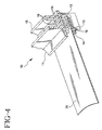
- the multi-pin connector may be in a straight line configuration as shown in Figures 2 and 3 or may be in a right-angle configuration as shown in Figure 4 .
- the insulative housing 11 is made of a non-conducting insulative material and is generally rectangular in shape.
- the housing 11 has a tail side 14, and a header side 15.
- the connector 10 may be configured in the straight-line configuration, where the tail side 14 and the header side 15 are on opposite sides of the housing 11.
- the connector 10 may be configured in the right-angle configuration, where the tail side 14 is perpendicular to the header side 15. Extending almost along the entire length of the tail side 14 is a longitudinal slot 16.
- the width and depth of the slot 16 are sized to receive the slide member 13 and a flexible flat cable as discussed further below. Perpendicularly crossing the longitudinal slot 16 are a series of parallel slits 17.
- the slits 17 are sized to receive the terminals 12. Extending from the header side 15 of the housing 11 are a series of apertures 18 arranged generally in two parallel rows. Each aperture connects to a respective slit 17 and is sized to frictionally hold a pin portion of a terminal 12.
- the terminals 12 are preferably made from a thin electrically conductive metallic material. Each terminal includes a pin portion 19 and two contact arms 20 in a U-shaped configuration. Contact arms 20 are preferably J-shaped, the ends of which face inward. The terminals 12 must be made as to permit resilient outward deflection of the contact arms without damaging the terminals.
- the terminals for a straight-line connector are shaped such that the pin portion 19 extends in an opposite direction as the contact arms 20.
- the pin portion is off center with respect to the contact arms.
- the straight line connector requires only one shape for the terminals.
- the terminals 12 are inserted into the terminal slits 17 of the insulative housing 11 from the tail side 14 so that the pin portions 19 are frictionally held by the apertures 18 and protrude through the header side 15.
- the terminals 12 are installed in the terminal slits 17 of the housing 11 in a configuration in which every other terminal is axially rotated 180° with respect to the previous one, thereby defining two rows of laterally staggered pin portions protruding through the header side of the insulative housing as shown in Figures 2 and 3 .
- the pin portion 19 of the terminal 12 extends perpendicularly to the contact arms 20 as shown in Figure 6 .
- the terminals 20 are preferably provided in two shapes, the first shape having the pin portion extending perpendicularly from an upper location of one of the contact arms and the second shape having the pin portion extending perpendicularly from a lower location of a contact arm.
- the right-angle terminals are inserted in the housing in alternating shapes to form two rows of pin portions protruding through the header side of the housing as shown in Figure 4 .
- the pin portions 19 are preferably offset from the plane of the contact arms 20 such that when installed in the housing the pin portions of two adjacent terminals form a vertical pair. In this manner, the pin portions protruding through the header side of the insulative housing will define a series of parallel vertical pairs.
- the slide member 13 is preferably made from the same insulative material as the housing 11.
- the slide member 13 is roughly the same length as the longitudinal slot 16 and is shaped to be laterally inserted within the slot along with a flat flexible cable.
- the slide member 13 preferably includes an upper surface 21 having an inclined portion 22 which is adapted to bias the flat cable into contact with the upper row of contact arms as discussed further below.
- Attached to the sides of the slide member 13 are flexible spring fingers 23 which are capable of slight inward deflection. Each spring finger 23 has a latch projection 24 which cooperatively engages a socket 25 of the insulative housing when the slide member is inserted within the longitudinal slot.
- a flat flexible cable 26 having exposed contact pads 27 is first inserted into the longitudinal slot 16 between the rows of contact arms 20 of the terminals 12.
- the slide member 13 is then inserted between the flat flexible cable 26 and the lower row of contact arms.
- the inclined portion 22 of the upper surface 21 gently presses the flat cable against the upper row of contact arms making electrical connection between the flat flexible cable and the terminals.
- the slide member 13 is inserted into the longitudinal slot 16 further until the latch projections 24 engage the sockets 25 of the housing.
- the spring latch and socket combination releasably retains the slide member within the longitudinal slot of the housing thereby maintaining the flat flexible cable within the connector and against the upper row of contact arms of the terminals.
- the multi-pin connector 10 is mounted to an external surface of an electrical device such that the header side 15 projects outwardly from the electrical device allowing for external electrical connection to the pin portions of the terminals.
- an internal flat flexible cable of an electrical device is connected to an external port of the device without the need for soldering.
- the flat flexible cable is quickly and easily connected to the multi-pin connector and may be easily disconnected by releasing the latch of the slide member from the socket of the housing and removing the slide member.
Claims (10)
- Un connecteur multibroche (10), pour fournir une interface électrique externe pour un câble plat (26) interne d'un dispositif électrique, le câble plat ayant des parties conductrices (27) exposées sur une surface individuelle de celui-ci, ledit connecteur comprenant :- un boîtier isolant (11) allongé, ayant un côté queue (14), un côté tête (15) et une découpure longitudinale (16), disposée sur ledit côté queue ;- une pluralité de bornes conductrices (12), comprenant chacune une partie de broche (19) et deux bras de contact (20) ayant une configuration en forme de U, de manière à définir une paire de pattes globalement parallèles, capables d'être déformées vers l'extérieur, chaque borne étant montée à l'intérieur du boîtier isolant en formant des rangées globalement parallèles, composées de bras de contact supérieurs et inférieurs, sur ledit côté queue, lesdites parties de broche faisant saillie à travers ledit côté tête ; et- un organe coulissant (13) isolant, conformé pour être inséré latéralement à l'intérieur de ladite découpure longitudinale avec le câble plat,- dans lequel le câble plat est inséré dans ladite découpure longitudinale, entre lesdites rangées supérieures et inférieures de bras de contact, et ledit organe coulissant est inséré dans ladite découpure longitudinale, entre le câble plat et l'une desdites rangées, et presse élastiquement les parties conductrices exposées de la surface individuelle du câble plat contre l'autre desdites rangées, en établissant une connexion électrique interne entre les parties conductrices et lesdites bornes, et- dans lequel ledit connecteur est configuré de manière à être monté sur le dispositif électrique, de manière que ledit côté tête fasse saillie à l'extérieur d'une surface externe du dispositif électrique, pour fournir une connexion électrique externe avec lesdites parties de broche ;- dans lequel ledit organe coulissant comprend un verrou élastique (23, 24) déformable, formé d'une seule pièce avec lui, et ledit boîtier comprend une prise femelle de réception de verrou (25), pour venir en prise de façon désolidarisable avec ledit verrou, pour retenir de façon désolidarisable ledit organe coulissant à l'intérieur dudit boîtier, ledit relâchement dudit verrou vis-à-vis de ladite prise femelle entraînant la déconnexion dudit câble plat vis-à-vis desdites bornes.
- Le connecteur multibroche tel que défini selon la revendication 1, dans lequel le boîtier isolant comprend en outre une pluralité de fentes (17) et d'ouvertures (18), lesdites découpures étant disposées sur le côté queue et agencées perpendiculairement sur la découpure et lesdites ouvertures s'étendant depuis le côté tête, chaque ouverture étant en communication avec une fente respective, et dans lequel les bornes conductrices sont montées dans lesdites fentes respectives du boîtier isolant, en formant des rangées globalement parallèles de bras de contact supérieurs et inférieurs sur le côté queue, les parties de broche faisant saillie à travers lesdites ouvertures du côté tête.
- Le connecteur multibroche tel que défini selon la revendication 1, dans lequel chaque borne est de forme telle que les bras de contact s'étendent dans un sens opposé à celui de la partie de broche, et dans lequel le côté tête et le côté queue du boîtier isolant sont globalement parallèles, en formant une connexion électrique rectiligne entre ledit côté tête et ledit côté queue.
- Le connecteur multibroche tel que défini selon la revendication 3, dans lequel les bornes sont installées à l'intérieur du boîtier isolant, en une configuration dans laquelle chaque autre borne est tournée axialement de 180° par rapport à la précédente, qui définit deux rangées de parties de broche faisant saillie par le côté tête du boîtier isolant.
- Le connecteur multibroche tel que défini selon la revendication 4, dans lequel la partie de broche de chaque borne est décalée latéralement du plan des bras de contact.
- Le connecteur multibroche tel que défini selon la revendication 1, dans lequel chaque borne est de forme telle que la partie de broche s'étend perpendiculairement aux bras de contact, et dans lequel le côté tête et le côté queue du boîtier isolant sont globalement perpendiculaires entre eux en formant une connexion électrique à angle droit entre le côté tête et le côté queue.
- Le connecteur multibroche tel que défini selon la revendication 1, dans lequel la forme de chaque borne est de l'une des deux configurations, la première configuration ayant la partie de broche s'étendant perpendiculairement à partir des bras de contact en un emplacement supérieur, et la deuxième configuration ayant la partie de broche s'étendant à partir des bras de contact en un emplacement inférieur, et dans lequel lesdites bornes sont installées à l'intérieur du boîtier isolant, selon des configurations allant en alternant, définissant deux rangées de parties de broche faisant saillie à travers le côté tête du boîtier isolant.
- Le connecteur multibroche tel que défini selon la revendication 7, dans lequel la partie de broche de chaque borne est décalée latéralement vis-à-vis du plan des bras de contact.
- Le connecteur multibroche tel que défini selon la revendication 1, dans lequel les bras de contact de chaque borne comprennent des parties en forme de J à leurs extrémités, les extrémités desdites parties en forme de J étant tournées vers l'intérieur, entre les bras de contact.
- Le connecteur multibroche tel que défini selon la revendication 1, dans lequel l'organe coulissant comprend une surface supérieure (21), ayant une partie de surface (22) inclinée, adaptée pour solliciter le câble plat afin de le mettre en contact avec l'une des rangées de bras de contact lorsque le câble plat et l'organe coulissant sont insérés dans la découpure longitudinale du boîtier isolant.
Applications Claiming Priority (2)
| Application Number | Priority Date | Filing Date | Title |
|---|---|---|---|
| US09/086,830 US5928029A (en) | 1998-05-29 | 1998-05-29 | Multi-pin connector for flat cable |
| US86830 | 1998-05-29 |
Publications (2)
| Publication Number | Publication Date |
|---|---|
| EP0961352A1 EP0961352A1 (fr) | 1999-12-01 |
| EP0961352B1 true EP0961352B1 (fr) | 2008-05-14 |
Family
ID=22201198
Family Applications (1)
| Application Number | Title | Priority Date | Filing Date |
|---|---|---|---|
| EP99201673A Expired - Lifetime EP0961352B1 (fr) | 1998-05-29 | 1999-05-27 | Connecteur multibroche pour cable plat |
Country Status (6)
| Country | Link |
|---|---|
| US (1) | US5928029A (fr) |
| EP (1) | EP0961352B1 (fr) |
| JP (1) | JP2000030779A (fr) |
| CA (1) | CA2273114A1 (fr) |
| DE (1) | DE69938692D1 (fr) |
| SG (1) | SG75962A1 (fr) |
Cited By (1)
| Publication number | Priority date | Publication date | Assignee | Title |
|---|---|---|---|---|
| WO2011081992A2 (fr) * | 2009-12-31 | 2011-07-07 | Fci | Réseau de connecteurs électriques doté de connecteurs électriques décalés |
Families Citing this family (23)
| Publication number | Priority date | Publication date | Assignee | Title |
|---|---|---|---|---|
| US6244890B1 (en) * | 1998-03-27 | 2001-06-12 | Molex Incorporated | Male electrical connector for flat flexible circuit |
| JP2000252598A (ja) * | 1999-03-02 | 2000-09-14 | Fuji Photo Film Co Ltd | フレキシブルプリント配線板 |
| US6089904A (en) * | 1999-04-16 | 2000-07-18 | Hon Hai Precision Ind. Co., Ltd. | FFC connector |
| TW433638U (en) * | 1999-10-01 | 2001-05-01 | Hon Hai Prec Ind Co Ltd | Electrical connector |
| JP2001176586A (ja) | 1999-12-21 | 2001-06-29 | Citizen Electronics Co Ltd | コネクタ付き発音体 |
| GB0104736D0 (en) * | 2001-02-26 | 2001-04-18 | Varintelligent Bvi Ltd | Electrical cable |
| US6854995B2 (en) * | 2001-11-07 | 2005-02-15 | Tyco Electronics Amp Gmbh | Connector for detachably connecting an electrically conductive foil to a contact |
| TW534493U (en) * | 2002-06-20 | 2003-05-21 | Hon Hai Prec Ind Co Ltd | Electrical connector |
| US7044773B2 (en) * | 2002-08-01 | 2006-05-16 | Ddk Ltd. | Connector |
| US6869308B2 (en) * | 2002-12-11 | 2005-03-22 | Hon Hai Precision Ind. Co., Ltd. | Cable connector having cross-talk suppressing feature and method for making the connector |
| JP4145226B2 (ja) * | 2002-12-26 | 2008-09-03 | 第一電子工業株式会社 | コネクタ |
| CN1993867B (zh) * | 2004-08-10 | 2011-04-27 | 第一电子工业株式会社 | 连接器 |
| JP4578931B2 (ja) * | 2004-10-18 | 2010-11-10 | 第一電子工業株式会社 | コネクタ |
| US7625240B2 (en) * | 2007-10-26 | 2009-12-01 | Cisco Technology, Inc. | Receptacle connector |
| JP2011146223A (ja) * | 2010-01-14 | 2011-07-28 | Yazaki Corp | フラット回路体 |
| BRPI1104453A2 (pt) * | 2010-09-07 | 2015-12-22 | Framatome Connectors Int | arranjo de conector elétrico e método para transmissão de dados de um módulo |
| US8535089B2 (en) | 2011-07-25 | 2013-09-17 | Tyco Electronics Corporation | Connector assembly |
| US8430685B2 (en) * | 2011-07-25 | 2013-04-30 | Tyco Electronics Corporation | Connector assembly |
| JP6074711B2 (ja) * | 2013-09-10 | 2017-02-08 | パナソニックIpマネジメント株式会社 | ケーブル保持部材、電気的接続装置、コネクタ装置 |
| US9373903B2 (en) * | 2014-01-28 | 2016-06-21 | Wei Sun Chang | Flexible flat cable connector and flexible flat cable thereof |
| US9184522B1 (en) | 2014-04-25 | 2015-11-10 | Xerox Corporation | Latch apparatus for retaining a flexible circuit cable within a receptacle mounted on a circuit board |
| DE102015211027A1 (de) * | 2015-06-16 | 2016-12-22 | Zf Friedrichshafen Ag | Spanschutz für Leiterplatten |
| US10211552B2 (en) * | 2016-10-21 | 2019-02-19 | Foxconn Interconnect Technology Limited | Cable connector assembly having space-saving connection between cable wire conductors and contact terminating portions |
Family Cites Families (23)
| Publication number | Priority date | Publication date | Assignee | Title |
|---|---|---|---|---|
| US4367006A (en) * | 1980-12-10 | 1983-01-04 | Amp Incorporated | Connector for flat cable |
| US4449773A (en) * | 1982-05-07 | 1984-05-22 | Amp Incorporated | Low insertion force connector |
| US4477137A (en) * | 1982-08-23 | 1984-10-16 | Allied Corporation | Zero insertion force connector for flat cable |
| US4592611A (en) * | 1984-09-27 | 1986-06-03 | Amp Incorporated | Electrical connector intended for use in confined areas |
| US4640562A (en) * | 1984-12-19 | 1987-02-03 | Amp Incorporated | Surface mounting means for printed circuit board |
| US4624515A (en) * | 1985-04-17 | 1986-11-25 | Thomas & Betts Corporation | Electrical connector with grounding clip |
| GB8810581D0 (en) * | 1988-05-05 | 1988-06-08 | Amp Holland | Zero insertion force connector for wire to board applications |
| US4850899A (en) * | 1988-06-20 | 1989-07-25 | Maynard Scott D | Connector for interfacing a disk drive with a computer |
| US4863395A (en) * | 1989-01-17 | 1989-09-05 | Robert Babuka | Zero insertion force connector with component card |
| US5013264A (en) * | 1989-09-25 | 1991-05-07 | Robinson Nugent, Inc. | Edge card connector having preloaded contacts |
| FR2654557B1 (fr) * | 1989-11-10 | 1992-01-17 | Labinal | Organe de contact electrique male et boiter de connexions electriques correspondant. |
| US5100342A (en) * | 1990-03-30 | 1992-03-31 | Amp Incorporated | High density flat cable connector |
| US5240430A (en) * | 1991-10-31 | 1993-08-31 | Amp Incorporated | Electrical connector for cable to circit board application |
| US5308262A (en) * | 1991-12-10 | 1994-05-03 | Sumitomo Wiring Systems, Ltd. | Electric connector for flexible ribbon cable |
| US5213534A (en) * | 1992-07-31 | 1993-05-25 | Molex Incorporated | Electrical connector assembly for flat flexible cable |
| US5474468A (en) * | 1992-09-14 | 1995-12-12 | Sumitomo Wiring Systems, Ltd. | Connector |
| US5370552A (en) * | 1992-09-16 | 1994-12-06 | Sumitomo Wiring Systems, Ltd. | Electrical connector |
| US5507650A (en) * | 1992-11-16 | 1996-04-16 | Hjs & E Engineering | Universal slide mounted adaptor for storage devices |
| JP2575272Y2 (ja) * | 1993-01-27 | 1998-06-25 | 日本エー・エム・ピー株式会社 | 平形ケーブル用コネクタ |
| US5354214A (en) * | 1993-07-23 | 1994-10-11 | Molex Incorporated | Printed circuit board electrical connector with mounting latch clip |
| JP2593430Y2 (ja) * | 1993-09-09 | 1999-04-12 | エスエムケイ株式会社 | Fpc/ffc用コネクタ |
| JPH07230860A (ja) * | 1994-02-09 | 1995-08-29 | Molex Inc | 電気コネクタ |
| JP3368661B2 (ja) * | 1994-03-04 | 2003-01-20 | 住友電装株式会社 | フラットケーブル用コネクタの嵌合治具 |
-
1998
- 1998-05-29 US US09/086,830 patent/US5928029A/en not_active Expired - Fee Related
-
1999
- 1999-05-26 CA CA002273114A patent/CA2273114A1/fr not_active Abandoned
- 1999-05-27 SG SG1999002733A patent/SG75962A1/en unknown
- 1999-05-27 DE DE69938692T patent/DE69938692D1/de not_active Expired - Fee Related
- 1999-05-27 EP EP99201673A patent/EP0961352B1/fr not_active Expired - Lifetime
- 1999-05-28 JP JP11149490A patent/JP2000030779A/ja active Pending
Cited By (2)
| Publication number | Priority date | Publication date | Assignee | Title |
|---|---|---|---|---|
| WO2011081992A2 (fr) * | 2009-12-31 | 2011-07-07 | Fci | Réseau de connecteurs électriques doté de connecteurs électriques décalés |
| WO2011081992A3 (fr) * | 2009-12-31 | 2011-11-03 | Fci | Réseau de connecteurs électriques doté de connecteurs électriques décalés |
Also Published As
| Publication number | Publication date |
|---|---|
| EP0961352A1 (fr) | 1999-12-01 |
| JP2000030779A (ja) | 2000-01-28 |
| SG75962A1 (en) | 2000-10-24 |
| DE69938692D1 (de) | 2008-06-26 |
| CA2273114A1 (fr) | 1999-11-29 |
| US5928029A (en) | 1999-07-27 |
Similar Documents
| Publication | Publication Date | Title |
|---|---|---|
| EP0961352B1 (fr) | Connecteur multibroche pour cable plat | |
| US4867690A (en) | Electrical connector system | |
| US5127839A (en) | Electrical connector having reliable terminals | |
| US6139373A (en) | Multi-pin electrical connectors | |
| US6162083A (en) | Electrical connector system for flat circuitry | |
| US4891019A (en) | Electrical connector for interconnecting a printed circuit board to a ribbon cable | |
| US5415573A (en) | Edge mounted circuit board electrical connector | |
| EP0630080A2 (fr) | Fiche modulaire téléphonique monté sur une plaquette à circuits imprimés | |
| JPH10502483A (ja) | 非同時電気的接続を行うカードエッジコネクタ | |
| US6733305B2 (en) | Board-to-board electrical connector assembly | |
| US5292265A (en) | Edge mounted circuit board electrical connector | |
| EP0397075A2 (fr) | Connecteur de bordure pour plaque à circuits imprimés | |
| US6561843B1 (en) | FPC connector | |
| EP0632549B1 (fr) | Ensemble connecteur électrique | |
| EP0708502B1 (fr) | Ensemble composé d'un connecteur électrique et d'un circuit imprimé flexible présentant une pièce isolante élastique | |
| US6089883A (en) | Board-to-board connector assembly | |
| EP0856922B1 (fr) | Connecteur de circuit imprimé avec fourche de retenue | |
| US6692273B1 (en) | Straddle mount connector | |
| EP0542068B1 (fr) | Contact électrique femelle | |
| JPH05205823A (ja) | コネクタ組立体 | |
| EP0204475A2 (fr) | Connecteur électrique avec interrupteur | |
| US4679890A (en) | Connector contact terminal | |
| US5980296A (en) | Connecting structure for flat circuit body and connector | |
| JP3898643B2 (ja) | 小型基板対基板コネクタ | |
| US6129573A (en) | ZIF FFC connector having a strain relief |
Legal Events
| Date | Code | Title | Description |
|---|---|---|---|
| PUAI | Public reference made under article 153(3) epc to a published international application that has entered the european phase |
Free format text: ORIGINAL CODE: 0009012 |
|
| AK | Designated contracting states |
Kind code of ref document: A1 Designated state(s): BE CH DE ES FR GB IT LI LU NL SE |
|
| AX | Request for extension of the european patent |
Free format text: AL;LT;LV;MK;RO;SI |
|
| 17P | Request for examination filed |
Effective date: 20000127 |
|
| AKX | Designation fees paid |
Free format text: BE CH DE ES FR GB IT LI LU NL SE |
|
| RAP1 | Party data changed (applicant data changed or rights of an application transferred) |
Owner name: THOMAS & BETTS INTERNATIONAL, INC. |
|
| GRAP | Despatch of communication of intention to grant a patent |
Free format text: ORIGINAL CODE: EPIDOSNIGR1 |
|
| RIC1 | Information provided on ipc code assigned before grant |
Ipc: H01R 12/16 20060101ALI20071116BHEP Ipc: H01R 12/24 20060101ALI20071116BHEP Ipc: H01R 12/38 20060101ALI20071116BHEP Ipc: H01R 12/08 20060101AFI20071116BHEP |
|
| GRAS | Grant fee paid |
Free format text: ORIGINAL CODE: EPIDOSNIGR3 |
|
| GRAA | (expected) grant |
Free format text: ORIGINAL CODE: 0009210 |
|
| AK | Designated contracting states |
Kind code of ref document: B1 Designated state(s): BE CH DE ES FR GB IT LI LU NL SE |
|
| REG | Reference to a national code |
Ref country code: GB Ref legal event code: FG4D |
|
| REG | Reference to a national code |
Ref country code: CH Ref legal event code: EP |
|
| REF | Corresponds to: |
Ref document number: 69938692 Country of ref document: DE Date of ref document: 20080626 Kind code of ref document: P |
|
| PG25 | Lapsed in a contracting state [announced via postgrant information from national office to epo] |
Ref country code: ES Free format text: LAPSE BECAUSE OF FAILURE TO SUBMIT A TRANSLATION OF THE DESCRIPTION OR TO PAY THE FEE WITHIN THE PRESCRIBED TIME-LIMIT Effective date: 20080825 |
|
| NLV1 | Nl: lapsed or annulled due to failure to fulfill the requirements of art. 29p and 29m of the patents act | ||
| PG25 | Lapsed in a contracting state [announced via postgrant information from national office to epo] |
Ref country code: NL Free format text: LAPSE BECAUSE OF FAILURE TO SUBMIT A TRANSLATION OF THE DESCRIPTION OR TO PAY THE FEE WITHIN THE PRESCRIBED TIME-LIMIT Effective date: 20080514 |
|
| REG | Reference to a national code |
Ref country code: CH Ref legal event code: PL |
|
| PG25 | Lapsed in a contracting state [announced via postgrant information from national office to epo] |
Ref country code: SE Free format text: LAPSE BECAUSE OF FAILURE TO SUBMIT A TRANSLATION OF THE DESCRIPTION OR TO PAY THE FEE WITHIN THE PRESCRIBED TIME-LIMIT Effective date: 20080814 Ref country code: LI Free format text: LAPSE BECAUSE OF NON-PAYMENT OF DUE FEES Effective date: 20080531 Ref country code: CH Free format text: LAPSE BECAUSE OF NON-PAYMENT OF DUE FEES Effective date: 20080531 |
|
| PG25 | Lapsed in a contracting state [announced via postgrant information from national office to epo] |
Ref country code: BE Free format text: LAPSE BECAUSE OF FAILURE TO SUBMIT A TRANSLATION OF THE DESCRIPTION OR TO PAY THE FEE WITHIN THE PRESCRIBED TIME-LIMIT Effective date: 20080514 |
|
| PLBE | No opposition filed within time limit |
Free format text: ORIGINAL CODE: 0009261 |
|
| STAA | Information on the status of an ep patent application or granted ep patent |
Free format text: STATUS: NO OPPOSITION FILED WITHIN TIME LIMIT |
|
| 26N | No opposition filed |
Effective date: 20090217 |
|
| PG25 | Lapsed in a contracting state [announced via postgrant information from national office to epo] |
Ref country code: IT Free format text: LAPSE BECAUSE OF FAILURE TO SUBMIT A TRANSLATION OF THE DESCRIPTION OR TO PAY THE FEE WITHIN THE PRESCRIBED TIME-LIMIT Effective date: 20080514 |
|
| PGFP | Annual fee paid to national office [announced via postgrant information from national office to epo] |
Ref country code: FR Payment date: 20090518 Year of fee payment: 11 Ref country code: DE Payment date: 20090528 Year of fee payment: 11 |
|
| PGFP | Annual fee paid to national office [announced via postgrant information from national office to epo] |
Ref country code: GB Payment date: 20090528 Year of fee payment: 11 |
|
| PG25 | Lapsed in a contracting state [announced via postgrant information from national office to epo] |
Ref country code: LU Free format text: LAPSE BECAUSE OF NON-PAYMENT OF DUE FEES Effective date: 20080527 |
|
| GBPC | Gb: european patent ceased through non-payment of renewal fee |
Effective date: 20100527 |
|
| REG | Reference to a national code |
Ref country code: FR Ref legal event code: ST Effective date: 20110131 |
|
| PG25 | Lapsed in a contracting state [announced via postgrant information from national office to epo] |
Ref country code: DE Free format text: LAPSE BECAUSE OF NON-PAYMENT OF DUE FEES Effective date: 20101201 |
|
| PG25 | Lapsed in a contracting state [announced via postgrant information from national office to epo] |
Ref country code: FR Free format text: LAPSE BECAUSE OF NON-PAYMENT OF DUE FEES Effective date: 20100531 |
|
| PG25 | Lapsed in a contracting state [announced via postgrant information from national office to epo] |
Ref country code: GB Free format text: LAPSE BECAUSE OF NON-PAYMENT OF DUE FEES Effective date: 20100527 |