EP0508535B1 - Appareil d'examen à rayons X avec moyens de filtrage - Google Patents
Appareil d'examen à rayons X avec moyens de filtrage Download PDFInfo
- Publication number
- EP0508535B1 EP0508535B1 EP92200955A EP92200955A EP0508535B1 EP 0508535 B1 EP0508535 B1 EP 0508535B1 EP 92200955 A EP92200955 A EP 92200955A EP 92200955 A EP92200955 A EP 92200955A EP 0508535 B1 EP0508535 B1 EP 0508535B1
- Authority
- EP
- European Patent Office
- Prior art keywords
- ray
- holding members
- filter body
- holding member
- filter
- Prior art date
- Legal status (The legal status is an assumption and is not a legal conclusion. Google has not performed a legal analysis and makes no representation as to the accuracy of the status listed.)
- Expired - Lifetime
Links
- 230000008878 coupling Effects 0.000 claims description 8
- 238000010168 coupling process Methods 0.000 claims description 8
- 238000005859 coupling reaction Methods 0.000 claims description 8
- 230000005540 biological transmission Effects 0.000 claims description 5
- 239000002783 friction material Substances 0.000 description 5
- 238000010521 absorption reaction Methods 0.000 description 4
- 230000003287 optical effect Effects 0.000 description 2
- 230000000007 visual effect Effects 0.000 description 2
- RYGMFSIKBFXOCR-UHFFFAOYSA-N Copper Chemical compound [Cu] RYGMFSIKBFXOCR-UHFFFAOYSA-N 0.000 description 1
- OAICVXFJPJFONN-UHFFFAOYSA-N Phosphorus Chemical compound [P] OAICVXFJPJFONN-UHFFFAOYSA-N 0.000 description 1
- 239000011358 absorbing material Substances 0.000 description 1
- 239000004411 aluminium Substances 0.000 description 1
- XAGFODPZIPBFFR-UHFFFAOYSA-N aluminium Chemical compound [Al] XAGFODPZIPBFFR-UHFFFAOYSA-N 0.000 description 1
- 229910052782 aluminium Inorganic materials 0.000 description 1
- 230000002238 attenuated effect Effects 0.000 description 1
- 239000010949 copper Substances 0.000 description 1
- 229910052802 copper Inorganic materials 0.000 description 1
- 230000000694 effects Effects 0.000 description 1
- 210000004072 lung Anatomy 0.000 description 1
- 229910052698 phosphorus Inorganic materials 0.000 description 1
- 239000011574 phosphorus Substances 0.000 description 1
Images


Classifications
-
- A—HUMAN NECESSITIES
- A61—MEDICAL OR VETERINARY SCIENCE; HYGIENE
- A61B—DIAGNOSIS; SURGERY; IDENTIFICATION
- A61B6/00—Apparatus or devices for radiation diagnosis; Apparatus or devices for radiation diagnosis combined with radiation therapy equipment
- A61B6/02—Arrangements for diagnosis sequentially in different planes; Stereoscopic radiation diagnosis
- A61B6/03—Computed tomography [CT]
- A61B6/032—Transmission computed tomography [CT]
-
- A—HUMAN NECESSITIES
- A61—MEDICAL OR VETERINARY SCIENCE; HYGIENE
- A61B—DIAGNOSIS; SURGERY; IDENTIFICATION
- A61B6/00—Apparatus or devices for radiation diagnosis; Apparatus or devices for radiation diagnosis combined with radiation therapy equipment
- A61B6/08—Auxiliary means for directing the radiation beam to a particular spot, e.g. using light beams
-
- A—HUMAN NECESSITIES
- A61—MEDICAL OR VETERINARY SCIENCE; HYGIENE
- A61B—DIAGNOSIS; SURGERY; IDENTIFICATION
- A61B6/00—Apparatus or devices for radiation diagnosis; Apparatus or devices for radiation diagnosis combined with radiation therapy equipment
- A61B6/40—Arrangements for generating radiation specially adapted for radiation diagnosis
- A61B6/4035—Arrangements for generating radiation specially adapted for radiation diagnosis the source being combined with a filter or grating
-
- G—PHYSICS
- G21—NUCLEAR PHYSICS; NUCLEAR ENGINEERING
- G21K—TECHNIQUES FOR HANDLING PARTICLES OR IONISING RADIATION NOT OTHERWISE PROVIDED FOR; IRRADIATION DEVICES; GAMMA RAY OR X-RAY MICROSCOPES
- G21K1/00—Arrangements for handling particles or ionising radiation, e.g. focusing or moderating
- G21K1/10—Scattering devices; Absorbing devices; Ionising radiation filters
Definitions
- the invention relates to a x-ray examination apparatus comprising
- An x-ray examination apparatus of the above- mentioned kind is known from the European Patent EP-B1-157 688.
- the x-ray beam is collimated by two pairs of x-ray absorbing shutters the projection of which onto the patient determines the filed of view. These shutters are movably mounted within a housing that is close to the x-ray source.
- a mirror is present to project light onto the patient from a position corresponding to the position of the x-ray source such as to obtain an optical indication of the field of view.
- An extra filter that can be placed into the x-ray beam is preferably mounted in the same housing with the mirror and the collimating lead shutters and should therefor take up little space.
- a pair of shutters of x-ray absorbing material with a driving mechanism is known from DE-B-1 948 037.
- the driving mechanism comprises a driving rod that is driven by a motor and pivotably attached to a first one of the shutters, the second shutter being coupled to the first one by means of a rack-and- pinion mechanism.
- the driving rod is guided in a spiral groove.
- the filter means take up less space than would have been the case if two separate motors were used. Because by simple mechanical means both rotation and translation of the filter body are performed, the number of components of the filter means is kept small thus, reducing the price of the filter means.
- An embodiment of an x-ray examination apparatus in accordance with the invention is characterized in that the holding members and the filter body are plate-shaped, the filter body being connected to a first holding member in a pivot-point such as to be pivotable in a plane parallel to the holding members, the guiding means comprising a pawl which is provided on the filter body or the second holding member and a groove in the second holding member or in the filter body in which groove the pawl is guided.
- the filter body When the holding members are rotated together, the filter body is clamped between the holding members and rotates with the holding members around the central ray.
- the pawl and the groove force the filter body to pivot around the pivot point and move into the central opening toward or away from the central ray depending on the direction of rotation of the holding members.
- the pawl can be provided on the filter body, in which case the groove is provided in the second holding member that faces the side of the filter body having the pawl.
- the groove is curved and extends in a radial direction.
- the pawl can also be provided on the second holding member in which case the groove runs in the filter body.
- Another embodiment of an x-ray examination apparatus in accordance with the invention is characterized in that the holding members have a toothed circular circumference.
- the holding members can be coupled to a gearwheel of the motor either directly or via a transmission gear. Since the connection requires no intermediate transmission means such as pulleys, chains or drive belts, the number of components of the filter means can remain relatively small.
- an x-ray examination apparatus in accordance with the invention is characterized in that the coupling means comprise a friction member for transmission of rotation of one holding member to the other holding member and a brake for locking one of the holding members.
- Both holding members are for instance each connected to a gearwheel, one of which is driven by the motor. Via a friction member the gearwheels of both the holding members are coupled, such that rotation of the gearwheel that is directly driven by the motor is transferred to the second gearwheel and both holding members rotate together.
- the brake that can be an electromagnetic clutch, the gearwheel of the holding member that is not directly driven by the motor can be blocked. Since the force exerted by the friction member is not large enough to cause rotation of said blocked holding member, only the holding member that is directly driven by the motor is able to rotate.
- Another embodiment of an x-ray examination apparatus in accordance with the invention is characterized in that two filter means are provided as one integral unit which is placed near the x-ray source.
- Figure 1 shows a x-ray examination apparatus comprising a C-shaped frame 2 to which are connected an x-ray source 3 and an x-ray image intensifier tube 5.
- the x-ray source 3 emits a beam of x-rays 7 which after passing through a body 8 is detected on the entrance screen of the image intensifier tube 5.
- the entrance screen that comprises for instance CsI
- a light image is formed which impinges on a photocathode ad liberates electrons therefrom.
- the electrons are accelerated through a potential difference of for instance 20 kV and impinge on an output screen containing phosphorus to form a light image with increased intensity.
- the light image on the output screen of the image intensifier tube 5 is detected with a television camera 9 that forms a video signal which is displayed on a television monitor.
- the C-shaped frame 2 can move in a circumferential direction within a supporting member 11, the supporting member 11 being rotatable around a axis 13.
- a central ray 15 connecting the x-ray source 3 and the x-ray image intensifier tube 5 rotates around a isocentre 17.
- the isocentre 17 In an x-ray image the isocentre 17 always occupies the same position irrespective of the position of the frame 2.
- a table height of a patient table 19 is usually chosen such as to place a area of interest within a patient 8 in the isocentre 17. Close to the x-ray source 3 a collimating unit 21 is placed which contains lead shutters 23 delimiting the x-ray beam 7.
- Figure 2 schematically shows the collimating unit 21 which contains lead shutters 23 that can be moved away from and towards the central ray 15. In total there are four lead shutters 23 enclosing a rectangle. In order to get a visual indication of the collimating effect of the shutters 23 on the x-ray beam 7 an x-ray transparent mirror 25 is present in the collimating unit 21.
- a light source 27, that is in fact contained within the housing 22 of the collimating unit 21, is placed in a position corresponding to a focus 29 of the x-ray source 3.
- the projection of the lead shutters 23 onto the patient 8 by the light source 27 corresponds to the field of view of the x-ray image.
- the filter means 31 that comprises a wedge-shaped filter body 33 of for instance copper or aluminium, is fixed in the housing 22 and can by means of a motor 34 be translated toward and away from the central ray 15 and be rotated around the central ray.
- the motor 34 can be activated by a user of the x-ray examination apparatus from a control panel 35 that can be connected to a side of the patient table 19.
- the filter means 31 can also be placed below the lead shutters 23, or can be used in an x-ray examination apparatus in which no collimating unit 21 is present.
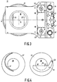
- Figure 3 shows a top view of the filter means 31 in which the filter body 33 is held between two disk-shaped holding members 37 and 37' and is movable within a central opening 39 through which the central ray 15 passes, the central ray being perpendicular to the plane of drawing.
- two filter means are placed on top of one another such that two filter bodies 33 and 33' and four holding member 37 are present.
- the four holding members 37 can be rotated around the central ray 15 by two motors 34 and 34'.
- the signal of the potentiometers 41, 41' is for instance supplied to a control unit for automatic positioning of the filter bodies 33 and 33' in the x-ray beam.
- Figure 4 shows the pair of holding members 37, 37' in a disassembled state.
- the filter body 33 is attached in a pivot-point 43 such as to be rotatable around an axis which runs through the pivot-point and which is perpendicular to the plane of drawing.
- the filter body 33 is provided with a pawl 45 that extends perpendicular to the plane of drawing and that fits in a curved radial groove 47 in the holding member 37'.
- the holding member 37' is to be placed on top of the holding member 37 such that the pawl 45 engages the groove 47.
- the groove 47 forces the filter body 33 to rotate around the pivot-point 43, whereby the filter body 33 covers or uncovers a part of the central opening 39.
- the straight edge 48 of the filter body 33 is rotated around the central ray 15 which extends perpendicular to the plane of drawing.
- Figure 5 shows a schematic representation of the coupling means, comprising a magnetically energizable brake 42 and two spur gears 53 and 55 that are mutually coupled by means of a layer of friction material 54 such as "Ferodo 3701 F” as supplied by the company Ferodo Limited (GB).
- a layer of friction material 54 such as "Ferodo 3701 F” as supplied by the company Ferodo Limited (GB).
- FIG. 6 shows a sectional view of the filter means 31.
- the spur gear 49 is via the spur gear 50 driven by the motor 34.
- the spur gear 51 is coupled to the spur gear 49.
- the spur gears 49 and 51 cause the holding member 37 and 37' to rotate either jointly or relative to one another depending on whether the electromagnetic brake 42 has been energized or not.
- Rotation of the spur gear 51 is transmitted to a spindle 40 that is connected to a potentiometer 41 (not shown in this figure) for recording the angular position of the holding member 37.
- the spur gears 49, 53 and 55 are each connected to respective potentiometers 41 and 41'.
Landscapes
- Health & Medical Sciences (AREA)
- Life Sciences & Earth Sciences (AREA)
- Engineering & Computer Science (AREA)
- Medical Informatics (AREA)
- Physics & Mathematics (AREA)
- High Energy & Nuclear Physics (AREA)
- Radiology & Medical Imaging (AREA)
- Molecular Biology (AREA)
- Veterinary Medicine (AREA)
- Nuclear Medicine, Radiotherapy & Molecular Imaging (AREA)
- Optics & Photonics (AREA)
- Pathology (AREA)
- Public Health (AREA)
- Biomedical Technology (AREA)
- Heart & Thoracic Surgery (AREA)
- Biophysics (AREA)
- Surgery (AREA)
- Animal Behavior & Ethology (AREA)
- General Health & Medical Sciences (AREA)
- Pulmonology (AREA)
- Theoretical Computer Science (AREA)
- Spectroscopy & Molecular Physics (AREA)
- General Engineering & Computer Science (AREA)
- Apparatus For Radiation Diagnosis (AREA)
Claims (5)
- Appareil d'examen à rayons X comprenant- un châssis (2) auquel sont connectés une source de rayons X (3) pour l'émission d'un faisceau de rayons X et un détecteur de rayons X (5) qui est placé a l'opposé de la source de rayons X et- des moyens de filtrage (31) placés entre la source de rayons X (3) et le détecteur de rayons X (5), les moyens de filtrage (31) comprenant un corps de filtrage absorbant des rayons X (33) et des moyens d'entraînement pour le positionnement du corps de filtrage dans le faisceau de rayons X, caractérisé en ce que les moyens d'entraînement comprennent- deux organes de maintien (37, 37') présentant une ouverture centrale (39) positionnée autour d'un rayon central (15) reliant la source de rayons X (3) et le détecteur de rayons X (5), le corps de filtrage (33) étant placé entre les organes de maintien (37, 37') et étant reliés de façon mobile à ces derniers par l'intermédiaire d'un moyen de guidage (45, 47),- un moteur (34) accouplé au moins à un organe de maintien (37, 37') pour la rotation de l'organe de maintien (37, 37') autour du rayon central (15) et- des moyens d'accouplement (42, 54) pour l'accouplement et le désaccouplement des organes de maintien (37, 37'), la rotation combinée des organes de maintien (37, 37') autour du rayon central (15) provoquant la fixation du corps de filtrage (33) par rapport aux organes de maintien, la rotation de l'un des organes de maintien par rapport à l'autre organe de maintien provoquant un déplacement du corps de filtrage par rapport aux organes de maintien par l'intermédiaire des moyens de guidage (45, 47).
- Appareil d'examen à rayons X selon la revendication 1, caractérisé en ce que les organes de maintien (37, 37') et le corps de filtrage (33) présentent une forme plane, le corps de filtrage (33) étant relié à un premier organe de maintien (37) dans un point de pivotement (43) de façon à pouvoir pivoter dans un plan parallèle aux organes de maintien (37, 37'), les moyens de guidage (45, 47) étant munis d'un cliquet (45), qui est prévu sur le corps de filtrage (33) ou le deuxième organe de maintien (37') et d'une rainure (47) dans le deuxième organe de maintien (37') ou dans le corps de filtrage (33), rainure dans laquelle est guidé le cliquet (45).
- Appareil d'examen à rayons X selon la revendication 1 ou 2, caractérisé en ce que les organes de maintien (37, 37') présentent une circonférence circulaire dentée.
- Appareil d'examen à rayons X selon la revendication 1, 2 ou 3, caractérisé en ce que les moyens d'accouplement (42, 54) sont munis d'un organe de friction (42) pour la transmission de la rotation d'un organe de maintien (37') à l'autre organe de maintien (37) et d'un frein (54) pour verrouiller l'un des organes de maintien (37, 37').
- Appareil d'examen à rayons X selon l'une des revendications précédentes, caractérisé en ce que deux moyens de filtrage sont prévus comme une unité intégrale qui est placée près de la source de rayons X.
Applications Claiming Priority (2)
| Application Number | Priority Date | Filing Date | Title |
|---|---|---|---|
| EP91200860 | 1991-04-12 | ||
| EP91200860 | 1991-04-12 |
Publications (2)
| Publication Number | Publication Date |
|---|---|
| EP0508535A1 EP0508535A1 (fr) | 1992-10-14 |
| EP0508535B1 true EP0508535B1 (fr) | 1996-02-07 |
Family
ID=8207606
Family Applications (1)
| Application Number | Title | Priority Date | Filing Date |
|---|---|---|---|
| EP92200955A Expired - Lifetime EP0508535B1 (fr) | 1991-04-12 | 1992-04-03 | Appareil d'examen à rayons X avec moyens de filtrage |
Country Status (4)
| Country | Link |
|---|---|
| US (1) | US5200986A (fr) |
| EP (1) | EP0508535B1 (fr) |
| JP (1) | JP3272392B2 (fr) |
| DE (1) | DE69208130T2 (fr) |
Families Citing this family (6)
| Publication number | Priority date | Publication date | Assignee | Title |
|---|---|---|---|---|
| FI94913C (fi) * | 1994-02-15 | 1995-11-10 | Orion Yhtymae Oy | Röntgenkuvauslaitteen suodinjärjestely |
| FR2770677B1 (fr) * | 1997-11-03 | 1999-12-24 | Ge Medical Syst Sa | Filtre de conformation de faisceau de rayon-x a surface variable et appareil d'imagerie pour rayon-x incorporant un tel filtre |
| US7881555B2 (en) * | 2006-08-29 | 2011-02-01 | Siemens Medical Solutions Usa, Inc. | Methods and systems for reducing bright burn in images |
| CN101789277B (zh) * | 2009-01-24 | 2014-06-11 | Ge医疗系统环球技术有限公司 | 滤波器和x射线成像系统 |
| JP5503919B2 (ja) * | 2009-08-06 | 2014-05-28 | 株式会社東芝 | X線ct装置 |
| US10030961B2 (en) | 2015-11-27 | 2018-07-24 | General Electric Company | Gap measuring device |
Family Cites Families (6)
| Publication number | Priority date | Publication date | Assignee | Title |
|---|---|---|---|---|
| FR1170506A (fr) * | 1956-03-31 | 1959-01-15 | Siemens Reiniger Werke Ag | Dispositif pour le réglage de l'exposition dans les radiographies |
| DE1948037C3 (de) * | 1969-09-23 | 1975-03-06 | Siemens Ag, 1000 Berlin Und 8000 Muenchen | Röntgenzielgerät |
| FR2561516B1 (fr) * | 1984-03-20 | 1988-03-04 | Thomson Cgr | Installation de radiologie a filtre compensateur |
| DE8713933U1 (de) * | 1987-10-16 | 1989-02-09 | Siemens AG, 1000 Berlin und 8000 München | Rotierende, mit einem Schlitz versehene Strahlenblende |
| DE4041296A1 (de) * | 1990-02-16 | 1991-08-22 | Siemens Ag | Primaerstrahlenblende |
| US5107529A (en) * | 1990-10-03 | 1992-04-21 | Thomas Jefferson University | Radiographic equalization apparatus and method |
-
1992
- 1992-04-03 EP EP92200955A patent/EP0508535B1/fr not_active Expired - Lifetime
- 1992-04-03 DE DE69208130T patent/DE69208130T2/de not_active Expired - Fee Related
- 1992-04-06 US US07/864,109 patent/US5200986A/en not_active Expired - Fee Related
- 1992-04-09 JP JP08884992A patent/JP3272392B2/ja not_active Expired - Fee Related
Also Published As
| Publication number | Publication date |
|---|---|
| US5200986A (en) | 1993-04-06 |
| JP3272392B2 (ja) | 2002-04-08 |
| JPH05103776A (ja) | 1993-04-27 |
| DE69208130D1 (de) | 1996-03-21 |
| EP0508535A1 (fr) | 1992-10-14 |
| DE69208130T2 (de) | 1996-08-29 |
Similar Documents
| Publication | Publication Date | Title |
|---|---|---|
| CA1123973A (fr) | Dispositif fluoroscopique de radiographie | |
| US4766603A (en) | Aperture device of radiation diagnostic apparatus | |
| EP0430338A1 (fr) | Appareil d'examen aux rayons X | |
| EP0485998A1 (fr) | Appareil de radiographie | |
| EP0632995A1 (fr) | Appareil radiodiagnostic dentaire | |
| US4670896A (en) | Radiology installation with compensating filter(s) | |
| EP0508535B1 (fr) | Appareil d'examen à rayons X avec moyens de filtrage | |
| JP3579112B2 (ja) | 放射線源のリアルタイム検出装置 | |
| US4731806A (en) | Grid moving apparatus for radiography | |
| US4896344A (en) | X-ray video system | |
| JPH1054876A (ja) | 核カメラ装置 | |
| EP1263217B1 (fr) | Système à rayons X | |
| KR101434753B1 (ko) | 조사범위 조절수단을 구비하는 콜리메이터장치 | |
| US7577233B1 (en) | Rotating X-ray apparatus for inspection of deployed intravascular devices | |
| JP2003051984A5 (fr) | ||
| US4761065A (en) | Inspection device with adjustable viewing screen | |
| JPS60127698A (ja) | X線絞り装置 | |
| US20070297571A1 (en) | X-Ray Emitter and Method for Generating and Representing X-Ray Images | |
| JPH08266523A (ja) | X線撮影装置 | |
| US5224145A (en) | X-ray beam limiting apparatus including pivotable blade | |
| DE19625864A1 (de) | Röntgenaufnahmegerät | |
| JPS6113941A (ja) | スライス位置表示装置 | |
| JPH05292402A (ja) | X線診断装置 | |
| US4210817A (en) | Apparatus for eliminating cross-fogging in biplane radiography | |
| GB2169419A (en) | Inspection device |
Legal Events
| Date | Code | Title | Description |
|---|---|---|---|
| PUAI | Public reference made under article 153(3) epc to a published international application that has entered the european phase |
Free format text: ORIGINAL CODE: 0009012 |
|
| AK | Designated contracting states |
Kind code of ref document: A1 Designated state(s): DE FR GB IT NL |
|
| 17P | Request for examination filed |
Effective date: 19930405 |
|
| 17Q | First examination report despatched |
Effective date: 19941107 |
|
| GRAA | (expected) grant |
Free format text: ORIGINAL CODE: 0009210 |
|
| AK | Designated contracting states |
Kind code of ref document: B1 Designated state(s): DE FR GB IT NL |
|
| PG25 | Lapsed in a contracting state [announced via postgrant information from national office to epo] |
Ref country code: IT Free format text: LAPSE BECAUSE OF FAILURE TO SUBMIT A TRANSLATION OF THE DESCRIPTION OR TO PAY THE FEE WITHIN THE PRE;WARNING: LAPSES OF ITALIAN PATENTS WITH EFFECTIVE DATE BEFORE 2007 MAY HAVE OCCURRED AT ANY TIME BEFORE 2007. THE CORRECT EFFECTIVE DATE MAY BE DIFFERENT FROM THE ONE RECORDED.SCRIBED TIME-LIMIT Effective date: 19960207 Ref country code: NL Free format text: LAPSE BECAUSE OF FAILURE TO SUBMIT A TRANSLATION OF THE DESCRIPTION OR TO PAY THE FEE WITHIN THE PRESCRIBED TIME-LIMIT Effective date: 19960207 |
|
| REF | Corresponds to: |
Ref document number: 69208130 Country of ref document: DE Date of ref document: 19960321 |
|
| ET | Fr: translation filed | ||
| NLV1 | Nl: lapsed or annulled due to failure to fulfill the requirements of art. 29p and 29m of the patents act | ||
| PLBE | No opposition filed within time limit |
Free format text: ORIGINAL CODE: 0009261 |
|
| STAA | Information on the status of an ep patent application or granted ep patent |
Free format text: STATUS: NO OPPOSITION FILED WITHIN TIME LIMIT |
|
| 26N | No opposition filed | ||
| REG | Reference to a national code |
Ref country code: FR Ref legal event code: CD |
|
| REG | Reference to a national code |
Ref country code: GB Ref legal event code: IF02 |
|
| REG | Reference to a national code |
Ref country code: GB Ref legal event code: 746 Effective date: 20021025 |
|
| REG | Reference to a national code |
Ref country code: FR Ref legal event code: D6 |
|
| PGFP | Annual fee paid to national office [announced via postgrant information from national office to epo] |
Ref country code: FR Payment date: 20040427 Year of fee payment: 13 |
|
| PGFP | Annual fee paid to national office [announced via postgrant information from national office to epo] |
Ref country code: GB Payment date: 20040429 Year of fee payment: 13 |
|
| PGFP | Annual fee paid to national office [announced via postgrant information from national office to epo] |
Ref country code: DE Payment date: 20040615 Year of fee payment: 13 |
|
| PG25 | Lapsed in a contracting state [announced via postgrant information from national office to epo] |
Ref country code: GB Free format text: LAPSE BECAUSE OF NON-PAYMENT OF DUE FEES Effective date: 20050403 |
|
| PG25 | Lapsed in a contracting state [announced via postgrant information from national office to epo] |
Ref country code: DE Free format text: LAPSE BECAUSE OF NON-PAYMENT OF DUE FEES Effective date: 20051101 |
|
| GBPC | Gb: european patent ceased through non-payment of renewal fee |
Effective date: 20050403 |
|
| PG25 | Lapsed in a contracting state [announced via postgrant information from national office to epo] |
Ref country code: FR Free format text: LAPSE BECAUSE OF NON-PAYMENT OF DUE FEES Effective date: 20051230 |
|
| REG | Reference to a national code |
Ref country code: FR Ref legal event code: ST Effective date: 20051230 |