EP0508201A2 - Diebstahlsicherungs-Vorrichtung - Google Patents
Diebstahlsicherungs-Vorrichtung Download PDFInfo
- Publication number
- EP0508201A2 EP0508201A2 EP92104966A EP92104966A EP0508201A2 EP 0508201 A2 EP0508201 A2 EP 0508201A2 EP 92104966 A EP92104966 A EP 92104966A EP 92104966 A EP92104966 A EP 92104966A EP 0508201 A2 EP0508201 A2 EP 0508201A2
- Authority
- EP
- European Patent Office
- Prior art keywords
- bow
- casing
- auxiliary element
- bracket
- locking
- Prior art date
- Legal status (The legal status is an assumption and is not a legal conclusion. Google has not performed a legal analysis and makes no representation as to the accuracy of the status listed.)
- Granted
Links
Images
Classifications
-
- G—PHYSICS
- G11—INFORMATION STORAGE
- G11B—INFORMATION STORAGE BASED ON RELATIVE MOVEMENT BETWEEN RECORD CARRIER AND TRANSDUCER
- G11B33/00—Constructional parts, details or accessories not provided for in the other groups of this subclass
- G11B33/02—Cabinets; Cases; Stands; Disposition of apparatus therein or thereon
- G11B33/04—Cabinets; Cases; Stands; Disposition of apparatus therein or thereon modified to store record carriers
- G11B33/0405—Cabinets; Cases; Stands; Disposition of apparatus therein or thereon modified to store record carriers for storing discs
- G11B33/0488—Cabinets; Cases; Stands; Disposition of apparatus therein or thereon modified to store record carriers for storing discs in boxes or containers comprising additional sound reproducing or activating means
-
- E—FIXED CONSTRUCTIONS
- E05—LOCKS; KEYS; WINDOW OR DOOR FITTINGS; SAFES
- E05B—LOCKS; ACCESSORIES THEREFOR; HANDCUFFS
- E05B73/00—Devices for locking portable objects against unauthorised removal; Miscellaneous locking devices
- E05B73/0017—Anti-theft devices, e.g. tags or monitors, fixed to articles, e.g. clothes, and to be removed at the check-out of shops
- E05B73/0023—Containers, boxes, cases or the like, e.g. for compact discs or video-cassettes, specially adapted therefor
-
- G—PHYSICS
- G11—INFORMATION STORAGE
- G11B—INFORMATION STORAGE BASED ON RELATIVE MOVEMENT BETWEEN RECORD CARRIER AND TRANSDUCER
- G11B33/00—Constructional parts, details or accessories not provided for in the other groups of this subclass
- G11B33/02—Cabinets; Cases; Stands; Disposition of apparatus therein or thereon
- G11B33/04—Cabinets; Cases; Stands; Disposition of apparatus therein or thereon modified to store record carriers
- G11B33/0405—Cabinets; Cases; Stands; Disposition of apparatus therein or thereon modified to store record carriers for storing discs
- G11B33/0411—Single disc boxes
- G11B33/0416—Single disc boxes for disc cartridges
-
- Y—GENERAL TAGGING OF NEW TECHNOLOGICAL DEVELOPMENTS; GENERAL TAGGING OF CROSS-SECTIONAL TECHNOLOGIES SPANNING OVER SEVERAL SECTIONS OF THE IPC; TECHNICAL SUBJECTS COVERED BY FORMER USPC CROSS-REFERENCE ART COLLECTIONS [XRACs] AND DIGESTS
- Y10—TECHNICAL SUBJECTS COVERED BY FORMER USPC
- Y10T—TECHNICAL SUBJECTS COVERED BY FORMER US CLASSIFICATION
- Y10T70/00—Locks
- Y10T70/50—Special application
- Y10T70/5004—For antitheft signaling device on protected article
-
- Y—GENERAL TAGGING OF NEW TECHNOLOGICAL DEVELOPMENTS; GENERAL TAGGING OF CROSS-SECTIONAL TECHNOLOGIES SPANNING OVER SEVERAL SECTIONS OF THE IPC; TECHNICAL SUBJECTS COVERED BY FORMER USPC CROSS-REFERENCE ART COLLECTIONS [XRACs] AND DIGESTS
- Y10—TECHNICAL SUBJECTS COVERED BY FORMER USPC
- Y10T—TECHNICAL SUBJECTS COVERED BY FORMER US CLASSIFICATION
- Y10T70/00—Locks
- Y10T70/50—Special application
- Y10T70/5009—For portable articles
- Y10T70/5031—Receptacle
Definitions
- the present invention relates to an anti-theft device for a box-shaped object intended for sale, in particular a cassette with a data carrier, such as e.g. a compact disk, consisting of a sleeve intended for receiving the object and an insertion opening on a narrow side and signal transmitter for triggering an alarm, as well as locking means arranged on or interacting with it and which can be brought into engagement with the object contained in the sleeve, which can be unlocked with the help of a special tool for the purpose of separating the case and the object.
- a cassette with a data carrier such as e.g. a compact disk, consisting of a sleeve intended for receiving the object and an insertion opening on a narrow side and signal transmitter for triggering an alarm, as well as locking means arranged on or interacting with it and which can be brought into engagement with the object contained in the sleeve, which can be unlocked with the help of a special tool for the purpose of separating the case and the object.
- the cover is usually made of hard plastic, which has to hold a box-shaped object to be secured against theft, such as a CD cassette, the cover being provided with a so-called oscillating circuit label, so that when it passes one at the exit of An induction loop arranged in sales shops triggers an alarm if the case including the object is taken away without payment.
- the reusable sleeve is separated from the CD cassette using a special tool at the cash register of a retail store.
- a wide variety of locking systems are known, for which purpose work is carried out with bolts, pins or hooks which connect the casing to the object until it is unlocked using a special tool.
- the object of the present invention was therefore to create a new type of locking system which can be used regardless of the nature of the sleeves and which can reliably protect an object inserted into the sleeve against theft.
- the task was in particular so far that, in addition to plastic sleeves, those made of hard paper (cardboard) can in principle be used.
- the centerpiece is the bow-shaped auxiliary element, which preferably consists of magnetic material, in particular steel, and can be unlocked by means of a magnet acting on the bow end.
- the bow-shaped auxiliary element is preferably in a longitudinal slot in the associated narrow side the wall of the case guided or fastened longitudinally.
- the length of the bow-shaped auxiliary element is preferably greater than the length of the associated narrow side of the casing, so that the object can be pulled out of the casing at any time. In principle, this could also be achieved in that the sleeve is provided on the side of the insertion opening with recesses which allow the object to be gripped.
- the outer temple end between the actual temple web and the inwardly projecting leg has a corner stiffening in the form of a molded plate extending over the corner.
- the inner temple end has a longitudinal slot, which separates the temple end into two separate sponging tongues, the inwardly projecting retaining leg being provided at the end of one tongue, while at the end of the other, somewhat longer tongue, which also follows is formed on the angled locking lug.
- a run-up slope for the tongue having the holding leg can be provided at the inner end of the narrow casing side guiding the bow-shaped auxiliary element, such that in the inserted position of the bow the inner bow end having the two tongues is forcibly pressed slightly inwards and so that Guaranteed taking the locking position of the locking nose, but without preventing the unlocking.
- the locking slot is preferably located on the narrow side of the casing opposite the insertion opening in the area of the corner between the two right-angled narrow sides.
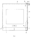
- the locking means here consist of a bow-shaped auxiliary element 3, which is longitudinally displaceable along the narrow side 1a of the casing (the displacement can take place at least over half the length of the narrow side).
- the auxiliary element 3 has two rigid legs 3a, 3c projecting inward at right angles, wherein the box-shaped object 2 is securely caught between these legs 3a, 3c when moved (gripped like a clamp).
- a locking lug 3d which protrudes slightly above the legs 3c, will snap into a locking slot 3e on the narrow side 1c of the casing 1, and can only be unlocked again from this position by means of a strong magnet M.
- the object 2 can be pulled out of the casing together with the auxiliary element, up to an end stop of the auxiliary element 3.
- the lower end of the auxiliary element 3 can also be bent outwards and the object 2 can be completely removed from the casing will. This mechanism is explained in more detail below.
- the auxiliary element 3 could also run freely along the narrow side 1a, i.e. not be held. For practical reasons, however, it is better to hold the auxiliary element 3 in a longitudinally displaceable manner on the narrow side 1a of the casing 1.
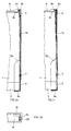
- FIGS. 2 to 6 Further details of the anti-theft device according to the invention can be seen from FIGS. 2 to 6.
- auxiliary element 3 is held displaceably in a longitudinal slot 6 in the narrow side 1a of the casing by means of a rivet 7.
- auxiliary element 3 is stiffened: Between the corner formed by the web 3 and the leg 3a, a stiffening plate 3b is arranged along the edges thereof, the size of which depends on the length of the leg 3a, but can in principle be chosen as desired.
- the plate 3b forms a kind of box bottom between the web 3 and the leg 3a.
- the inner end of the bow-shaped auxiliary element is divided into two tongues 9, 10 by a longitudinal slot 8, the holding leg 3 c at the end of the tongue 9 and the end of the tongue 10, which projects somewhat beyond the tongue 9 , which is also provided inwardly protruding locking lug 3d.
- an inclined slope 5 is provided on the inside of the narrow side 1a, which slightly lifts the tongue 9 when the bow-shaped auxiliary element 3 is inserted in the final phase and presses it inwards against the object.
- the tongue 10 which carries the locking lug 3d, is thus pulled inwards, so that it is securely in the locking slot 3e in the end position and from this position is only with the Allows special tool (magnet M) to be withdrawn from the locking position.
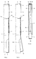
- Fig. 4 of the drawing shows the device with the auxiliary element extended
- Fig. 5 illustrates how, in this position, the lower end of the bow-shaped auxiliary element 3 can be resiliently bent out so that the enclosed object can be pulled out of the casing without any problems.
- This position is also the position which is the insertion of an object to be secured in the bow-shaped auxiliary element (clip) and finally in the protective shell.
- the locking slot 3e is located in the upper narrow side of the casing and can be attached without further problems during the production of the casing.
- the construction shown shows that an extremely safe device can be created with the simplest of means. It is immaterial whether the sleeve is made of hard plastic, soft plastic or even hard paper (cardboard). The use of the bow-shaped auxiliary element also allows secure locking with less hard materials.
Landscapes
- Engineering & Computer Science (AREA)
- Multimedia (AREA)
- Burglar Alarm Systems (AREA)
- Air Bags (AREA)
- Closures For Containers (AREA)
- Transition And Organic Metals Composition Catalysts For Addition Polymerization (AREA)
- Orthopedics, Nursing, And Contraception (AREA)
- Telephone Function (AREA)
Abstract
Description
- Die vorliegende Erfindung betrifft eine Diebstahlsicherungs-Vorrichtung für einen zum Verkauf bestimmten schachtelförmigen Gegenstand, insbesondere eine Kassette mit einem Datenträger, wie z.B. einen Kompakt-Disk, bestehend aus einer zur Aufnahme des Gegenstandes bestimmten und eine Einschuböffnung an einer Schmalseite sowie Signalgeber zum Auslösen eines Alarms aufweisenden Hülle, sowie an dieser angeordneten bzw. mit dieser zusammenwirkenden und mit dem in der Hülle enthaltenen Gegenstand in Eingriff bringbaren Verriegelungsmitteln, die zwecks Trennung von Hülle und Gegenstand mit Hilfe eines Spezialwerkzeuges entriegelbar sind.
- Bei bekannten Vorrichtungen dieser Art besteht die Hülle in der Regel aus hartem Kunststoff, welche einen gegen Diebstahl zu sichernden schachtelförmigen Gegenstand aufzunehmen hat, wie beispielsweise eine CD-Kassette, wobei die Hülle mit einer sogenannten Schwingkreisetikette versehen ist, damit beim Passieren einer am Ausgang von Verkaufsgeschäften angeordneten Induktionsschleife ein Alarm ausgelöst wird, wenn die Hülle einschliesslich des Gegenstandes ohne Bezahlung mitgenommen wird. In der Regel wird an der Kasse eines Verkaufsgeschäftes die wiederverwendbare Hülle mittels eines Spezialwerkzeuges von der CD-Kassette getrennt. Es sind die verschiedensten Verriegelungssysteme bekannt, wobei dazu mit Bolzen, Stiften oder Haken gearbeitet wird, welche die Hülle mit dem Gegenstand solange verbinden, bis eine Entriegelung mit Hilfe eines speziellen Werkzeuges erfolgt.
- Bei den bisher verwendeten Hüllen aus hartem Kunststoff konnten, wie bereits gesagt, die verschiedensten Verriegelungssysteme eingesetzt werden. Ein Nachteil bestand darin, dass eine sichere Verriegelung nicht immer gewährleistet war. Hinzu kommt nun, dass vermehrt aus Umweltschutzgründen die Beschaffenheit der Hüllen geändert werden muss, d.h. dass anstelle von hartem Kunststoff immer mehr weiche, umweltverträglichere Kunststoffe zu verwenden sind. Mit derart sogenannten weichen Hüllen können die meisten der bisherigen Systeme nicht mehr zum Einsatz kommen, da durch Anwendung üblicher Kräfte eine Trennung von Hülle und Gegenstand relativ leicht erfolgen kann. Damit ist selbstverständlich der Sinn der angestrebten Diebstahlsicherungs-Vorrichtung nicht mehr erfüllt.
- Aufgabe der vorliegenden Erfindung war es deshalb, ein neuartiges Verriegelungssystem zu schaffen, welches unabhängig von der Beschaffenheit der Hüllen zur Anwendung gelangen kann und dabei einen in die Hülle eingeführten Gegenstand sicher gegen Diebstahl zu schützen vermag. Die Aufgabe war insbesondere soweit gefasst, dass neben Hüllen aus Kunststoff auch solche aus Hartpapier (Karton) grundsätzlich verwendet werden können.
- Die gestellte Aufgabe wird bei einer Diebstahlsicherungs-Vorrichtung der eingangs definierten Art mittels der Merkmale gemäss Anspruch 1 gelöst.
- Kernstück ist somit das bügelförmige Hilfselement, welches vorzugsweise aus magnetischem Material besteht, insbesondere aus Stahl, und die Entriegelung mittels eines auf das Bügelende einwirkenden Magneten erfolgen kann.
- Das bügelförmige Hilfselement ist vorzugsweise in einem Längsschlitz in der zugehörigen Schmalseite der Hüllenwand längsverschieblich geführt, bzw. befestigt. Die Länge des bügelförmigen Hilfselementes ist vorzugsweise grösser als die Länge der zugehörigen Schmalseite der Hülle, dies,damit der Gegenstand jeder Zeit aus der Hülle gezogen werden kann. Dies könnte grundsätzlich auch dadurch erreicht werden, dass die Hülle auf der Seite der Einschuböffnung mit Aussparungen versehen ist, welche das Erfassen des Gegenstandes erlauben.
- Vorzugsweise weist das aussenliegende Bügelende zwischen dem eigentlichen Bügelsteg und dem nach innen abstehenden Schenkel eine Eckversteifung in Form einer sich über die Ecke erstreckenden angeformten Platte auf.
- Bei einer besonders bevorzugten Ausführungsform weist das innenliegende Bügelende einen Längsschlitz auf, welcher das Bügelende in zwei getrennte ferdernde Zungen trennt, wobei am Ende der einen Zunge der nach innen abstehende Halteschenkel vorgesehen ist, während am Ende der anderen, etwas längeren Zunge, die ebenfalls nach innen abgewinkelte Verriegelungsnase angeformt ist.
- Bei dieser Ausgestaltung kann am innenliegenden Ende der das bügelförmige Hilfselement führenden Hüllenschmalseite eine Auflaufschräge für die den Halteschenkel aufweisende Zunge vorgesehen sein, derart, dass in der eingeschobenen Stellung des Bügels das innenliegende, die beiden Zungen aufweisende Bügelende zwangsweise leicht nach innen gedrückt wird und so die Einnahme der Verriegelungsstellung der Verriegelungsnase gewährleistet, ohne aber die Entriegelung zu verhindern.
- Der Verriegelungsschlitz befindet sich vorzugsweise an der der Einschuböffnung gegenüberliegenden Hüllenschmalseite im Bereich der Ecke zwischen den beiden rechtwinklig aneinanderstossenden Schmalseiten.
- Die Erfindung wird nachstehend anhand eines in der Zeichnung dargestellten Ausführungsbeispiels noch etwas näher erläutert. Es zeigen:
- Fig. 1 eine schematische Gesamtansicht in Draufsicht einer erfindungsgemässen Diebstahlsicherungs-Vorrichtung;
- Fig. 2a eine Teilansicht einer erfindungsgemässen Vorrichtung mit verriegelter Hülle;
- Fig. 2b eine Ansicht (Ausschnitt) von oben auf die eigentliche Verriegelungsstelle;
- Fig. 3 eine der Fig. 2a ähnliche Ansicht, bei welcher die Verriegelungsnase mittels Spezialwerkzeug aus der Verriegelungsstellung gezogen ist;
- Fig. 4 eine ausschnittsweise Ansicht der Vorrichtung nach Fig. 2 und 3 mit vollständig ausgezogenem bügelförmigen Hilfselement;
- Fig. 5 eine ähnliche Darstellung wie Fig. 4, mit federnd ausgebogenem Hilfselement, wobei in dieser Stellung der Gegenstand frei aus der Hülle entnehmbar ist, und
- Fig. 6 eine Draufsicht von der Seite auf die erfindungsgemässe Vorrichtung in der Stellung der Fig. 2a und Fig. 3.
- Fig. 1 zeigt eine Hülle aus Kunststoff oder Hartpapier mit einer Einschuböffnung für einen schachtelförmigen Gegenstand 2 auf der Schmalseite 1b. Die Verriegelungsmittel bestehen hier aus einem bügelförmigen Hilfselement 3, welches entlang der Schmalseite 1a der Hülle längsverschieblich geführt ist (die Verschiebung kann mindestens über die halbe Länge der Schmalseite erfolgen). Das Hilfselement 3 weist zwei rechtwinklig nach innen abstehende steife Schenkel 3a, 3c auf, wobei der schachtelförmige Gegenstand 2 zwischen diesen Schenkeln 3a, 3c beim Verschieben sicher gefangen ist (klammerartig umgriffen). In der eingeschobenen Stellung des Hilfselementes 3 wird eine Verriegelungsnase 3d, welche etwas über den Schenkeln 3c vorsteht, in einen Verriegelungsschlitz 3e an der Schmalseite 1c der Hülle 1 einrasten, und aus dieser Stellung lediglich mittels eines starken Magnetes M wieder entriegelbar sein. In der entriegelten Stellung kann der Gegenstand 2 zusammen mit dem Hilfselement aus der Hülle gezogen werden, dies bis zu einem Endanschlag des Hilfselementes 3. In dieser Stellung kann das untere Ende des Hilfselementes 3 auch aussen gebogen werden und der Gegenstand 2 völlig aus der Hülle entnommen werden. Dieser Mechanismus wird weiter unten noch etwas näher erläutert.
- Grundsätzlich könnte das Hilfselement 3 auch frei entlang der Schmalseite 1a laufen, d.h. nicht festgehalten sein. Aus praktischen Gründen ist es aber besser, das Hilfselement 3 an der Schmalseite 1a der Hülle 1 längsverschieblich festzuhalten.
- Es ist auch denkbar, anstelle eines magnetischen Entriegelungsmechanismus einen mechanischen Mechanismus vorzusehen, wobei ein Spezialwerkzeug vorgesehen sein müsste, welches die Verriegelungsnase 3d aus der eingenommenen Verriegelungsstellung bringt.
- Weitere Details der erfindungsgemässen Diebstahlsicherungs-Vorrichtung sind aus den Fig. 2 bis 6 ersichtlich.
- Diese Figuren zeigen insbesondere, wie das bügelförmige Hilfselement 3 in einem Längsschlitz 6 in der Schmalseite 1a der Hülle mittels einer Niete 7 verschiebbar gehalten ist. Diese Figuren zeigen auch , wie die Versteifung der äusseren Eckpartie des Hilfselementes 3 erfolgt:
Zwischen der vom Steg 3 und dem Schenkel 3a gebildeten Ecke ist entlang deren Kanten eine Versteifungsplatte 3b angeordnet, deren Grösse an sich von der Länge des Schenkels 3a abhängt, grundsätzlich jedoch beliebig gewählt werden kann. Die Platte 3b bildet eine Art Schachtelboden zwischen dem Steg 3 und dem Schenkel 3a. - Aus diesen Zeichnungen geht auch hervor, dass das innere Ende des bügelförmigen Hilfselementes durch einen Längsschlitz 8 in zwei Zungen 9,10 geteilt ist, wobei am Ende der Zunge 9 der Halteschenkel 3c und am Ende der Zunge 10, welche etwas über die Zunge 9 vorsteht, die ebenfalls nach innen abstehende Verriegungsnase 3d vorgesehen ist. Im Bereich der Zunge 9 ist auf der Innenseite der Schmalseite 1a eine Auflaufschräge 5 vorgesehen, welche beim Einschieben des bügelförmigen Hilfselementes 3 in der Endphase die Zunge 9 leicht anhebt und nach innen an den Gegenstand drückt. Da die Zungen 9 und 10 schliesslich aus einem Stück gebildet sind, wird damit auch die Zunge 10, welche die Verriegelungsnase 3d trägt, nach innen gezogen, so dass sie sich in der Endstellung sicher im Verriegelungsschlitz 3e befindet und sich aus dieser Stellung nur mit dem Spezialwerkzeug (Magnet M) aus der Verriegungsstellung zurückziehen lässt.
- Fig. 4 der Zeichnung zeigt die Vorrichtung mit ausgefahrenem Hilfselement, und Fig. 5 veranschaulicht, wie in dieser Stellung das unter Ende des bügelförmigen Hilfselementes 3 federnd ausgebogen werden kann, so dass der eingeschlossene Gegenstand problemlos aus der Hülle gezogen werden kann. Diese Stellung ist auch jene, welche das Einsetzen eines zu sichernden Gegenstandes in das bügelförmige Hilfselement (Klammer) und schliesslich in die schützende Hülle ermöglicht.
- Der Verriegelungsschlitz 3e befindet sich in der oberen Schmalseite der Hülle und ist bei der Herstellung der Hülle ohne weitere Probleme anzubringen.
- Aus der gezeigten Konstruktion ergibt sich, dass mit einfachsten Mitteln eine ausserordentlich sichere Vorrichtung geschaffen werden kann. Es ist dabei unwesentlich, ob sich die Hülle aus hartem Kunststoff, weichem Kunststoff oder gar Hartpapier (Karton) zusammensetzt. Die Verwendung des bügelförmigen Hilfselementes erlaubt auch eine sichere Verriegelung bei weniger harten Materialien.
Claims (8)
- Diebstahlsicherungs-Vorrichtung für einen zum Verkauf bestimmten schachtelförmigen Gegenstand (2), insbesondere Kassette mit einem Datenträger, bestehend aus einer zur Aufnahme des Gegenstandes (2) bestimmten und eine Einschuböffnung (1b) an einer Schmalseite sowie Signalgeber zum Auslösen eines Alarms aufweisenden Hülle (1) sowie an dieser angeordneten bzw. mit dieser zusammenwirkenden und mit dem in der Hülle (1) enthaltenen Gegenstand (2) in Eingriff bringbaren Verriegelungsmitteln (3,4), die zwecks Trennung von Hülle (1) und Gegenstand (2) mit Hilfe eines Spezialwerkzeuges (M) entriegelbar sind, dadurch gekennzeichnet, dass an einer von zwei einander gegenüberliegenden Schmalseiten (1a) der Hülle (1) innenseitig ein längsverschiebbar geführtes bügelförmiges Hilfselement (3) vorgesehen ist, an dessen Enden jeweils ein rechtwinklig abstehender steifer Schenkel (3a;3c) vorgesehen ist, wobei der schachtelförmige Gegenstand (2) zwischen diesen Schenkeln (3a;3c) beim Verschieben gefangen ist und das aussenliegende Bügelendstück (3,3a) federnd ausbiegbar ist, um den Gegenstand (2) bei ausgefahrenem Bügel (3) aus dem Bügel (3) und damit aus der Hülle (1) zu entnehmen bzw. einzusetzen, während das innenliegende Bügelende (3,3c) neben dem abstehenden Schenkel (3c) eine in Bügellängsrichtung gesehen ausserhalb des Schenkels (3c) liegende, ebenfalls nach innen abstehende Verriegelungsnase (3d) aufweist, welche dazu vorgesehen ist, bei im wesentlich vollständig in die Hülle (1) eingeschobenem Bügel 63) in einen Verriegelungsschlitz (3e) an der der Einschuböffnung (1b) gegenüberliegenden Schmalseite (1c) der Hülle (1) einzurasten, wobei eine gewünschte Entriegelung mittels eines Spezialwerkzeuges (M) erfolgt.
- Vorrichtung nach Anspruch 1, dadurch gekennzeichnet, dass das bügelförmige Hilfselement (3) aus magnetischem Material, insbesondere aus Stahl besteht und die Entriegelung mittels eines auf das Bügelende wirkenden Magneten (M) erfolgt.
- Vorichtung nach Anspruch 1 oder 2, dadurch gekennzeichnet, dass das bügelförmige Hilfselement (3) in einem Längsschlitz (6) in der zugehörigen Schmalseite (1a) der Hülle (1) längsverschieblich befestigt ist.
- Vorrichtung nach einem der Ansprüche 1-3, dadurch gekennzeichnet, dass die Länge des bügelförmigen Hilfselementes (3) grösser ist als die Länge der zugehörigen Schmalseite (1a) der Hülle (1).
- Vorrichtung nach einem der Ansprüche 1-4, dadurch gekennzeichnet, dass das aussenliegende Bügelende (3,3a) zwischen dem Bügelsteg (3) und dem nach innen abstehenden Schenkel (3a) eine Eckversteifung in Form einer entlang einer Steg-Schenkelkante angeformten Platte (3b) aufweist.
- Vorrichtung nach einem der Ansprüche 1-5, dadurch gekennzeichnet, dass das innenliegende Bügelende (3,3c) einen Längsschlitz (8) aufweist und so das Bügelende zwei getrennte federnde Zungen (9;10) aufweist, wobei am Ende der einen Zunge (9) der nach innen abstehende Halteschenkel (3c) vorgesehen ist, während am Ende der anderen, etwas längeren Zunge (10) die ebenfalls nach innen abgewinkelte Verriegelungsnase (3d) angeformt ist.
- Vorrichtung nach Anspruch 6, dadurch gekennzeichnet, dass am innenliegenden Ende der das bügelförmige Hilfselement (3) führenden Hüllenschmalseite (1a) eine Auflaufschräge (5) für die den Halteschenkel (3c) aufweisende Zunge (9) vorgesehen ist, derart, dass in der eingeschobenen Stellung des Bügels (3) das innenliegende, die beiden Zungen (9,10) aufweisende Bügelende (3,3c) zwangsweise leicht nach innen gedrückt wird und so die Einnahme der Verriegelungsstellung der Verriegelungsnase (3d) gewährleistet ist, ohne aber die Entriegelung zu verhindern.
- Vorrichtung nach einem der Ansprüche 1-7, dadurch gekennzeichnet, dass sich der Verriegelungsschlitz (3e) an der der Einschuböffnung (1b) gegenüberliegenden Hüllenschmalseite (1c) im Bereich der Ecke zwischen zwei rechtwinklig aneinanderstossenden Schmalseiten (1a, 1c) befindet.
Applications Claiming Priority (2)
| Application Number | Priority Date | Filing Date | Title |
|---|---|---|---|
| CH1033/91 | 1991-04-08 | ||
| CH1033/91A CH682796A5 (de) | 1991-04-08 | 1991-04-08 | Diebstahlsicherungs-Vorrichtung. |
Publications (3)
| Publication Number | Publication Date |
|---|---|
| EP0508201A2 true EP0508201A2 (de) | 1992-10-14 |
| EP0508201A3 EP0508201A3 (en) | 1993-09-08 |
| EP0508201B1 EP0508201B1 (de) | 1995-08-09 |
Family
ID=4200883
Family Applications (1)
| Application Number | Title | Priority Date | Filing Date |
|---|---|---|---|
| EP92104966A Expired - Lifetime EP0508201B1 (de) | 1991-04-08 | 1992-03-23 | Diebstahlsicherungs-Vorrichtung |
Country Status (10)
| Country | Link |
|---|---|
| US (1) | US5209086A (de) |
| EP (1) | EP0508201B1 (de) |
| AT (1) | ATE126160T1 (de) |
| AU (1) | AU656564B2 (de) |
| CA (1) | CA2064443A1 (de) |
| CH (1) | CH682796A5 (de) |
| DE (1) | DE59203164D1 (de) |
| DK (1) | DK0508201T3 (de) |
| ES (1) | ES2075508T3 (de) |
| PL (1) | PL293957A1 (de) |
Cited By (15)
| Publication number | Priority date | Publication date | Assignee | Title |
|---|---|---|---|---|
| EP0616103A1 (de) * | 1993-03-17 | 1994-09-21 | Pataco AG, Industrie- und Unterhaltungselektronik | Diebstahlsicherungs-Vorrichtung |
| FR2704839A1 (fr) * | 1993-05-07 | 1994-11-10 | Nuggets | Produit emballé muni d'un ruban de repérage, procédé d'insertion et dispositif d'insertion de ruban correspondants. |
| US5524752A (en) * | 1994-05-10 | 1996-06-11 | Plasti-Max S.P.A. | Anti-shoplifting box with a compact locking device openable by magnetic action combined with mechanical action |
| EP0744520A3 (de) * | 1995-05-23 | 1996-12-11 | Multiplast Kunststoffverarbeitungs GmbH | Sicherheitsvorrichtung für Behältnisse wie beispielsweise Videokassetten, Audiokassetten, CD-Boxen od. dgl. |
| US5718332A (en) * | 1996-06-06 | 1998-02-17 | Hagoromo, Inc. | Lock container for containing compact disks and the like |
| WO1998017883A1 (de) * | 1996-10-23 | 1998-04-30 | Pataco Ag | Verriegelbarer sicherheitsbehälter |
| FR2755285A1 (fr) * | 1996-10-25 | 1998-04-30 | Fors France Sa | Antivol pour compact-disques et un insert pour l'adaptation de boitier antivol |
| WO1998036143A1 (en) * | 1997-02-14 | 1998-08-20 | Pietro Necchi | Reduced-encumbrance anti-theft case, particularly for compact disks, musicassettes, videocassettes and the like |
| WO1999019853A1 (en) * | 1997-10-14 | 1999-04-22 | Mw International, Ltd. | Anti-theft device for a compact disk in a slip cover |
| WO1999036652A1 (fr) * | 1998-01-19 | 1999-07-22 | Fors France S.A. | Boitier antivol |
| WO1999039068A1 (en) * | 1998-01-29 | 1999-08-05 | Necchi S.R.L. | Anti-theft case, particularly for compact disks, videocassettes, musicassettes and the like |
| EP1298268A1 (de) | 2001-09-26 | 2003-04-02 | Johann Georg Weisskopf | Sicherungsvorrichtung für eine rechteckige Kassette |
| US6832498B2 (en) | 2000-06-30 | 2004-12-21 | Alpha Security Products, Inc. | Security storage container |
| ES2272142A1 (es) * | 2004-12-22 | 2007-04-16 | Alumetrica 2000, S.L. | Caja de seguridad. |
| EP1970511A1 (de) * | 2007-03-13 | 2008-09-17 | MW Security AB | Sicherheitsvorrichtung |
Families Citing this family (43)
| Publication number | Priority date | Publication date | Assignee | Title |
|---|---|---|---|---|
| AU619162B3 (en) * | 1991-04-23 | 1991-11-15 | M W Trading Aps | Lock mechanism |
| DE69303493T2 (de) * | 1992-10-22 | 1996-10-31 | Broadhead Robert Malcolm | Gleitschienesperrvorrichtung |
| JPH0818630B2 (ja) * | 1993-11-12 | 1996-02-28 | 株式会社ソフトサービス | コンパクトディスク万引き防犯タグカバー |
| SE506232C2 (sv) * | 1993-11-29 | 1997-11-24 | Mw Trading Aps | Stöldskyddsbox |
| JP2681156B2 (ja) * | 1994-12-05 | 1997-11-26 | 株式会社エムジーエンジニアリング | 盗難監視用ケース及び盗難監視用ケース用治具 |
| US5598728A (en) * | 1995-03-03 | 1997-02-04 | Autronic Plastics, Inc. | Security case |
| US5768922A (en) * | 1995-03-03 | 1998-06-23 | Autronic Plastics, Inc. | Security case with field activated locking mechanism |
| FR2735895B1 (fr) * | 1995-06-22 | 1997-10-24 | Fors France Sa | Systeme de verrouillage en particulier pour boitiers antivols, concernant la protection des flaconnages, des cassettes audio et video, des jeux electroniques et c.d. |
| US5988376A (en) * | 1995-07-03 | 1999-11-23 | Autronics Plastics, Inc. | Security devices for information storage media with locking mechanisms |
| US5782350A (en) * | 1997-02-19 | 1998-07-21 | Alpha Enterprises, Inc. | Magnetic locking mechanism for a security package |
| US5904246A (en) * | 1997-02-19 | 1999-05-18 | Alpha Enterprises, Inc. | Magnetic locking mechanism for a security package |
| US5762187A (en) * | 1997-08-05 | 1998-06-09 | Alpha Enterprises, Inc. | Security container |
| US6126001A (en) * | 1997-11-05 | 2000-10-03 | Alpha Enterprises, Inc. | Nestable security package for recorded media |
| US6672455B2 (en) * | 1998-01-29 | 2004-01-06 | Nexpak Corporation | Lockable media storage box with lock and key |
| US6598742B1 (en) | 1998-01-29 | 2003-07-29 | Nexpak Corporation | Lockable media storage box with lock and key |
| US6601701B1 (en) | 1998-01-29 | 2003-08-05 | Nexpak Corporation | Lockable media storage box with lock and key |
| KR100254878B1 (ko) * | 1998-03-05 | 2000-05-01 | 안영광 | 정보저장디스크의 도난 방지장치 |
| AU3213700A (en) * | 1999-01-29 | 2000-08-18 | Sharper Image Corporation | A rack for compact discs |
| JP3392777B2 (ja) * | 1999-02-19 | 2003-03-31 | 株式会社日新 | ケース |
| SE514222C2 (sv) * | 1999-05-21 | 2001-01-22 | Mw Trading Uk Ltd | Stöldskydd för parallellepipedisk box |
| US7257971B2 (en) | 2000-07-31 | 2007-08-21 | Autronics Plastics Inc. | Case with internal lock |
| EP1441093B1 (de) * | 2000-07-31 | 2007-02-07 | Autronic Plastics, Inc. | Behälter mit inwendigem Schloss |
| DK2474694T3 (da) * | 2000-11-10 | 2019-09-16 | Dubois Ltd | Sikkerhedsindretning og frigivelsesindretning |
| GB2369348B (en) * | 2000-11-10 | 2005-05-25 | Dubois Ltd | Security device for information storage media |
| US6637589B2 (en) * | 2001-06-29 | 2003-10-28 | Robert Malcolm Broadhead | Lockable box |
| US20030116454A1 (en) * | 2001-12-04 | 2003-06-26 | Marsilio Ronald M. | Lockable storage container for recorded media |
| US6601414B1 (en) * | 2002-01-17 | 2003-08-05 | Kun-Fa Chang | Anti-theft compact disk casings |
| US6955267B2 (en) * | 2002-06-05 | 2005-10-18 | Sharper Image Corporation | Storage and display rack for DVDs |
| US20030226813A1 (en) * | 2002-06-05 | 2003-12-11 | Taylor Charles E. | Storage and display rack for DVDs |
| GB0219374D0 (en) * | 2002-08-20 | 2002-09-25 | Dubois Ltd | Security container |
| US7114357B2 (en) * | 2002-09-26 | 2006-10-03 | Newfrey, Llc | Keying system and method |
| US8054194B2 (en) | 2003-02-10 | 2011-11-08 | Autronic Plastics, Inc. | System and method for verifying a security status of a lockable container |
| AU2004225488B2 (en) | 2003-03-26 | 2009-04-23 | Autronic Plastics, Inc. | Denial system for securing an asset within a container and methods of use |
| FR2854722B1 (fr) * | 2003-05-05 | 2007-01-05 | Fors France | Dispositif pour boitier antivol |
| US7233246B2 (en) * | 2004-04-14 | 2007-06-19 | Smartguard, Llc | Hard cover product with spine-disposed concealed security device |
| US7411499B2 (en) * | 2004-04-14 | 2008-08-12 | Smartguard, Llc | Hard cover product with concealed security device |
| US8072330B1 (en) | 2004-04-14 | 2011-12-06 | Smartguard, Llc | Hard cover product with concealed printed security device |
| US7183918B1 (en) | 2004-04-14 | 2007-02-27 | Smartguard, Llc | Intermediate cover board with concealed security device for hard cover product |
| US7557717B2 (en) * | 2004-04-14 | 2009-07-07 | Smartguard, Llc | Hard cover product with concealed security device |
| USD544743S1 (en) | 2005-09-26 | 2007-06-19 | Autronic Plastics, Inc. | Media storage case |
| US7598861B2 (en) * | 2006-01-06 | 2009-10-06 | Checkpoint Systems, Inc. | Security storage container having an internal alarm |
| USD1083285S1 (en) | 2023-04-13 | 2025-07-08 | Wesly M. McCuistion | Collapsible anti-theft box |
| USD1083286S1 (en) | 2023-09-27 | 2025-07-08 | Wesly M. McCuistion | Collapsible anti-theft box |
Family Cites Families (11)
| Publication number | Priority date | Publication date | Assignee | Title |
|---|---|---|---|---|
| US3613413A (en) * | 1969-12-04 | 1971-10-19 | Keystone Consolidated Ind Inc | Combination latch and locking mechanism |
| US3828922A (en) * | 1972-07-31 | 1974-08-13 | Marsh J Inc | Anti-theft packaging device |
| US3933240A (en) * | 1974-10-15 | 1976-01-20 | Sensormatic Electronics Corporation | Anti-theft security container |
| US4196424A (en) * | 1976-05-24 | 1980-04-01 | Williamson Robert D | Lock tag |
| US4216857A (en) * | 1979-04-19 | 1980-08-12 | Huang Lung Fei | Box for reserving cassette or cartridge |
| US4285429A (en) * | 1980-02-04 | 1981-08-25 | Mactavish William D | Tape cassette security container |
| US4834238A (en) * | 1987-11-06 | 1989-05-30 | Alpha Enterprises, Inc. | Cassette security package |
| DE8807729U1 (de) * | 1988-06-14 | 1988-07-28 | Siemens AG, 1000 Berlin und 8000 München | Schließeinrichtung für Geräte der Datenverarbeitungstechnik |
| CH679708A5 (de) * | 1989-05-30 | 1992-03-31 | Pataco Ag | |
| US4966020A (en) * | 1989-06-06 | 1990-10-30 | 880335 Ontario Inc. | Locking mechanism |
| US5079540A (en) * | 1990-09-06 | 1992-01-07 | Sensormatic Electronics Corporation | Theft detection tag with adjustable loop |
-
1991
- 1991-04-08 CH CH1033/91A patent/CH682796A5/de not_active IP Right Cessation
-
1992
- 1992-03-23 AT AT92104966T patent/ATE126160T1/de not_active IP Right Cessation
- 1992-03-23 DE DE59203164T patent/DE59203164D1/de not_active Expired - Fee Related
- 1992-03-23 EP EP92104966A patent/EP0508201B1/de not_active Expired - Lifetime
- 1992-03-23 DK DK92104966.4T patent/DK0508201T3/da not_active Application Discontinuation
- 1992-03-23 ES ES92104966T patent/ES2075508T3/es not_active Expired - Lifetime
- 1992-03-24 PL PL29395792A patent/PL293957A1/xx unknown
- 1992-03-25 AU AU13174/92A patent/AU656564B2/en not_active Expired - Fee Related
- 1992-03-27 US US07/859,044 patent/US5209086A/en not_active Expired - Fee Related
- 1992-03-30 CA CA002064443A patent/CA2064443A1/en not_active Abandoned
Cited By (22)
| Publication number | Priority date | Publication date | Assignee | Title |
|---|---|---|---|---|
| EP0616103A1 (de) * | 1993-03-17 | 1994-09-21 | Pataco AG, Industrie- und Unterhaltungselektronik | Diebstahlsicherungs-Vorrichtung |
| FR2704839A1 (fr) * | 1993-05-07 | 1994-11-10 | Nuggets | Produit emballé muni d'un ruban de repérage, procédé d'insertion et dispositif d'insertion de ruban correspondants. |
| US5524752A (en) * | 1994-05-10 | 1996-06-11 | Plasti-Max S.P.A. | Anti-shoplifting box with a compact locking device openable by magnetic action combined with mechanical action |
| EP0744520A3 (de) * | 1995-05-23 | 1996-12-11 | Multiplast Kunststoffverarbeitungs GmbH | Sicherheitsvorrichtung für Behältnisse wie beispielsweise Videokassetten, Audiokassetten, CD-Boxen od. dgl. |
| US5718332A (en) * | 1996-06-06 | 1998-02-17 | Hagoromo, Inc. | Lock container for containing compact disks and the like |
| WO1998017883A1 (de) * | 1996-10-23 | 1998-04-30 | Pataco Ag | Verriegelbarer sicherheitsbehälter |
| US6336554B1 (en) | 1996-10-23 | 2002-01-08 | Pataco Ag | Lockable tamperproof box |
| CH691071A5 (de) * | 1996-10-23 | 2001-04-12 | Pataco Ag | Verriegelbarer Sicherheitsbehälter. |
| FR2755285A1 (fr) * | 1996-10-25 | 1998-04-30 | Fors France Sa | Antivol pour compact-disques et un insert pour l'adaptation de boitier antivol |
| US6155087A (en) * | 1997-02-14 | 2000-12-05 | Necchi; Pietro | Reduced-encumbrance anti-theft case, particularly for compact disks, musicassettes videocassettes and the like |
| WO1998036143A1 (en) * | 1997-02-14 | 1998-08-20 | Pietro Necchi | Reduced-encumbrance anti-theft case, particularly for compact disks, musicassettes, videocassettes and the like |
| WO1999019853A1 (en) * | 1997-10-14 | 1999-04-22 | Mw International, Ltd. | Anti-theft device for a compact disk in a slip cover |
| FR2773696A1 (fr) * | 1998-01-19 | 1999-07-23 | Fors France Sa | Boitier antivol |
| WO1999036652A1 (fr) * | 1998-01-19 | 1999-07-22 | Fors France S.A. | Boitier antivol |
| WO1999039068A1 (en) * | 1998-01-29 | 1999-08-05 | Necchi S.R.L. | Anti-theft case, particularly for compact disks, videocassettes, musicassettes and the like |
| CZ297995B6 (cs) * | 1998-01-29 | 2007-05-16 | Necchi S. R. L. | Zabezpecovací skrínka pro ploché predmety |
| US6832498B2 (en) | 2000-06-30 | 2004-12-21 | Alpha Security Products, Inc. | Security storage container |
| EP1298268A1 (de) | 2001-09-26 | 2003-04-02 | Johann Georg Weisskopf | Sicherungsvorrichtung für eine rechteckige Kassette |
| ES2272142A1 (es) * | 2004-12-22 | 2007-04-16 | Alumetrica 2000, S.L. | Caja de seguridad. |
| ES2272142B2 (es) * | 2004-12-22 | 2007-11-16 | Alumetrica 2000, S.L. | Caja de seguridad. |
| EP1970511A1 (de) * | 2007-03-13 | 2008-09-17 | MW Security AB | Sicherheitsvorrichtung |
| US8807335B2 (en) | 2007-03-13 | 2014-08-19 | Mw Security Ab | Security device |
Also Published As
| Publication number | Publication date |
|---|---|
| CH682796A5 (de) | 1993-11-30 |
| EP0508201A3 (en) | 1993-09-08 |
| DK0508201T3 (da) | 1995-09-18 |
| CA2064443A1 (en) | 1992-10-09 |
| EP0508201B1 (de) | 1995-08-09 |
| AU656564B2 (en) | 1995-02-09 |
| ES2075508T3 (es) | 1995-10-01 |
| DE59203164D1 (de) | 1995-09-14 |
| US5209086A (en) | 1993-05-11 |
| ATE126160T1 (de) | 1995-08-15 |
| PL293957A1 (en) | 1992-12-14 |
| AU1317492A (en) | 1992-10-15 |
Similar Documents
| Publication | Publication Date | Title |
|---|---|---|
| EP0508201B1 (de) | Diebstahlsicherungs-Vorrichtung | |
| DE69901232T2 (de) | Anti-diebstahlgehäuse, insbesondere für kompakt disks, videokassetten, audiokassetten, oder ähnliches | |
| DE69433195T2 (de) | Hülle zur gesicherten Anbringung einer elektrischen Kennung an einem CD zum Verhindern vom Ladendiebstahl | |
| EP0616103B1 (de) | Diebstahlsicherungs-Vorrichtung | |
| DE69813452T2 (de) | Diebstahlsicherungsband für Flaschen | |
| DE69112848T2 (de) | Sicherheitsvorrichtung für parallelepipedische box. | |
| DE69307739T2 (de) | Sicherheitseinrichtung für einen behälter | |
| DE3885321T2 (de) | Lese- und Schreibvorrichtung für IC-Karten. | |
| DE69014722T3 (de) | Diebstahlsicherungsgehäuse, insbesondere für CD-Kassetten, Videokassetten und ähnliches. | |
| EP3890550A1 (de) | Vorrichtung zur aufbewahrung von karten, insbesondere karten im id-1-format (scheckkartenformat) | |
| EP2474693A2 (de) | Warensicherungsetikett | |
| EP3753442B1 (de) | Kartengehäuse | |
| AT403345B (de) | Sicherheitsvorrichtung für behältnisse wie beispielsweise videokassetten, audiokassetten, cd-boxen od. dgl. | |
| DE19681640C2 (de) | Sicherheitshalter | |
| EP1967386A1 (de) | Schreibgerät mit einem Clip | |
| WO1996019632A1 (de) | Tragbarer behälter als strandsafe | |
| AT399238B (de) | Sicherheitsvorrichtung zur sicherung von videokassetten, audiokassetten od.dgl. | |
| DE202016100855U1 (de) | Sicherungseinrichtung einer Transportbox | |
| DE4202933C1 (en) | Cheque card holder with extending and retracting elements - uses locating lug to retain card in position when extended by internal spring | |
| EP1035031A2 (de) | Haltevorrichtung für ein Bohrwerkzeug | |
| DE102005062414A1 (de) | Etikett für die Warensicherung | |
| DE69700407T2 (de) | Schutzvorrichtung | |
| DE19705038C2 (de) | Sicherung für eine Behältervorrichtung | |
| DE1902360B2 (de) | Schiebeverschluss fuer Kaestchen,Etuis od.dgl. | |
| WO2009024140A2 (de) | Befestigungseinrichtung für eine lupe an einem einkaufswagen |
Legal Events
| Date | Code | Title | Description |
|---|---|---|---|
| PUAI | Public reference made under article 153(3) epc to a published international application that has entered the european phase |
Free format text: ORIGINAL CODE: 0009012 |
|
| AK | Designated contracting states |
Kind code of ref document: A2 Designated state(s): AT BE CH DE DK ES FR GB GR IT LI LU MC NL PT SE |
|
| PUAL | Search report despatched |
Free format text: ORIGINAL CODE: 0009013 |
|
| AK | Designated contracting states |
Kind code of ref document: A3 Designated state(s): AT BE CH DE DK ES FR GB GR IT LI LU MC NL PT SE |
|
| 17P | Request for examination filed |
Effective date: 19931104 |
|
| 17Q | First examination report despatched |
Effective date: 19941214 |
|
| GRAA | (expected) grant |
Free format text: ORIGINAL CODE: 0009210 |
|
| AK | Designated contracting states |
Kind code of ref document: B1 Designated state(s): AT BE CH DE DK ES FR GB GR IT LI LU MC NL PT SE |
|
| PG25 | Lapsed in a contracting state [announced via postgrant information from national office to epo] |
Ref country code: MC Free format text: LAPSE BECAUSE OF NON-PAYMENT OF DUE FEES Effective date: 19950809 Ref country code: GR Free format text: LAPSE BECAUSE OF FAILURE TO SUBMIT A TRANSLATION OF THE DESCRIPTION OR TO PAY THE FEE WITHIN THE PRESCRIBED TIME-LIMIT Effective date: 19950809 |
|
| REF | Corresponds to: |
Ref document number: 126160 Country of ref document: AT Date of ref document: 19950815 Kind code of ref document: T |
|
| GBT | Gb: translation of ep patent filed (gb section 77(6)(a)/1977) |
Effective date: 19950807 |
|
| ITF | It: translation for a ep patent filed | ||
| REF | Corresponds to: |
Ref document number: 59203164 Country of ref document: DE Date of ref document: 19950914 |
|
| REG | Reference to a national code |
Ref country code: DK Ref legal event code: T3 |
|
| REG | Reference to a national code |
Ref country code: ES Ref legal event code: FG2A Ref document number: 2075508 Country of ref document: ES Kind code of ref document: T3 |
|
| ET | Fr: translation filed | ||
| PGFP | Annual fee paid to national office [announced via postgrant information from national office to epo] |
Ref country code: PT Payment date: 19960320 Year of fee payment: 5 |
|
| PGFP | Annual fee paid to national office [announced via postgrant information from national office to epo] |
Ref country code: DK Payment date: 19960326 Year of fee payment: 5 |
|
| PGFP | Annual fee paid to national office [announced via postgrant information from national office to epo] |
Ref country code: AT Payment date: 19960329 Year of fee payment: 5 |
|
| PG25 | Lapsed in a contracting state [announced via postgrant information from national office to epo] |
Ref country code: LU Free format text: LAPSE BECAUSE OF NON-PAYMENT OF DUE FEES Effective date: 19960331 |
|
| PGFP | Annual fee paid to national office [announced via postgrant information from national office to epo] |
Ref country code: BE Payment date: 19960412 Year of fee payment: 5 |
|
| PLBE | No opposition filed within time limit |
Free format text: ORIGINAL CODE: 0009261 |
|
| STAA | Information on the status of an ep patent application or granted ep patent |
Free format text: STATUS: NO OPPOSITION FILED WITHIN TIME LIMIT |
|
| 26N | No opposition filed | ||
| PG25 | Lapsed in a contracting state [announced via postgrant information from national office to epo] |
Ref country code: DK Effective date: 19970323 Ref country code: AT Effective date: 19970323 |
|
| REG | Reference to a national code |
Ref country code: DK Ref legal event code: EBP |
|
| PG25 | Lapsed in a contracting state [announced via postgrant information from national office to epo] |
Ref country code: BE Effective date: 19970331 |
|
| BERE | Be: lapsed |
Owner name: PATACO A.G. Effective date: 19970331 |
|
| PG25 | Lapsed in a contracting state [announced via postgrant information from national office to epo] |
Ref country code: PT Effective date: 19970930 |
|
| REG | Reference to a national code |
Ref country code: PT Ref legal event code: MM4A Free format text: LAPSE DUE TO NON-PAYMENT OF FEES Effective date: 19970930 |
|
| PGFP | Annual fee paid to national office [announced via postgrant information from national office to epo] |
Ref country code: NL Payment date: 19980331 Year of fee payment: 7 |
|
| PG25 | Lapsed in a contracting state [announced via postgrant information from national office to epo] |
Ref country code: NL Free format text: LAPSE BECAUSE OF NON-PAYMENT OF DUE FEES Effective date: 19991001 |
|
| NLV4 | Nl: lapsed or anulled due to non-payment of the annual fee |
Effective date: 19991001 |
|
| REG | Reference to a national code |
Ref country code: GB Ref legal event code: IF02 |
|
| PGFP | Annual fee paid to national office [announced via postgrant information from national office to epo] |
Ref country code: SE Payment date: 20050304 Year of fee payment: 14 |
|
| PGFP | Annual fee paid to national office [announced via postgrant information from national office to epo] |
Ref country code: FR Payment date: 20050308 Year of fee payment: 14 |
|
| PGFP | Annual fee paid to national office [announced via postgrant information from national office to epo] |
Ref country code: DE Payment date: 20050317 Year of fee payment: 14 |
|
| PGFP | Annual fee paid to national office [announced via postgrant information from national office to epo] |
Ref country code: GB Payment date: 20050323 Year of fee payment: 14 |
|
| PGFP | Annual fee paid to national office [announced via postgrant information from national office to epo] |
Ref country code: ES Payment date: 20050425 Year of fee payment: 14 |
|
| PGFP | Annual fee paid to national office [announced via postgrant information from national office to epo] |
Ref country code: CH Payment date: 20050603 Year of fee payment: 14 |
|
| PG25 | Lapsed in a contracting state [announced via postgrant information from national office to epo] |
Ref country code: GB Free format text: LAPSE BECAUSE OF NON-PAYMENT OF DUE FEES Effective date: 20060323 |
|
| PG25 | Lapsed in a contracting state [announced via postgrant information from national office to epo] |
Ref country code: SE Free format text: LAPSE BECAUSE OF NON-PAYMENT OF DUE FEES Effective date: 20060324 Ref country code: ES Free format text: LAPSE BECAUSE OF NON-PAYMENT OF DUE FEES Effective date: 20060324 |
|
| PG25 | Lapsed in a contracting state [announced via postgrant information from national office to epo] |
Ref country code: LI Free format text: LAPSE BECAUSE OF NON-PAYMENT OF DUE FEES Effective date: 20060331 Ref country code: CH Free format text: LAPSE BECAUSE OF NON-PAYMENT OF DUE FEES Effective date: 20060331 |
|
| PGFP | Annual fee paid to national office [announced via postgrant information from national office to epo] |
Ref country code: IT Payment date: 20060331 Year of fee payment: 15 |
|
| PG25 | Lapsed in a contracting state [announced via postgrant information from national office to epo] |
Ref country code: DE Free format text: LAPSE BECAUSE OF NON-PAYMENT OF DUE FEES Effective date: 20061003 |
|
| REG | Reference to a national code |
Ref country code: CH Ref legal event code: PL |
|
| EUG | Se: european patent has lapsed | ||
| GBPC | Gb: european patent ceased through non-payment of renewal fee |
Effective date: 20060323 |
|
| REG | Reference to a national code |
Ref country code: FR Ref legal event code: ST Effective date: 20061130 |
|
| REG | Reference to a national code |
Ref country code: ES Ref legal event code: FD2A Effective date: 20060324 |
|
| PG25 | Lapsed in a contracting state [announced via postgrant information from national office to epo] |
Ref country code: FR Free format text: LAPSE BECAUSE OF NON-PAYMENT OF DUE FEES Effective date: 20060331 |
|
| PG25 | Lapsed in a contracting state [announced via postgrant information from national office to epo] |
Ref country code: IT Free format text: LAPSE BECAUSE OF NON-PAYMENT OF DUE FEES Effective date: 20070323 |