EP0507532A1 - Appareil de chauffage à haute fréquence utilisant une alimentation en courant électrique avec onduleur - Google Patents
Appareil de chauffage à haute fréquence utilisant une alimentation en courant électrique avec onduleur Download PDFInfo
- Publication number
- EP0507532A1 EP0507532A1 EP92302782A EP92302782A EP0507532A1 EP 0507532 A1 EP0507532 A1 EP 0507532A1 EP 92302782 A EP92302782 A EP 92302782A EP 92302782 A EP92302782 A EP 92302782A EP 0507532 A1 EP0507532 A1 EP 0507532A1
- Authority
- EP
- European Patent Office
- Prior art keywords
- magnetron
- converting unit
- high frequency
- power converting
- cooling
- Prior art date
- Legal status (The legal status is an assumption and is not a legal conclusion. Google has not performed a legal analysis and makes no representation as to the accuracy of the status listed.)
- Granted
Links
Images


Classifications
-
- H—ELECTRICITY
- H05—ELECTRIC TECHNIQUES NOT OTHERWISE PROVIDED FOR
- H05B—ELECTRIC HEATING; ELECTRIC LIGHT SOURCES NOT OTHERWISE PROVIDED FOR; CIRCUIT ARRANGEMENTS FOR ELECTRIC LIGHT SOURCES, IN GENERAL
- H05B6/00—Heating by electric, magnetic or electromagnetic fields
- H05B6/64—Heating using microwaves
- H05B6/6447—Method of operation or details of the microwave heating apparatus related to the use of detectors or sensors
- H05B6/645—Method of operation or details of the microwave heating apparatus related to the use of detectors or sensors using temperature sensors
-
- H—ELECTRICITY
- H05—ELECTRIC TECHNIQUES NOT OTHERWISE PROVIDED FOR
- H05B—ELECTRIC HEATING; ELECTRIC LIGHT SOURCES NOT OTHERWISE PROVIDED FOR; CIRCUIT ARRANGEMENTS FOR ELECTRIC LIGHT SOURCES, IN GENERAL
- H05B6/00—Heating by electric, magnetic or electromagnetic fields
- H05B6/64—Heating using microwaves
Definitions
- the present invention relates to a high frequency heating apparatus which uses microwaves, for heating food or a dielectric of, e.g. a catalyst, and more particularly to a high frequency heating apparatus which utilizes an inverter power supply for driving a magnetron which generates microwaves.
- a related high frequency heating apparatus is described with reference to the circuit diagram thereof shown in Fig. 8.
- power from a commercial power supply 1 is converted into direct current by a rectifier 2.
- the DC voltage is applied through a filter circuit 3 to a resonance circuit composed of a capacitor 4 and an inductor 5 and a series circuit composed of a semiconductor switching device 6 and a diode 6A.
- the semiconductor switching device 6 oscillates at a frequency of several tens kHz or more to generate high frequency alternating current, working together with the resonance circuit.
- the voltage of the alternating current generated in the inductor 5 is raised by a transformer 7, whose primary winding is the inductor 5.
- the high voltage provided by the transformer 7 is converted into a DC high voltage by a high-voltage rectifier 8.
- a control circuit 9 signals to drive the semiconductor switching device 6.
- These electric component parts thus compose an inverter power supply (a power converter) 10.
- the DC high voltage provided by the high-voltage rectifier 8 is applied between the anode and cathode of a magnetron 11.
- the transformer 7 is provided with an extra winding 12 which supplies power to the cathode of the magnetron 11.
- the cathode is heated by the power supplied thereto and the high voltage is applied between the cathode and anode, the magnetron 11 oscillates to generate microwaves.
- the microwaves thus generated are used to irradiate an object, such as food, placed in a heating chamber.
- the inverter power supply 10 processes high power such as 1 to 2 kW, the electric component parts thereof cause a substantial loss and which is dissipated as heat. Therefore, the electric component parts must be cooled.
- the inverter power supply 10 is provided with forced-air cooling means composed of a motor 13 and a fan 34, which flows air to cool the electric component parts.
- the rectifier 2 and the semiconductor switching device 6 are provided with aluminium fins to facilitate heat radiation.
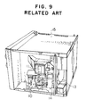
- Fig. 9 illustrates a high frequency heating apparatus body 15 to which an inverter power supply 10, a magnetron 11, a motor 13 and a fan 14 are separately mounted.
- the air stream must cover a substantially large area in order to sufficiently air-cool the inverter power supply 10 and the magnetron 11. Therefore, a propeller fan is employed as the cooling fan 14, which can generate a large air flow.
- An AC motor is employed as the motor 13 to drive the cooling fan 14.
- the forced air cooling is performed by a combination of an AC motor and a propeller fan.
- Such an air cooling system becomes inevitably large.
- Such a conventional high frequency heating apparatus has problems as described below.
- the inverter power supply 10, the motor 13, etc. are separately mounted to the high frequency heating apparatus body 15, many assembly processes are required.
- Lead wires must be used to connect components such as the inverter power supply 10, the motor 13 and the like to the power source in order to supply required powers to the components respectively.
- the inverter power supply 10 and the motor 13 are mounted to the high frequency heating apparatus body 15, they are connected to the power source by the lead wires. Since there is only a small space for the lead wires to be wired, the wiring process is not easy and normally requires manual labor. Also, since the inverter power supply 10, the motor 13, etc., vary in shape and each of them must be wired with lead wires, the assembly processes are hard to automate and simplify.
- the lead wires supplying power to the inverter power supply 10, the motor 13, the magnetron 11, etc. radiate undesirable electromagnetic waves which affect electrical appliances, such as a TV or a radio, placed nearby.
- the semiconductor switching device 6 produces a lot of heat and requires substantially large fins for efficient heat radiation, the large fins take up a large amount of space on the printed board, and thus hinder employing a small and compact printed board.
- U.S. Pat. No. 4,956,531 discloses a power module in which an inverter power supply is placed in a metallic envelope and a magnetron and a fan are compactly combined.
- the three components are separately placed in different casings. Therefore, the three casings must be connected to one another during the assembly of the high frequency heating apparatus. Further, the casing of the magnetron and the casing of the inverter power supply must be connected to the power source by means of lead wires. This wiring process is troublesome. Also, the lead wires used for the connection are likely to radiate undesirable electromagnetic waves (noises).
- the present invention is constructed in order to solve the above-stated problems.
- a high frequency heating apparatus comprises: a power converting unit comprising one or more semiconductor devices; a magnetron which receives the output from the power converting unit and supplies electromagnetic waves to a heating chamber; and a cooling fan for cooling the power converting unit and the magnetron.
- a power converting unit and the magnetron are housed in a case which is made of an electricity-conductive material.
- the air sent from the cooling fan cools at least a portion of the power converting unit before it cools the magnetron.
- a portion or the whole of the fan case of the cooling fan is formed of a cooling member, and a component part of the power converting unit is mounted on the cooling member so as to facilitate cooling of the component part.
- a transformer and a semiconductor switching device which are electric component parts of the power converting unit are arranged upstream of a passage of the cooling air stream generated by the cooling fan.
- the magnetron is placed downstream thereof.
- Such arrangement facilitates reducing the size of the power supply system.
- the magnetron and the electric component parts of the power converting unit can be placed close to one another.
- packaging density can be increased.
- the passage of cooling air does not need to be large, and it is not required that the fan generates a large flow of air.
- the size of the apparatus can be reduced.
- a high frequency heating apparatus comprises: a power converting unit comprising one or more semiconductor devices; a magnetron which receives the output from the power converting unit and supplies electromagnetic waves to a heating chamber; and a cooling fan for cooling the power converting unit and the magnetron.
- a power converting unit comprising one or more semiconductor devices
- a magnetron which receives the output from the power converting unit and supplies electromagnetic waves to a heating chamber
- a cooling fan for cooling the power converting unit and the magnetron.
- At least the power converting unit and the magnetron are housed in a case which is made of an electricity-conductive material.
- the component parts of the power converting unit are mounted on a printed board.
- At least a fan case of the cooling fan is mounted on the printed board.
- a motor for driving the cooling fan is mounted on the printed board.
- the assembly work of the high frequency heating apparatus is simplified.
- the plurality of component parts can be connected to the high frequency heating apparatus by simply mounting the case thereto.
- the case can be formed in a desired shape so as to facilitate automated assembly.
- lead wires are not required in order to connect the component parts with the power source since the power converting unit, the fan case and the motor of the cooling fan are mounted connected to the same printed board.
- the number of the assembly steps can substantially be reduced, and so can be production costs.
- a high frequency heating apparatus comprises: a power converting unit comprising one or more semiconductor devices; a magnetron which receives the output from the power converting unit and supplies electromagnetic waves to a heating chamber; and a cooling fan for cooling the power converting unit and the magnetron. At least the power converting unit and the magnetron are housed in a case which is made of an electricity-conductive material.
- the electricity-conductive case contains the magnetron, the power converting unit, the cooling fan, lead wires for supplying the output of the power converting unit to the magnetron and to the cooling fan.
- Such construction prevents noise radiation from leaking out of the high frequency heating apparatus.
- a high frequency heating apparatus comprises: a power converting unit comprising one or more semiconductor devices; a magnetron which receives the output from the power converting unit and supplies electromagnetic waves to a heating chamber; and a cooling fan for cooling the power converting unit and the magnetron.
- a power converting unit comprising one or more semiconductor devices
- a magnetron which receives the output from the power converting unit and supplies electromagnetic waves to a heating chamber
- a cooling fan for cooling the power converting unit and the magnetron.
- At least the power converting unit and the magnetron are housed in a case which is made of an electricity-conductive material.
- a waveguide is employed to supply electromagnetic waves outputted by the magnetron to the heating chamber, and it is also used to connect the case with the heating chamber.
- a buffer member is placed between the case and a housing.
- the buffer member provided between the case and the housing helps increase the dimensional tolerance of the connecting portions between the case and the waveguide and between the case and the housing. Therefore, even if the housing or the heating chamber is distorted because of assembly deviation or vibrations during transportation, the buffer member absorbs the distortion and prevents it from spreading.
- a high frequency heating apparatus comprises: a power converting unit comprising one or more semiconductor devices; a magnetron which receives the output from the power converting unit and supplies electromagnetic waves to a heating chamber; and a cooling fan for cooling the power converting unit and the magnetron. At least the power converting unit and the magnetron are housed in a case which is made of an electricity-conductive material. The air sent from the cooling fan cools at least a portion of the power converting unit before it cools the magnetron.
- the electric component parts are arranged in a passage of the cooling air, in the manner that a component part which generates less heat is placed further upstream of the passage or in the manner that a component part having a lower endurable temperature is placed further upstream.
- the losses of the main electric component parts of the power converting unit are as follows: the loss of a rectifier is about 15 W; the loss of an inductor about 8 W; the loss of a semiconductor switching device about 40 W; and the loss of a transformer about 15 W.
- the magnetron causes a loss of about 300 W.
- the magnetron which is large in size as well as in loss, substantially heats the cooling air.
- the magnetron is placed upstream, a large flow of cooling air is required in order to sufficiently cool not only the magnetron but also the electric component parts placed downstream, such as the semiconductor switching device, the transformer, etc. In other words, it is required that the motor of the fan be driven substantially fast. Thus, cooling efficiency becomes substantially low. Also, if an electric component part having a higher endurable temperature is placed downstream, an electric component part having a lower endurable temperature can be protected from being exposed to excessively heated air. Thus, the service time thereof is sustained.
- efficient cooling can be performed by arranging the electric component parts in a passage of the cooling air, in the manner that a component part which generates less heat is placed further upstream of the passage or in the manner that a component part having a lower endurable temperature is placed further upstream.
- the fifth object is also achieved by providing a high frequency heating apparatus further comprising a first air guide for guiding air to be used for cooling and a second air guide for guiding air having been used for cooling into the heating chamber.
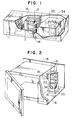
- Fig. 1 is a perspective illustration of a power supply system of a high frequency heating apparatus according to one embodiment of the present invention.
- Fig. 2 is a perspective illustration of the power supply system shown in Fig. 1 when mounted to a housing of a high frequency heating apparatus according to the present invention.
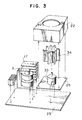
- Fig. 3 is a partial perspective view of a cooling unit of the power supply system shown in Fig. 1.
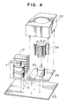
- Fig. 4 is a perspective view of a cooling unit according to another embodiment of the present invention.
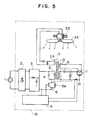
- Fig. 5 is a circuit diagram of the power supply system shown in Fig. 1.
- Fig. 6 is a partial perspective view of a cooling unit according to still another embodiment of the present invention.
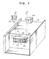
- Fig. 7 is a perspective illustration of a power supply system according to another embodiment of the present invention, when mounted to the housing of a high frequency heating apparatus.
- Fig. 8 is a circuit diagram of a power supply system of a high frequency heating apparatus according to the related art.
- Fig. 9 is a perspective view of a power supply system mounted to a high frequency heating apparatus, according to the related art.
- Fig. 1 shows a power supply system in which the electric component parts are compactly assembled inside a case 16.
- a fan 34 is a sirocco type fan which is highly resistant against pressure damage.
- a motor 33 (not shown) for driving the fan 34 is a DC motor, which produces high speed rotation and contributes to down-sizing.
- the air stream generated by the fan 34 cools a component part of a control circuit which causes a loss of several watts. Then, it cools a transformer 7 and fins 17 attached to a semiconductor switching device (about 40 W loss) and a rectifier (about 15 W loss).
- a magnetron 11 is placed farthest downstream of the passage of the cooling air since it causes a large loss, i.e. about 300 W.
- the magnetron 11 When the magnetron 11 is in normal operation, it is sufficient to cool the anode of the magnetron 11 down to about 180°C or lower. To obtain such a temperature of the anode, the magnetron 11 requires about 0.5 m 3 /min of cooling air of a room temperature. If a fan 34 sends cooling air to the magnetron 11 at a rate of 0.5 m 3 /min in the power supply system, the temperature of cooling air increases by about 10 K before it reaches the magnetron 11 since the cooling air receives heat from the fins 17 and the transformer 7. In practice, therefore, the fan 34 is required to supply the magnetron 11 with cooling air at a rate of a little more than 0.5 m 3 /min. In other words, it is required to increase the rotational speed of the motor.
- the case 16 is made of aluminium and contains electric component parts compactly assembled.
- the electric component parts including the magnetron 11 are arranged in the cooling air passage in an increasing order of generated heat of endurable temperature.
- Such arrangement of the component parts enables efficient air-cooling and contributes to reducing the size of the power supply system.
- the power supply system can be made small enough to be easily mounted to a high frequency heating apparatus, as shown in Fig. 2.
- the case 16 shields noise sources: that is, the magnetron 11; the semiconductor switching device (not shown); the rectifier (not shown), the transformer 7; and the lead wires connecting the magnetron 11 with the transformer 7.
- noise sources that is, the magnetron 11; the semiconductor switching device (not shown); the rectifier (not shown), the transformer 7; and the lead wires connecting the magnetron 11 with the transformer 7.
- the electric component parts are housed in the case 16 so as to shield against the noise radiation from the above mentioned noise sources: that is, the magnetron 11; the semiconductor switching device 6; the rectifier 2; the transformer 7; and the lead wires connecting the magnetron 11 with the transformer 7, a cooling fan 34 is provided inside the case 16, and the electric component parts including the magnetron 11 are arranged in the cooling air passage in an increasing order of generated heat of endurable temperature.
- a cooling fan 34 is provided inside the case 16, and the electric component parts including the magnetron 11 are arranged in the cooling air passage in an increasing order of generated heat of endurable temperature.
- Such arrangement of the component parts enables efficient air-cooling and contributes to reducing the size of the power supply system 18.
- the power supply system 18 can be made small enough to be easily mounted to a high frequency heating apparatus 15.
- Fig. 2 shows a high frequency heating apparatus 15 having an aluminium-made case 16 mounted thereto.
- the high frequency heating apparatus 15 employs a buffer member 20 placed between the case 16 and the bottom board 19 of the apparatus.
- the buffer member 20 is made of an elastic material.
- the case 16 is mounted to the high frequency heating apparatus 15 by connecting the case 16 to a waveguide 21 as well as interposing the buffer member 20 between the case 16 and the bottom board 19.
- the case 16 is connected to the apparatus only by means of the waveguide 21. As a result, all the weight of the case 16 is imposed on the portion of the waveguide 21. Thus, distortion is likely to occur in a connecting portion between the waveguide 21 and the case 16 and/or a connecting portion between the waveguide 21 and the apparatus body. If a substantially large distortion occurs in the connecting portions, it may produce a gap through which microwaves leak.
- the buffer member 20 prevents propagation of vibrations. Without the buffer member 20, the vibration of a cooling fan 34 contained in the case 16 causes resonance, and the vibration of the case 16 propagates to the bottom board 19 of the apparatus body. According to the present invention, the leakage of vibration and noise caused by the vibration to the outside of the apparatus are substantially reduced.
- a plurality of the case 16 of the same construction can be mounted to a variety of models of high frequency heating apparatus, regardless of the construction of an apparatus or the shape of a heating chamber, simply by employing a waveguide 21 suitably made or shaped.
- a waveguide 21 suitably made or shaped.
- the waveguides 21 and the power supply systems 18 housed in the cases 16 can be separately manufactured and then connected on the assembly line. Therefore, a large number of the power supply systems 18 can be manufactured beforehand and stocked.
- Fig. 3 illustrates a method for mounting a fin member 17, a transformer 7, a fan 34 for cooling these electric component parts, a motor 33 for rotating the fan 34, and a fan cover 22, onto a printed board 23.
- the fin member 17 is connected to a semiconductor switching device, which is one of the electric component parts of an inverter power supply.
- the electric component parts, the motor 33, the fan 34 and the fan case cover 22 are mounted to the same surface (the top surface in Fig. 3) of the printed board.
- the electric component parts and the motor 33 can be soldered to the printed board 23 simply by dipping the assembled printed board 23 in a solder bath once.
- the fan 34 is moved down to be mounted to a shaft of the motor 33, and the fan case cover 22 is also moved down for mounting.
- the motor 33, the fan 34 and the fan case cover 22 to the printed board 23 the assembly can be easily automated.
- a DC motor and a sirocco fan are employed in this embodiment to reduce the size of the high frequency heating apparatus.
- a sirocco fan normally provides a higher wind pressure than that of a propeller fan. Therefore, a sirocco fan is more suitable for cooling the printed board 23, in which the packaging density of the component parts is increased in order to reduce the size of the apparatus.
- the DC motor requires a low voltage DC power supply. Therefore, an extra winding 24 is provided in the transformer 7, which is one of the electric component parts of the inverter power supply 18. The low voltage AC power obtained from the winding 24 is rectified in order to provide a low voltage DC power.
- a high frequency heating apparatus does not affect the other electrical appliances such as a TV, a radio, etc.
- Fig. 4 illustrates another mounting method in which a semiconductor switching device 6 is mounted on a fan case 25.
- the fan case 25 includes a table for supporting a motor 33.
- a highly heat-conductive material such as aluminium is used to form the fan case 25 so that the heat generated by the semiconductor switching devide 6 is effectively released through the fan case 25.
- the fan case 25 functions not only as a guide for the air stream generated by a fan 34 but also as a supporting table for the motor 33 and a cooling member for the semiconductor switching device 6. Since an upper portion of the fan case 25 is exposed to a substantially large air flow, heat is effectively released therefrom. Thus, the semiconductor switching device 6 can be effectively cooled.
- Working together with the fan case 25, a fan case cover 22 releases heat.
- a cooling member for a heat-emitting component part such as a semiconductor switching device may be built into a fan case by employing a method other than the method described above with reference to Fig. 4.
- a fan cover 22 is formed by employing cooling members made of, e.g. aluminium for two side walls 22a and 22b thereof and resin-made members for the rest portion 22c thereof.
- a semiconductor switching device 6 and a rectifier 2 are mounted respectively on the two side walls 22a and 22b.
- the assembled fan case cover 22 is mounted on a printed board 23, as shown in Fig. 6.
- the fan case cover 22 may be mounted on the printed board 23, a motor 33 being separately mounted on a case 16 (not shown).
- This construction is suitable for a case where the vibration of the motor 33 is so strong as to possibly cause damage to the printed board 23 or where the motor 33 is an AC motor driven by a commercial power supply 1 (not shown).
- FIG. 7 illustrates the second embodiment of the present invention.
- a power supply system 18 similar to that in the first embodiment further comprises a first air guide 26 for guiding air into the power supply system 18 and a second air guide 27 for guiding air therefrom into a heating chamber. Both the first and second air guides 26 and 27 are removably screwed to the case 16. This construction prevents heated air from being taken in through an inlet provided on the case 16. Heated air is not only let out of the power supply system 18 but exists around the case 18 because of heat-radiation mainly from a magnetron 11. Thus, effective cooling of the power supply system 18 is ensured. Also, since the air which has received heat inside the power supply system 18 is guided through the second air guide 27 into the heating chamber, the heating efficiency of the high frequency heating apparatus is upgraded.
- first and second air guides 26 and 27 are formed separately from the case 16 so as to be removably mounted thereon, a plurality of the cases 16 having the same construction can be employed in differently-designed high frequency heating apparatuses simply by using suitably made first and second air guides 26 and 27. Such a feature substantially helps reduce the number of step which are required for changing the design of an apparatus or for developing the designs for a variety of models thereof.
- first and second air guides 26 and 27 and the power supply systems 18 housed in the cases 16 can be separately manufactured and then connected on the assembly line, a large number of the power supply systems 18 housed in the cases 16 can be manufactured beforehand and stocked.
Applications Claiming Priority (10)
| Application Number | Priority Date | Filing Date | Title |
|---|---|---|---|
| JP72733/91 | 1991-04-05 | ||
| JP72857/91 | 1991-04-05 | ||
| JP7273391A JPH04309720A (ja) | 1991-04-05 | 1991-04-05 | 高周波加熱装置 |
| JP7285791A JPH04308682A (ja) | 1991-04-05 | 1991-04-05 | 高周波加熱装置 |
| JP134007/91 | 1991-06-05 | ||
| JP13400791A JPH04359888A (ja) | 1991-06-05 | 1991-06-05 | 高周波加熱装置 |
| JP191798/91 | 1991-07-31 | ||
| JP19179891A JPH0536474A (ja) | 1991-07-31 | 1991-07-31 | 高周波加熱装置 |
| JP3257498A JPH05101880A (ja) | 1991-10-04 | 1991-10-04 | 高周波加熱装置 |
| JP257498/91 | 1991-10-04 |
Publications (2)
| Publication Number | Publication Date |
|---|---|
| EP0507532A1 true EP0507532A1 (fr) | 1992-10-07 |
| EP0507532B1 EP0507532B1 (fr) | 1997-01-02 |
Family
ID=27524403
Family Applications (1)
| Application Number | Title | Priority Date | Filing Date |
|---|---|---|---|
| EP92302782A Expired - Lifetime EP0507532B1 (fr) | 1991-04-05 | 1992-03-30 | Appareil de chauffage à haute fréquence utilisant une alimentation en courant électrique avec onduleur |
Country Status (7)
| Country | Link |
|---|---|
| US (1) | US5288961A (fr) |
| EP (1) | EP0507532B1 (fr) |
| KR (1) | KR920020988A (fr) |
| AU (1) | AU649798B2 (fr) |
| BR (1) | BR9201178A (fr) |
| CA (1) | CA2064255C (fr) |
| DE (1) | DE69216270T2 (fr) |
Cited By (5)
| Publication number | Priority date | Publication date | Assignee | Title |
|---|---|---|---|---|
| EP1081992A2 (fr) * | 1999-09-02 | 2001-03-07 | Kabushiki Kaisha Toshiba | Circuit, sur lequel sont montés des composants, en partie moulés dans une résine recouvant les pistes et les composants internes |
| US6370895B1 (en) | 1999-09-21 | 2002-04-16 | Kabushiki Kaisha Toshiba | Refrigerator with two evaporators |
| WO2003088728A1 (fr) * | 2002-04-12 | 2003-10-23 | Bombardier Transportation Gmbh | Module de conversion de puissance |
| WO2004093498A1 (fr) * | 2003-04-11 | 2004-10-28 | Matsushita Electric Industrial Co. Ltd. | Appareil de chauffage a hautes frequences |
| EP1220576A3 (fr) * | 2000-12-28 | 2006-10-18 | Lg Electronics Inc. | Disppositif de refroidissement d'équipement électrique dans un four à micro-ondes équipé d'un évacuateur d'air |
Families Citing this family (9)
| Publication number | Priority date | Publication date | Assignee | Title |
|---|---|---|---|---|
| US5441102A (en) * | 1994-01-26 | 1995-08-15 | Sun Microsystems, Inc. | Heat exchanger for electronic equipment |
| US5852332A (en) * | 1996-09-09 | 1998-12-22 | Sheer Power Source, Inc. | Sheer power source |
| JPH11214874A (ja) * | 1998-01-22 | 1999-08-06 | Matsushita Electric Ind Co Ltd | 電子機器の冷却装置 |
| JP4386219B2 (ja) * | 2000-03-31 | 2009-12-16 | 富士通株式会社 | 放熱機構及び当該放熱機構を有する電子機器 |
| KR100422037B1 (ko) * | 2001-08-09 | 2004-03-12 | 삼성전기주식회사 | 광경로 변환형 가변 광학 감쇠기 |
| US7474533B2 (en) * | 2001-09-17 | 2009-01-06 | Fujitsu Limited | Cooling device capable of reducing thickness of electronic apparatus |
| JP3973864B2 (ja) * | 2001-09-17 | 2007-09-12 | 富士通株式会社 | 冷却装置付きプリント基板ユニットおよび電子機器 |
| KR100420764B1 (ko) * | 2002-01-17 | 2004-03-02 | 미래산업 주식회사 | 반도체 소자 테스트 핸들러의 냉각유체 공급 제어장치수납박스 |
| JP2013032872A (ja) * | 2011-08-01 | 2013-02-14 | Sharp Corp | 加熱調理器 |
Citations (5)
| Publication number | Priority date | Publication date | Assignee | Title |
|---|---|---|---|---|
| US3129312A (en) * | 1960-03-04 | 1964-04-14 | Husqvarna Vapenfabriks Ab | Apparatus for dielectric heating |
| DE2925338A1 (de) * | 1978-06-26 | 1980-01-10 | Sharp Kk | Kochgeraet |
| US4314126A (en) * | 1978-06-13 | 1982-02-02 | Matsushita Electric Industrial Co., Ltd. | Microwave heating apparatus with cooling conduit |
| US4812617A (en) * | 1979-03-06 | 1989-03-14 | Sharp Kabushiki Kaisha | Cooling system for cooling electrical parts for microwave oven |
| US4956531A (en) * | 1988-07-06 | 1990-09-11 | U.S. Philips Corporation | Microwave oven with adaptable power module |
Family Cites Families (11)
| Publication number | Priority date | Publication date | Assignee | Title |
|---|---|---|---|---|
| US4100463A (en) * | 1975-11-05 | 1978-07-11 | Hitachi, Ltd. | Magnetron, power supply, and fan integral assembly |
| US4131779A (en) * | 1976-07-07 | 1978-12-26 | Hitachi Heating Appliances Co., Ltd. | High-frequency heating apparatus |
| JPS5426147U (fr) * | 1977-07-25 | 1979-02-20 | ||
| US4184945A (en) * | 1978-06-12 | 1980-01-22 | Litton Systems, Inc. | Microwave wall oven air flow system |
| DE2934163C3 (de) * | 1978-09-02 | 1982-01-21 | Tokyo Shibaura Denki K.K., Kawasaki, Kanagawa | Einbau-Mikrowellenherd |
| JPS5843703Y2 (ja) * | 1979-05-01 | 1983-10-03 | リンナイ株式会社 | 複合調理器 |
| US4296297A (en) * | 1979-12-26 | 1981-10-20 | General Electric Company | Drive arrangement for microwave oven mode stirrer |
| CA1213002A (fr) * | 1983-02-16 | 1986-10-21 | Takao Nakanishi | Mecanisme de soupape pour appareil de chauffage ou appareil similaire |
| JPS617892U (ja) * | 1984-06-19 | 1986-01-17 | シャープ株式会社 | 高周波加熱装置 |
| GB2174876B (en) * | 1985-03-14 | 1988-04-20 | Toshiba Kk | Microwave oven |
| JPH04121991A (ja) * | 1990-09-11 | 1992-04-22 | Matsushita Electric Ind Co Ltd | 高周波加熱装置 |
-
1992
- 1992-03-27 US US07/858,525 patent/US5288961A/en not_active Expired - Lifetime
- 1992-03-27 CA CA002064255A patent/CA2064255C/fr not_active Expired - Fee Related
- 1992-03-30 DE DE69216270T patent/DE69216270T2/de not_active Expired - Fee Related
- 1992-03-30 EP EP92302782A patent/EP0507532B1/fr not_active Expired - Lifetime
- 1992-04-01 AU AU13958/92A patent/AU649798B2/en not_active Ceased
- 1992-04-02 BR BR929201178A patent/BR9201178A/pt not_active IP Right Cessation
- 1992-04-03 KR KR1019920005604A patent/KR920020988A/ko not_active Application Discontinuation
Patent Citations (5)
| Publication number | Priority date | Publication date | Assignee | Title |
|---|---|---|---|---|
| US3129312A (en) * | 1960-03-04 | 1964-04-14 | Husqvarna Vapenfabriks Ab | Apparatus for dielectric heating |
| US4314126A (en) * | 1978-06-13 | 1982-02-02 | Matsushita Electric Industrial Co., Ltd. | Microwave heating apparatus with cooling conduit |
| DE2925338A1 (de) * | 1978-06-26 | 1980-01-10 | Sharp Kk | Kochgeraet |
| US4812617A (en) * | 1979-03-06 | 1989-03-14 | Sharp Kabushiki Kaisha | Cooling system for cooling electrical parts for microwave oven |
| US4956531A (en) * | 1988-07-06 | 1990-09-11 | U.S. Philips Corporation | Microwave oven with adaptable power module |
Cited By (8)
| Publication number | Priority date | Publication date | Assignee | Title |
|---|---|---|---|---|
| EP1081992A2 (fr) * | 1999-09-02 | 2001-03-07 | Kabushiki Kaisha Toshiba | Circuit, sur lequel sont montés des composants, en partie moulés dans une résine recouvant les pistes et les composants internes |
| EP1081992A3 (fr) * | 1999-09-02 | 2001-10-10 | Kabushiki Kaisha Toshiba | Circuit, sur lequel sont montés des composants, en partie moulés dans une résine recouvant les pistes et les composants internes |
| US7203071B2 (en) | 1999-09-02 | 2007-04-10 | Kabushiki Kaisha Toshiba | Component mounting circuit board with resin-molded section covering circuit pattern and inner components |
| US6370895B1 (en) | 1999-09-21 | 2002-04-16 | Kabushiki Kaisha Toshiba | Refrigerator with two evaporators |
| EP1220576A3 (fr) * | 2000-12-28 | 2006-10-18 | Lg Electronics Inc. | Disppositif de refroidissement d'équipement électrique dans un four à micro-ondes équipé d'un évacuateur d'air |
| WO2003088728A1 (fr) * | 2002-04-12 | 2003-10-23 | Bombardier Transportation Gmbh | Module de conversion de puissance |
| WO2004093498A1 (fr) * | 2003-04-11 | 2004-10-28 | Matsushita Electric Industrial Co. Ltd. | Appareil de chauffage a hautes frequences |
| US7414228B2 (en) | 2003-04-11 | 2008-08-19 | Matsushita Electric Industrial Co., Ltd. | High frequency heating apparatus |
Also Published As
| Publication number | Publication date |
|---|---|
| EP0507532B1 (fr) | 1997-01-02 |
| CA2064255C (fr) | 1997-10-21 |
| AU649798B2 (en) | 1994-06-02 |
| DE69216270T2 (de) | 1997-07-17 |
| KR920020988A (ko) | 1992-11-21 |
| CA2064255A1 (fr) | 1992-10-06 |
| AU1395892A (en) | 1992-10-15 |
| DE69216270D1 (de) | 1997-02-13 |
| BR9201178A (pt) | 1992-12-01 |
| US5288961A (en) | 1994-02-22 |
Similar Documents
| Publication | Publication Date | Title |
|---|---|---|
| US5288961A (en) | High frequency heating apparatus utilizing an inverter power supply | |
| US20070158341A1 (en) | Transformer assembly for microwave oven, method for manufacturing the same, and microwave oven having the same | |
| EP0493604B1 (fr) | Appareil de chauffage a haute frequence utilisant une alimentation en courant du type a commutation pour magnetron | |
| JP3477085B2 (ja) | 高周波加熱装置用インバータ電源 | |
| KR970000099Y1 (ko) | 인버어터전원을 사용한 고주파가열장치 | |
| JPH05326132A (ja) | 高周波加熱装置 | |
| JP3087513B2 (ja) | 高周波加熱装置 | |
| JPH0787739A (ja) | スイッチング電源装置 | |
| CN1026847C (zh) | 采用换流器电源的高频加热装置 | |
| JP6379353B2 (ja) | Dc−dcコンバータ | |
| JP2563566B2 (ja) | 高周波加熱装置 | |
| JP4779245B2 (ja) | インバータ装置 | |
| JPH04309720A (ja) | 高周波加熱装置 | |
| JP3468019B2 (ja) | 高周波加熱装置の電源用高圧回路 | |
| CN212276973U (zh) | 一种大功率高频开关电源变压器冷却装置 | |
| JP3677175B2 (ja) | 電子レンジ | |
| JP2538445B2 (ja) | 高周波加熱装置 | |
| JP2004241311A (ja) | 高周波加熱装置 | |
| JPH0246692A (ja) | 高周波加熱装置 | |
| KR970005101B1 (ko) | 전자렌지 전자파 차폐장치 | |
| JPH0533946A (ja) | 高周波加熱装置 | |
| JPS6136622A (ja) | 高周波加熱装置 | |
| JPS63150880A (ja) | 高周波加熱装置 | |
| JP2004198078A (ja) | 高周波加熱装置 | |
| JPH049528A (ja) | 高周波加熱装置 |
Legal Events
| Date | Code | Title | Description |
|---|---|---|---|
| PUAI | Public reference made under article 153(3) epc to a published international application that has entered the european phase |
Free format text: ORIGINAL CODE: 0009012 |
|
| AK | Designated contracting states |
Kind code of ref document: A1 Designated state(s): DE FR GB IT SE |
|
| 17P | Request for examination filed |
Effective date: 19921030 |
|
| 17Q | First examination report despatched |
Effective date: 19940616 |
|
| GRAG | Despatch of communication of intention to grant |
Free format text: ORIGINAL CODE: EPIDOS AGRA |
|
| GRAH | Despatch of communication of intention to grant a patent |
Free format text: ORIGINAL CODE: EPIDOS IGRA |
|
| GRAH | Despatch of communication of intention to grant a patent |
Free format text: ORIGINAL CODE: EPIDOS IGRA |
|
| GRAA | (expected) grant |
Free format text: ORIGINAL CODE: 0009210 |
|
| STAA | Information on the status of an ep patent application or granted ep patent |
Free format text: STATUS: THE PATENT HAS BEEN GRANTED |
|
| ITF | It: translation for a ep patent filed |
Owner name: BARZANO' E ZANARDO ROMA S.P.A. |
|
| AK | Designated contracting states |
Kind code of ref document: B1 Designated state(s): DE FR GB IT SE |
|
| REF | Corresponds to: |
Ref document number: 69216270 Country of ref document: DE Date of ref document: 19970213 |
|
| ET | Fr: translation filed | ||
| PLBE | No opposition filed within time limit |
Free format text: ORIGINAL CODE: 0009261 |
|
| 26N | No opposition filed | ||
| REG | Reference to a national code |
Ref country code: GB Ref legal event code: IF02 |
|
| PGFP | Annual fee paid to national office [announced via postgrant information from national office to epo] |
Ref country code: GB Payment date: 20090325 Year of fee payment: 18 |
|
| PGFP | Annual fee paid to national office [announced via postgrant information from national office to epo] |
Ref country code: DE Payment date: 20090327 Year of fee payment: 18 Ref country code: SE Payment date: 20090306 Year of fee payment: 18 Ref country code: IT Payment date: 20090321 Year of fee payment: 18 |
|
| PGFP | Annual fee paid to national office [announced via postgrant information from national office to epo] |
Ref country code: FR Payment date: 20090316 Year of fee payment: 18 |
|
| EUG | Se: european patent has lapsed | ||
| GBPC | Gb: european patent ceased through non-payment of renewal fee |
Effective date: 20100330 |
|
| REG | Reference to a national code |
Ref country code: FR Ref legal event code: ST Effective date: 20101130 |
|
| PG25 | Lapsed in a contracting state [announced via postgrant information from national office to epo] |
Ref country code: FR Free format text: LAPSE BECAUSE OF NON-PAYMENT OF DUE FEES Effective date: 20100331 |
|
| PG25 | Lapsed in a contracting state [announced via postgrant information from national office to epo] |
Ref country code: DE Free format text: LAPSE BECAUSE OF NON-PAYMENT OF DUE FEES Effective date: 20101001 |
|
| PG25 | Lapsed in a contracting state [announced via postgrant information from national office to epo] |
Ref country code: IT Free format text: LAPSE BECAUSE OF NON-PAYMENT OF DUE FEES Effective date: 20100330 Ref country code: GB Free format text: LAPSE BECAUSE OF NON-PAYMENT OF DUE FEES Effective date: 20100330 |
|
| PG25 | Lapsed in a contracting state [announced via postgrant information from national office to epo] |
Ref country code: SE Free format text: LAPSE BECAUSE OF NON-PAYMENT OF DUE FEES Effective date: 20100331 |