EP0507331A1 - Verfahren zum Herstellen eines länglichen unterirdischen Grossraumes von quadratischem oder rechteckigem Querschnitt - Google Patents
Verfahren zum Herstellen eines länglichen unterirdischen Grossraumes von quadratischem oder rechteckigem Querschnitt Download PDFInfo
- Publication number
- EP0507331A1 EP0507331A1 EP92105799A EP92105799A EP0507331A1 EP 0507331 A1 EP0507331 A1 EP 0507331A1 EP 92105799 A EP92105799 A EP 92105799A EP 92105799 A EP92105799 A EP 92105799A EP 0507331 A1 EP0507331 A1 EP 0507331A1
- Authority
- EP
- European Patent Office
- Prior art keywords
- square
- shell
- lateral
- rectangular
- units
- Prior art date
- Legal status (The legal status is an assumption and is not a legal conclusion. Google has not performed a legal analysis and makes no representation as to the accuracy of the status listed.)
- Granted
Links
- 238000004519 manufacturing process Methods 0.000 title claims abstract description 13
- 239000002689 soil Substances 0.000 claims abstract description 21
- 239000011150 reinforced concrete Substances 0.000 claims description 4
- 239000004567 concrete Substances 0.000 description 10
- 239000004570 mortar (masonry) Substances 0.000 description 6
- 238000000034 method Methods 0.000 description 5
- 229910000831 Steel Inorganic materials 0.000 description 4
- 239000000945 filler Substances 0.000 description 4
- 239000010959 steel Substances 0.000 description 4
- 230000015572 biosynthetic process Effects 0.000 description 1
- 238000007796 conventional method Methods 0.000 description 1
- 238000007599 discharging Methods 0.000 description 1
- 239000011440 grout Substances 0.000 description 1
- 239000000463 material Substances 0.000 description 1
- 238000007790 scraping Methods 0.000 description 1
Images


Classifications
-
- E—FIXED CONSTRUCTIONS
- E21—EARTH OR ROCK DRILLING; MINING
- E21D—SHAFTS; TUNNELS; GALLERIES; LARGE UNDERGROUND CHAMBERS
- E21D13/00—Large underground chambers; Methods or apparatus for making them
-
- E—FIXED CONSTRUCTIONS
- E21—EARTH OR ROCK DRILLING; MINING
- E21D—SHAFTS; TUNNELS; GALLERIES; LARGE UNDERGROUND CHAMBERS
- E21D9/00—Tunnels or galleries, with or without linings; Methods or apparatus for making thereof; Layout of tunnels or galleries
- E21D9/06—Making by using a driving shield, i.e. advanced by pushing means bearing against the already placed lining
- E21D9/08—Making by using a driving shield, i.e. advanced by pushing means bearing against the already placed lining with additional boring or cutting means other than the conventional cutting edge of the shield
- E21D9/0875—Making by using a driving shield, i.e. advanced by pushing means bearing against the already placed lining with additional boring or cutting means other than the conventional cutting edge of the shield with a movable support arm carrying cutting tools for attacking the front face, e.g. a bucket
- E21D9/0879—Making by using a driving shield, i.e. advanced by pushing means bearing against the already placed lining with additional boring or cutting means other than the conventional cutting edge of the shield with a movable support arm carrying cutting tools for attacking the front face, e.g. a bucket the shield being provided with devices for lining the tunnel, e.g. shuttering
Definitions
- the present invention relates to a method of making a huge underground space whose size is comparable to a town or city space.
- Japanese Patent 3-39,600(A) shows a method of making such a huge underground space, which is illustrated in Fig.19.
- Fig.20 shows the manner in which a huge underground space is made.
- a shield driving machine M is driven in one direction from one longitudinal hole to the other longitudinal hole to make one lateral sector shell-unit S having passage P therein extending between the opposite longitudinal holes.
- the shield driving machine M is driven in the other direction from the other longitudinal hole to the one longitudinal hole to make another lateral sector shell-unit S running adjoiningly and parallel to the first lateral shell-unit.
- This lateral shell-unit making process is repeated until a plurality of lateral shell-units are continuously arranged on the circumference of a huge circle, thus forming the outer shell of the huge underground space. Then, the lateral shell-unit making process is repeated until a plurality of lateral shell-units are continuously arranged on a horizontal chord.
- the soil is removed from the major and minor segments of the huge circle which are delimited by the outer shell.
- the object of the present invention is to provide a method of making such a huge underground space with ease and efficiency.
- a first method of making a huge elongated space of square or rectangular cross section under the ground comprises the steps of: making at least two longitudinal holes at an elongated interval in the earth; making a plurality of first lateral square or rectangular shell-units having shielded passages therein extending between said longitudinal holes and arranged at regular intervals on the four sides of a square or rectangular shape corresponding to the square or rectangular cross section of said huge elongated space; making a plurality of second lateral square or rectangular shell-units having shielded passages extending between said longitudinal holes and arranged on the four sides of said square or rectangular shape for each second lateral square or rectangular shell-unit to occupy the interval and connect adjacent first lateral square or rectangular shell-units to form a continuous huge square or rectangular elongated outer-shell; and removing the soil from the square or rectangular area delimited by said huge outer shell to leave the huge elongated space extending between said longitudinal holes.
- Two or more parallel-connected shield driving machines each having a same size and square or rectangular shape, may be used to make each of said first and second lateral square or rectangular shell-units.
- a second method of making a huge elongated space of square or rectangular cross section under the ground comprises the steps of: making at least two longitudinal holes at an elongated interval in the earth; making a plurality of first lateral square or rectangular shell-units having shielded passages extending between said longitudinal holes and arranged at intervals on the four sides of a square or rectangular shape corresponding to the square or rectangular cross section of said huge elongated space; making a plurality of second lateral square or rectangular shell-units having shielded passages extending between said longitudinal holes and arranged on the four sides of said square or rectangular shape so as to position each second lateral shell-unit between adjacent first lateral shell-units, leaving soil between said first and second lateral shell-units; forming reinforced concrete structures to connect adjacent first and second lateral shell-units to form a continuous huge square or rectangular elongated outer-shell; and removing the soil from the square or rectangular area delimited by said outer shell thus connected to leave the huge elongated space extending between said longitudinal
- Two or more parallel-connected shield driving machines each having a different size and square or rectangular shape, may be used to make each of said first and second lateral square or rectangular shell-units.
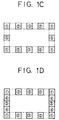
- FIG.1 there is shown a method of making a huge elongated space of rectangular cross section under the ground according to the invention.
- two longitudinal holes 1 and 2 (Fig.6) are made at an elongated interval in the earth.
- a plurality of first lateral square shell-units 1, 2 and 3 (Fig.1C) each forming a shielded passage therein are made at regular intervals on the four sides of a rectangular shape (broken lines) corresponding to the rectangular cross section of the huge elongated space to be made.
- proximal-to-distal end direction four square shield driving machines (Figs.8, 9 and 10) are driven from one longitudinal hole 1 to the other longitudinal hole 2 in one direction (hereinafter referred to as the "proximal-to-distal end direction") to make four lateral shell-units 1, 1, 1 and 1 at the four corners of the huge rectangular shell shape (Fig.1A).
- these four shield driving machines are driven from the other longitudinal hole 2 to the one longitudinal hole 1 in the other or opposite direction (hereinafter referred to as the "distal-to-proximal end direction") to make four lateral shell-units 2, 2, 2 and 2 apart from each corner square shell-units 1, 1, 1 and 1 by the distance of one side of the square unitary hole (Fig.1B).
- the four shield driving machines are driven in the "proximal-to-distal end direction” to make four lateral shell-units 3, 3, 3 and 3 apart from each of the four corner square shell-units 1 and each of the four square shell-units 2 by the distance of one side of the unitary square hole (Fig.1C).
- the four shield driving machines are driven in the "distal-to-proximal end direction” to make four lateral shielded square shell-units 4, 4, 4 and 4 to connect each of the corner square shell-units 1, 1, 1 and 1 and the intermediate lateral shell-unit 3, thus making up two opposite vertical stretches (Fig.1D).
- the four shield driving machines are driven in the "proximal-to-distal end direction” to make four lateral shell-units 5, 5, 5 and 5 to connect each of the corner shell-units 1, 1, 1 and 1 and the lateral shell-units 2, 2, 2 and 2 (Fig.1E).
- the four shield driving machines are driven in the "distal-to-proximal end direction” to make four lateral shell-units 6, 6, 6 and 6 to connect the lateral shell-units 2, 2, 2 and 2 and 3, 3, 3 and 3, thus making up upper and lower horizontal stretches (Fig.1F).
- These lateral shell-units 1 to 6 run parallel from one longitudinal hole 1 to the other longitudinal hole 2 under the ground to make up the outer shell of the huge underground space.
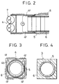
- a shield driving machine 4 which is described later in detail, makes a lateral hole, starting from one longitudinal hole and advancing towards the other longitudinal hole.
- the shield driving machine 4 rotates its front cutters 7 to remove the soil in front of the machine, pushing the removed soil behind.
- Steel or concrete sector segments 5 as lining material are brought in the hole thus made, and these sector segments 5 are arranged to form an inner circular shell.
- An associated pump P is used to feed filler or grout such as formed mortar or concrete via its feeding pipes 4f into the circumferential space between the inner circular shell and the lateral hole, as indicated at 6 to make a square lateral shell-unit 3 as seen in Fig.4.
- a lateral shell-units 3 having shielded passage therein is made so as to integrally connected to adjacent lateral shell-units 3A, 3B.
- a shield driving machine is made to advance, thus making a lateral hole, and at the same time cutting and scraping the side surface of the filler of each of the opposite shell-units 4, thus exposing the fresh jagged mortar or concrete surface over the side of each shell-units 3A and 3B.
- Steel or concrete sector segments 5 are brought in the hole thus made, and these sector segments 5 are arranged to form an inner circular shell, as described earlier.
- Fig.6 shows, in cross section, the underground space delimited by the continuous outer shell made of horizontal and vertical integral arrangement of lateral shell-units.
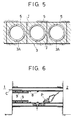
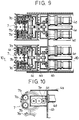
- a shield-driving machine 4 is shown as comprising, in combination, four square-shaped cutters 7 each consisting of two opposite rotary drum cutters 7a and 7a and upper and lower rotary ring cutters 7b and 7b between the opposite rotary drum cutters (Fig.8).
- the shield-driving machine 4 has four motors 4d and associated ganged gearings. Driving power can be transmitted from the motors 4d to the square-shaped cutters 7 via the ganged gearings, which can rotate the rotary drum cutters 7a and 7a and the upper and lower rotary ring cutters 7b and 7b in same direction. These ganged gearings are contained in a gear box 4c.
- the gear box 4b is attached to a transverse wall 4b, which divides the space of casing 4a into the motor compartment and the gearing compartment. Mud discharging conduits 4e extend backward below from the drum cutters 7a.
- shield-driving machines 4 are used. It, however, should be understood that an appropriate number of machines may be used in consideration of the size of the underground space to be made, and that shield-driving machines of different shapes and sizes may be combined when occasions demand.
- FIG.11A to 11D there is shown another method of making a huge elongated space of rectangular cross section under the ground according to the invention.
- two longitudinal holes 11 and 12 (Fig.18) are made at an elongated interval in the earth.
- a plurality of first lateral square and rectangular shell-units (Fig.11D) are made at different intervals on the four sides and one intermediate bridge of a rectangular shape corresponding to the rectangular cross section of the huge elongated space which is to be made.
- proximal-to-distal end direction four shield driving machines of different square or rectangular sizes are moved from one longitudinal hole 11 to the other longitudinal hole 12 in one direction (hereinafter referred to as the "proximal-to-distal end direction") to make four lateral square and rectangular shell-units 1 -1, 2 -1, 3 -1 and 4 -1 on selected three sides of the presumed huge rectangular shell shape (broken line in Fig.11A).
- these four shield driving machines are driven from the other longitudinal hole 12 to the one longitudinal hole 11 in the other or opposite direction (hereinafter referred to as the "distal-to-proximal end direction") to make four lateral shell-units 1 -2, 2 -2, 3 -2 and 4 -2 as shown in Fig.11B.
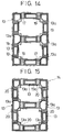
- a bridging hole 17 is made between adjacent lateral square shell-units 13 and 13 by making holes on the side walls of each of the adjacent lateral passages 13a and 13a and removing soil, as shown in Fig.13.
- a plurality of reinforced steel bars 19 extend across each bridging hole 17 (Fig.14), and the bridging hole 17 is filled with concrete 20 (Fig.15).
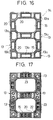
- all lateral shell-units 13 are integrally connected together to form continuous outer shell 14. Then, the soil is removed from each of the upper and lower rectangular areas 15, and the projecting corners of the shell structure are removed.
- Fig.18 power shovels P remove the soil or mud from the rectangular area delimited by the intermediate and lower horizontal and opposite vertical stretches to leave a huge elongated space between the longitudinal holes 11 and 12.
- Beams 8 are fixed to the intermediate horizontal stretch at predetermined intervals to support its weight.
- Frames 9 are made, and concrete is fed via feeding pipes C into the space in the frame 9.
- Selected lateral passages 13a of shell units 13 and trucks T may be used to carry out the soil or mud removed by power shovels P.
- the soil or mud is removed from the area delimited by the intermediate and upper horizontal stretches and by the opposite vertical stretches to leave a huge elongated space between the longitudinal holes 11 and 12.
- Fig.17 shows, in cross section, the underground space delimited horizontal and vertical integral-arrangement of lateral shell-units, which are equipped with pipings 22, air ducts 23 and other necessary equipments.
- underground towns can be built without requiring any large-scale equipments on the ground.
- the huge outer shell can be made with accuracy and efficiency by skiving and jointing adjacent parallel lateral shell-units and by using selected lateral passages formed in the shell-units to discharge the soil or mud removed in making the underground space.
Landscapes
- Engineering & Computer Science (AREA)
- Mining & Mineral Resources (AREA)
- Life Sciences & Earth Sciences (AREA)
- General Life Sciences & Earth Sciences (AREA)
- Geochemistry & Mineralogy (AREA)
- Geology (AREA)
- Environmental & Geological Engineering (AREA)
- Excavating Of Shafts Or Tunnels (AREA)
- Lining And Supports For Tunnels (AREA)
- Superconductors And Manufacturing Methods Therefor (AREA)
- Bulkheads Adapted To Foundation Construction (AREA)
Applications Claiming Priority (6)
| Application Number | Priority Date | Filing Date | Title |
|---|---|---|---|
| JP3099805A JPH0823266B2 (ja) | 1991-04-05 | 1991-04-05 | 地下空間体の構築工法 |
| JP99804/91 | 1991-04-05 | ||
| JP3099804A JPH0819825B2 (ja) | 1991-04-05 | 1991-04-05 | 地下空間体の構築工法 |
| JP99803/91 | 1991-04-05 | ||
| JP99805/91 | 1991-04-05 | ||
| JP3099803A JPH0819824B2 (ja) | 1991-04-05 | 1991-04-05 | 地下空間体の構築工法 |
Publications (2)
| Publication Number | Publication Date |
|---|---|
| EP0507331A1 true EP0507331A1 (de) | 1992-10-07 |
| EP0507331B1 EP0507331B1 (de) | 1996-07-17 |
Family
ID=27309051
Family Applications (1)
| Application Number | Title | Priority Date | Filing Date |
|---|---|---|---|
| EP92105799A Expired - Lifetime EP0507331B1 (de) | 1991-04-05 | 1992-04-03 | Verfahren zum Herstellen eines länglichen unterirdischen Grossraumes von quadratischem oder rechteckigem Querschnitt |
Country Status (4)
| Country | Link |
|---|---|
| US (1) | US5211507A (de) |
| EP (1) | EP0507331B1 (de) |
| AT (1) | ATE140512T1 (de) |
| DE (1) | DE69212193T2 (de) |
Cited By (5)
| Publication number | Priority date | Publication date | Assignee | Title |
|---|---|---|---|---|
| WO2001002692A1 (en) * | 1999-07-02 | 2001-01-11 | Heerema Holding Construction Inc. | Jet excavating device |
| NL1016917C2 (nl) * | 1999-07-02 | 2002-10-08 | Heerema Holding Construction I | Jetgraafinrichting. |
| NL1016952C2 (nl) * | 1999-07-02 | 2002-10-15 | Heerema Holding Construction I | Jetgraafinrichting. |
| JP2015135018A (ja) * | 2014-01-17 | 2015-07-27 | ジャパントンネルシステムズ株式会社 | 合体型掘進機及びこれを用いた掘進方法並びにトンネル構築方法 |
| JP2016132945A (ja) * | 2015-01-21 | 2016-07-25 | 戸田建設株式会社 | 鋼殻エレメントの発進装置及びそれを用いた鋼殻エレメントの発進方向の調整方法 |
Families Citing this family (5)
| Publication number | Priority date | Publication date | Assignee | Title |
|---|---|---|---|---|
| JPH06117187A (ja) * | 1992-10-08 | 1994-04-26 | Iseki Tory Tech Inc | シールド掘削機 |
| JP6901889B2 (ja) * | 2017-03-30 | 2021-07-14 | 戸田建設株式会社 | 外殻先行トンネル構築方法 |
| CN111411977A (zh) * | 2020-03-26 | 2020-07-14 | 中铁十二局集团有限公司 | 单洞双层隧道中隔板模筑衔接施工方法 |
| GB2595270B (en) | 2020-05-20 | 2022-09-28 | Namaya Ltd | Systems and methods of constructing intake-output assemblies for water desalination plants |
| GB2595716A (en) | 2020-06-04 | 2021-12-08 | Namaya Ltd | Systems assemblies and methods of pipe ramming prefabricated members with a structured layout |
Citations (3)
| Publication number | Priority date | Publication date | Assignee | Title |
|---|---|---|---|---|
| CH445549A (de) * | 1967-02-22 | 1967-10-31 | Prader Ag | Verfahren zum Erstellen unterirdischer Hohlräume von grossem Querschnitt |
| US4166509A (en) * | 1976-08-20 | 1979-09-04 | Japanese National Railways | Process for excavating and constructing tunnel and excavating device |
| JPH0339600A (ja) * | 1989-07-04 | 1991-02-20 | Toda Constr Co Ltd | 地下構造物及びその構築工法 |
Family Cites Families (4)
| Publication number | Priority date | Publication date | Assignee | Title |
|---|---|---|---|---|
| US3631680A (en) * | 1968-06-25 | 1972-01-04 | Tube Headings Ltd | Construction of tunnels |
| ES414134A1 (es) * | 1973-04-27 | 1976-02-01 | Mackina Westfalia S A | Procedimiento y dispositivo para la construccion frontal detuneles. |
| US3968655A (en) * | 1973-07-13 | 1976-07-13 | Mcglothlin William K | Method of reinforcing tunnels before excavation |
| JPS5397235A (en) * | 1977-02-05 | 1978-08-25 | Dowa Mining Co | Method of excavating rectangular tunnel |
-
1992
- 1992-04-03 AT AT92105799T patent/ATE140512T1/de not_active IP Right Cessation
- 1992-04-03 DE DE69212193T patent/DE69212193T2/de not_active Expired - Fee Related
- 1992-04-03 EP EP92105799A patent/EP0507331B1/de not_active Expired - Lifetime
- 1992-04-03 US US07/862,944 patent/US5211507A/en not_active Expired - Lifetime
Patent Citations (3)
| Publication number | Priority date | Publication date | Assignee | Title |
|---|---|---|---|---|
| CH445549A (de) * | 1967-02-22 | 1967-10-31 | Prader Ag | Verfahren zum Erstellen unterirdischer Hohlräume von grossem Querschnitt |
| US4166509A (en) * | 1976-08-20 | 1979-09-04 | Japanese National Railways | Process for excavating and constructing tunnel and excavating device |
| JPH0339600A (ja) * | 1989-07-04 | 1991-02-20 | Toda Constr Co Ltd | 地下構造物及びその構築工法 |
Cited By (6)
| Publication number | Priority date | Publication date | Assignee | Title |
|---|---|---|---|---|
| WO2001002692A1 (en) * | 1999-07-02 | 2001-01-11 | Heerema Holding Construction Inc. | Jet excavating device |
| US6385868B2 (en) | 1999-07-02 | 2002-05-14 | Heerema Holding Construction Inc. | Jet excavating device |
| NL1016917C2 (nl) * | 1999-07-02 | 2002-10-08 | Heerema Holding Construction I | Jetgraafinrichting. |
| NL1016952C2 (nl) * | 1999-07-02 | 2002-10-15 | Heerema Holding Construction I | Jetgraafinrichting. |
| JP2015135018A (ja) * | 2014-01-17 | 2015-07-27 | ジャパントンネルシステムズ株式会社 | 合体型掘進機及びこれを用いた掘進方法並びにトンネル構築方法 |
| JP2016132945A (ja) * | 2015-01-21 | 2016-07-25 | 戸田建設株式会社 | 鋼殻エレメントの発進装置及びそれを用いた鋼殻エレメントの発進方向の調整方法 |
Also Published As
| Publication number | Publication date |
|---|---|
| EP0507331B1 (de) | 1996-07-17 |
| ATE140512T1 (de) | 1996-08-15 |
| US5211507A (en) | 1993-05-18 |
| DE69212193D1 (de) | 1996-08-22 |
| DE69212193T2 (de) | 1996-11-28 |
Similar Documents
| Publication | Publication Date | Title |
|---|---|---|
| US5211507A (en) | Method of making a huge elongated space of square or rectangular cross section under the ground | |
| GB1590346A (en) | Process for excavating and constructing tunnel | |
| JP4471521B2 (ja) | シールド工法、大断面トンネルおよびその施工方法並びにシールド掘進機 | |
| JP4556786B2 (ja) | シールド機の推進工法 | |
| JP3088929B2 (ja) | 地下構造物の築造方法 | |
| KR970007379B1 (ko) | 오픈쉴드공법 및 거기에 사용되는 오픈쉴드기 | |
| JPH0781489B2 (ja) | トンネル築造方法および装置 | |
| JP4319064B2 (ja) | 分割函体及び大断面トンネルの施工方法 | |
| JP6309770B2 (ja) | 合体型掘進機及びこれを用いた掘進方法並びにトンネル構築方法 | |
| JP2617418B2 (ja) | 地下大空間構造物の築造方法 | |
| JPH0643796B2 (ja) | シールド機 | |
| JPH0654016B2 (ja) | 地下空間築造工法 | |
| JP7504841B2 (ja) | トンネル函体群ユニットとその施工方法 | |
| JPH04309694A (ja) | 地下空間体の構築工法 | |
| JPH0726877A (ja) | 地下構造物の構築方法 | |
| JP2024143678A (ja) | アンダーパス工法 | |
| JPH03147923A (ja) | 曲率のある地中連壁工法 | |
| JP3162947B2 (ja) | 地中壁体形成用中空セグメントとこの中空セグメントの連結方法 | |
| JPH0813540A (ja) | 多軸掘削機 | |
| SU1048119A1 (ru) | Способ сооружени много русных подземных объектов при разработке месторождений полезных ископаемых | |
| SU850817A1 (ru) | Способ усилени фундаментов со-ОРужЕНий | |
| JPH04360990A (ja) | トンネル覆工方法 | |
| JPH03293497A (ja) | トンネルの施工方法および装置 | |
| JPH0781505B2 (ja) | 地下構造物の構築工法 | |
| JPH0732625Y2 (ja) | シールド掘進機 |
Legal Events
| Date | Code | Title | Description |
|---|---|---|---|
| PUAI | Public reference made under article 153(3) epc to a published international application that has entered the european phase |
Free format text: ORIGINAL CODE: 0009012 |
|
| AK | Designated contracting states |
Kind code of ref document: A1 Designated state(s): AT DE FR GB IT NL |
|
| 17P | Request for examination filed |
Effective date: 19930226 |
|
| 17Q | First examination report despatched |
Effective date: 19940527 |
|
| GRAA | (expected) grant |
Free format text: ORIGINAL CODE: 0009210 |
|
| AK | Designated contracting states |
Kind code of ref document: B1 Designated state(s): AT DE FR GB IT NL |
|
| REF | Corresponds to: |
Ref document number: 140512 Country of ref document: AT Date of ref document: 19960815 Kind code of ref document: T |
|
| ITF | It: translation for a ep patent filed | ||
| GRAH | Despatch of communication of intention to grant a patent |
Free format text: ORIGINAL CODE: EPIDOS IGRA |
|
| REF | Corresponds to: |
Ref document number: 69212193 Country of ref document: DE Date of ref document: 19960822 |
|
| ET | Fr: translation filed | ||
| PLBE | No opposition filed within time limit |
Free format text: ORIGINAL CODE: 0009261 |
|
| STAA | Information on the status of an ep patent application or granted ep patent |
Free format text: STATUS: NO OPPOSITION FILED WITHIN TIME LIMIT |
|
| 26N | No opposition filed | ||
| REG | Reference to a national code |
Ref country code: GB Ref legal event code: IF02 |
|
| PGFP | Annual fee paid to national office [announced via postgrant information from national office to epo] |
Ref country code: GB Payment date: 20020321 Year of fee payment: 11 |
|
| PGFP | Annual fee paid to national office [announced via postgrant information from national office to epo] |
Ref country code: NL Payment date: 20020416 Year of fee payment: 11 Ref country code: FR Payment date: 20020416 Year of fee payment: 11 |
|
| PGFP | Annual fee paid to national office [announced via postgrant information from national office to epo] |
Ref country code: AT Payment date: 20020419 Year of fee payment: 11 |
|
| PGFP | Annual fee paid to national office [announced via postgrant information from national office to epo] |
Ref country code: DE Payment date: 20020430 Year of fee payment: 11 |
|
| PG25 | Lapsed in a contracting state [announced via postgrant information from national office to epo] |
Ref country code: GB Free format text: LAPSE BECAUSE OF NON-PAYMENT OF DUE FEES Effective date: 20030403 Ref country code: AT Free format text: LAPSE BECAUSE OF NON-PAYMENT OF DUE FEES Effective date: 20030403 |
|
| PG25 | Lapsed in a contracting state [announced via postgrant information from national office to epo] |
Ref country code: NL Free format text: LAPSE BECAUSE OF NON-PAYMENT OF DUE FEES Effective date: 20031101 Ref country code: DE Free format text: LAPSE BECAUSE OF NON-PAYMENT OF DUE FEES Effective date: 20031101 |
|
| GBPC | Gb: european patent ceased through non-payment of renewal fee |
Effective date: 20030403 |
|
| NLV4 | Nl: lapsed or anulled due to non-payment of the annual fee |
Effective date: 20031101 |
|
| PG25 | Lapsed in a contracting state [announced via postgrant information from national office to epo] |
Ref country code: FR Free format text: LAPSE BECAUSE OF NON-PAYMENT OF DUE FEES Effective date: 20031231 |
|
| REG | Reference to a national code |
Ref country code: FR Ref legal event code: ST |
|
| PG25 | Lapsed in a contracting state [announced via postgrant information from national office to epo] |
Ref country code: IT Free format text: LAPSE BECAUSE OF NON-PAYMENT OF DUE FEES;WARNING: LAPSES OF ITALIAN PATENTS WITH EFFECTIVE DATE BEFORE 2007 MAY HAVE OCCURRED AT ANY TIME BEFORE 2007. THE CORRECT EFFECTIVE DATE MAY BE DIFFERENT FROM THE ONE RECORDED. Effective date: 20050403 |