EP0507321A1 - Verfahren und Vorrichtung zur Verbindung von Rohren - Google Patents
Verfahren und Vorrichtung zur Verbindung von Rohren Download PDFInfo
- Publication number
- EP0507321A1 EP0507321A1 EP92105781A EP92105781A EP0507321A1 EP 0507321 A1 EP0507321 A1 EP 0507321A1 EP 92105781 A EP92105781 A EP 92105781A EP 92105781 A EP92105781 A EP 92105781A EP 0507321 A1 EP0507321 A1 EP 0507321A1
- Authority
- EP
- European Patent Office
- Prior art keywords
- tube
- thermoplastic
- tubes
- thermoplastic tubes
- cut
- Prior art date
- Legal status (The legal status is an assumption and is not a legal conclusion. Google has not performed a legal analysis and makes no representation as to the accuracy of the status listed.)
- Granted
Links
Images

Classifications
-
- B—PERFORMING OPERATIONS; TRANSPORTING
- B29—WORKING OF PLASTICS; WORKING OF SUBSTANCES IN A PLASTIC STATE IN GENERAL
- B29C—SHAPING OR JOINING OF PLASTICS; SHAPING OF MATERIAL IN A PLASTIC STATE, NOT OTHERWISE PROVIDED FOR; AFTER-TREATMENT OF THE SHAPED PRODUCTS, e.g. REPAIRING
- B29C65/00—Joining or sealing of preformed parts, e.g. welding of plastics materials; Apparatus therefor
- B29C65/78—Means for handling the parts to be joined, e.g. for making containers or hollow articles, e.g. means for handling sheets, plates, web-like materials, tubular articles, hollow articles or elements to be joined therewith; Means for discharging the joined articles from the joining apparatus
- B29C65/7802—Positioning the parts to be joined, e.g. aligning, indexing or centring
-
- A—HUMAN NECESSITIES
- A61—MEDICAL OR VETERINARY SCIENCE; HYGIENE
- A61M—DEVICES FOR INTRODUCING MEDIA INTO, OR ONTO, THE BODY; DEVICES FOR TRANSDUCING BODY MEDIA OR FOR TAKING MEDIA FROM THE BODY; DEVICES FOR PRODUCING OR ENDING SLEEP OR STUPOR
- A61M39/00—Tubes, tube connectors, tube couplings, valves, access sites or the like, specially adapted for medical use
- A61M39/10—Tube connectors; Tube couplings
- A61M39/14—Tube connectors; Tube couplings for connecting tubes having sealed ends
- A61M39/146—Tube connectors; Tube couplings for connecting tubes having sealed ends by cutting and welding
-
- B—PERFORMING OPERATIONS; TRANSPORTING
- B29—WORKING OF PLASTICS; WORKING OF SUBSTANCES IN A PLASTIC STATE IN GENERAL
- B29C—SHAPING OR JOINING OF PLASTICS; SHAPING OF MATERIAL IN A PLASTIC STATE, NOT OTHERWISE PROVIDED FOR; AFTER-TREATMENT OF THE SHAPED PRODUCTS, e.g. REPAIRING
- B29C65/00—Joining or sealing of preformed parts, e.g. welding of plastics materials; Apparatus therefor
- B29C65/02—Joining or sealing of preformed parts, e.g. welding of plastics materials; Apparatus therefor by heating, with or without pressure
- B29C65/18—Joining or sealing of preformed parts, e.g. welding of plastics materials; Apparatus therefor by heating, with or without pressure using heated tools
- B29C65/20—Joining or sealing of preformed parts, e.g. welding of plastics materials; Apparatus therefor by heating, with or without pressure using heated tools with direct contact, e.g. using "mirror"
- B29C65/2046—Joining or sealing of preformed parts, e.g. welding of plastics materials; Apparatus therefor by heating, with or without pressure using heated tools with direct contact, e.g. using "mirror" using a welding mirror which also cuts the parts to be joined, e.g. for sterile welding
-
- B—PERFORMING OPERATIONS; TRANSPORTING
- B29—WORKING OF PLASTICS; WORKING OF SUBSTANCES IN A PLASTIC STATE IN GENERAL
- B29C—SHAPING OR JOINING OF PLASTICS; SHAPING OF MATERIAL IN A PLASTIC STATE, NOT OTHERWISE PROVIDED FOR; AFTER-TREATMENT OF THE SHAPED PRODUCTS, e.g. REPAIRING
- B29C65/00—Joining or sealing of preformed parts, e.g. welding of plastics materials; Apparatus therefor
- B29C65/02—Joining or sealing of preformed parts, e.g. welding of plastics materials; Apparatus therefor by heating, with or without pressure
- B29C65/18—Joining or sealing of preformed parts, e.g. welding of plastics materials; Apparatus therefor by heating, with or without pressure using heated tools
- B29C65/20—Joining or sealing of preformed parts, e.g. welding of plastics materials; Apparatus therefor by heating, with or without pressure using heated tools with direct contact, e.g. using "mirror"
- B29C65/2053—Joining or sealing of preformed parts, e.g. welding of plastics materials; Apparatus therefor by heating, with or without pressure using heated tools with direct contact, e.g. using "mirror" characterised by special ways of bringing the welding mirrors into position
- B29C65/2061—Joining or sealing of preformed parts, e.g. welding of plastics materials; Apparatus therefor by heating, with or without pressure using heated tools with direct contact, e.g. using "mirror" characterised by special ways of bringing the welding mirrors into position by sliding
- B29C65/2069—Joining or sealing of preformed parts, e.g. welding of plastics materials; Apparatus therefor by heating, with or without pressure using heated tools with direct contact, e.g. using "mirror" characterised by special ways of bringing the welding mirrors into position by sliding with an angle with respect to the plane comprising the parts to be joined
- B29C65/2076—Joining or sealing of preformed parts, e.g. welding of plastics materials; Apparatus therefor by heating, with or without pressure using heated tools with direct contact, e.g. using "mirror" characterised by special ways of bringing the welding mirrors into position by sliding with an angle with respect to the plane comprising the parts to be joined perpendicularly to the plane comprising the parts to be joined
-
- B—PERFORMING OPERATIONS; TRANSPORTING
- B29—WORKING OF PLASTICS; WORKING OF SUBSTANCES IN A PLASTIC STATE IN GENERAL
- B29C—SHAPING OR JOINING OF PLASTICS; SHAPING OF MATERIAL IN A PLASTIC STATE, NOT OTHERWISE PROVIDED FOR; AFTER-TREATMENT OF THE SHAPED PRODUCTS, e.g. REPAIRING
- B29C65/00—Joining or sealing of preformed parts, e.g. welding of plastics materials; Apparatus therefor
- B29C65/02—Joining or sealing of preformed parts, e.g. welding of plastics materials; Apparatus therefor by heating, with or without pressure
- B29C65/18—Joining or sealing of preformed parts, e.g. welding of plastics materials; Apparatus therefor by heating, with or without pressure using heated tools
- B29C65/24—Joining or sealing of preformed parts, e.g. welding of plastics materials; Apparatus therefor by heating, with or without pressure using heated tools characterised by the means for heating the tool
- B29C65/30—Electrical means
-
- B—PERFORMING OPERATIONS; TRANSPORTING
- B29—WORKING OF PLASTICS; WORKING OF SUBSTANCES IN A PLASTIC STATE IN GENERAL
- B29C—SHAPING OR JOINING OF PLASTICS; SHAPING OF MATERIAL IN A PLASTIC STATE, NOT OTHERWISE PROVIDED FOR; AFTER-TREATMENT OF THE SHAPED PRODUCTS, e.g. REPAIRING
- B29C65/00—Joining or sealing of preformed parts, e.g. welding of plastics materials; Apparatus therefor
- B29C65/78—Means for handling the parts to be joined, e.g. for making containers or hollow articles, e.g. means for handling sheets, plates, web-like materials, tubular articles, hollow articles or elements to be joined therewith; Means for discharging the joined articles from the joining apparatus
- B29C65/7841—Holding or clamping means for handling purposes
-
- B—PERFORMING OPERATIONS; TRANSPORTING
- B29—WORKING OF PLASTICS; WORKING OF SUBSTANCES IN A PLASTIC STATE IN GENERAL
- B29C—SHAPING OR JOINING OF PLASTICS; SHAPING OF MATERIAL IN A PLASTIC STATE, NOT OTHERWISE PROVIDED FOR; AFTER-TREATMENT OF THE SHAPED PRODUCTS, e.g. REPAIRING
- B29C66/00—General aspects of processes or apparatus for joining preformed parts
- B29C66/001—Joining in special atmospheres
- B29C66/0012—Joining in special atmospheres characterised by the type of environment
- B29C66/0018—Joining in special atmospheres characterised by the type of environment being sterile
-
- B—PERFORMING OPERATIONS; TRANSPORTING
- B29—WORKING OF PLASTICS; WORKING OF SUBSTANCES IN A PLASTIC STATE IN GENERAL
- B29C—SHAPING OR JOINING OF PLASTICS; SHAPING OF MATERIAL IN A PLASTIC STATE, NOT OTHERWISE PROVIDED FOR; AFTER-TREATMENT OF THE SHAPED PRODUCTS, e.g. REPAIRING
- B29C66/00—General aspects of processes or apparatus for joining preformed parts
- B29C66/01—General aspects dealing with the joint area or with the area to be joined
- B29C66/05—Particular design of joint configurations
- B29C66/10—Particular design of joint configurations particular design of the joint cross-sections
- B29C66/11—Joint cross-sections comprising a single joint-segment, i.e. one of the parts to be joined comprising a single joint-segment in the joint cross-section
- B29C66/114—Single butt joints
- B29C66/1142—Single butt to butt joints
-
- B—PERFORMING OPERATIONS; TRANSPORTING
- B29—WORKING OF PLASTICS; WORKING OF SUBSTANCES IN A PLASTIC STATE IN GENERAL
- B29C—SHAPING OR JOINING OF PLASTICS; SHAPING OF MATERIAL IN A PLASTIC STATE, NOT OTHERWISE PROVIDED FOR; AFTER-TREATMENT OF THE SHAPED PRODUCTS, e.g. REPAIRING
- B29C66/00—General aspects of processes or apparatus for joining preformed parts
- B29C66/50—General aspects of joining tubular articles; General aspects of joining long products, i.e. bars or profiled elements; General aspects of joining single elements to tubular articles, hollow articles or bars; General aspects of joining several hollow-preforms to form hollow or tubular articles
- B29C66/51—Joining tubular articles, profiled elements or bars; Joining single elements to tubular articles, hollow articles or bars; Joining several hollow-preforms to form hollow or tubular articles
- B29C66/52—Joining tubular articles, bars or profiled elements
- B29C66/522—Joining tubular articles
- B29C66/5221—Joining tubular articles for forming coaxial connections, i.e. the tubular articles to be joined forming a zero angle relative to each other
-
- B—PERFORMING OPERATIONS; TRANSPORTING
- B29—WORKING OF PLASTICS; WORKING OF SUBSTANCES IN A PLASTIC STATE IN GENERAL
- B29C—SHAPING OR JOINING OF PLASTICS; SHAPING OF MATERIAL IN A PLASTIC STATE, NOT OTHERWISE PROVIDED FOR; AFTER-TREATMENT OF THE SHAPED PRODUCTS, e.g. REPAIRING
- B29C66/00—General aspects of processes or apparatus for joining preformed parts
- B29C66/70—General aspects of processes or apparatus for joining preformed parts characterised by the composition, physical properties or the structure of the material of the parts to be joined; Joining with non-plastics material
- B29C66/73—General aspects of processes or apparatus for joining preformed parts characterised by the composition, physical properties or the structure of the material of the parts to be joined; Joining with non-plastics material characterised by the intensive physical properties of the material of the parts to be joined, by the optical properties of the material of the parts to be joined, by the extensive physical properties of the parts to be joined, by the state of the material of the parts to be joined or by the material of the parts to be joined being a thermoplastic or a thermoset
- B29C66/737—General aspects of processes or apparatus for joining preformed parts characterised by the composition, physical properties or the structure of the material of the parts to be joined; Joining with non-plastics material characterised by the intensive physical properties of the material of the parts to be joined, by the optical properties of the material of the parts to be joined, by the extensive physical properties of the parts to be joined, by the state of the material of the parts to be joined or by the material of the parts to be joined being a thermoplastic or a thermoset characterised by the state of the material of the parts to be joined
- B29C66/7373—Joining soiled or oxidised materials
-
- B—PERFORMING OPERATIONS; TRANSPORTING
- B29—WORKING OF PLASTICS; WORKING OF SUBSTANCES IN A PLASTIC STATE IN GENERAL
- B29C—SHAPING OR JOINING OF PLASTICS; SHAPING OF MATERIAL IN A PLASTIC STATE, NOT OTHERWISE PROVIDED FOR; AFTER-TREATMENT OF THE SHAPED PRODUCTS, e.g. REPAIRING
- B29C66/00—General aspects of processes or apparatus for joining preformed parts
- B29C66/70—General aspects of processes or apparatus for joining preformed parts characterised by the composition, physical properties or the structure of the material of the parts to be joined; Joining with non-plastics material
- B29C66/73—General aspects of processes or apparatus for joining preformed parts characterised by the composition, physical properties or the structure of the material of the parts to be joined; Joining with non-plastics material characterised by the intensive physical properties of the material of the parts to be joined, by the optical properties of the material of the parts to be joined, by the extensive physical properties of the parts to be joined, by the state of the material of the parts to be joined or by the material of the parts to be joined being a thermoplastic or a thermoset
- B29C66/739—General aspects of processes or apparatus for joining preformed parts characterised by the composition, physical properties or the structure of the material of the parts to be joined; Joining with non-plastics material characterised by the intensive physical properties of the material of the parts to be joined, by the optical properties of the material of the parts to be joined, by the extensive physical properties of the parts to be joined, by the state of the material of the parts to be joined or by the material of the parts to be joined being a thermoplastic or a thermoset characterised by the material of the parts to be joined being a thermoplastic or a thermoset
- B29C66/7392—General aspects of processes or apparatus for joining preformed parts characterised by the composition, physical properties or the structure of the material of the parts to be joined; Joining with non-plastics material characterised by the intensive physical properties of the material of the parts to be joined, by the optical properties of the material of the parts to be joined, by the extensive physical properties of the parts to be joined, by the state of the material of the parts to be joined or by the material of the parts to be joined being a thermoplastic or a thermoset characterised by the material of the parts to be joined being a thermoplastic or a thermoset characterised by the material of at least one of the parts being a thermoplastic
- B29C66/73921—General aspects of processes or apparatus for joining preformed parts characterised by the composition, physical properties or the structure of the material of the parts to be joined; Joining with non-plastics material characterised by the intensive physical properties of the material of the parts to be joined, by the optical properties of the material of the parts to be joined, by the extensive physical properties of the parts to be joined, by the state of the material of the parts to be joined or by the material of the parts to be joined being a thermoplastic or a thermoset characterised by the material of the parts to be joined being a thermoplastic or a thermoset characterised by the material of at least one of the parts being a thermoplastic characterised by the materials of both parts being thermoplastics
-
- B—PERFORMING OPERATIONS; TRANSPORTING
- B29—WORKING OF PLASTICS; WORKING OF SUBSTANCES IN A PLASTIC STATE IN GENERAL
- B29C—SHAPING OR JOINING OF PLASTICS; SHAPING OF MATERIAL IN A PLASTIC STATE, NOT OTHERWISE PROVIDED FOR; AFTER-TREATMENT OF THE SHAPED PRODUCTS, e.g. REPAIRING
- B29C66/00—General aspects of processes or apparatus for joining preformed parts
- B29C66/80—General aspects of machine operations or constructions and parts thereof
- B29C66/84—Specific machine types or machines suitable for specific applications
- B29C66/857—Medical tube welding machines
Definitions
- the present invention relates to a method of aseptically joining tubes in, for example, a blood bag system or a continuous ambulatory peritoneal dialysis system, culturing system or the like, and to an apparatus for working the particular method.
- a blood bag system In a blood bag system, the blood within a first bag (parent bag) is transfused into a second bag (child bag). Also, a treating agent within the second bag is transfused into the first bag. For achieving the transfusion satisfactorily, it is necessary to aseptically join a tube from the first bag to a tube from the second bag.
- a dialyzing solution is supplied to the abdominal cavity of a patient and, thus, it is necessary to aseptically join a transfer tube, which is connected to the abdominal cavity, to a bag tube connected to the dialyzing solution bag.
- FIG. 3A A method of aseptically joining two tubes in the systems described above is disclosed in, for example, Published Examined Japanese Patent Application No. 61-30582, which corresponds to U.S. Patent No. 4,469,779.
- the conventional method disclosed in this prior art is schematically shown in Figs. 3A and 3B.
- a pair of tube holders 2a and 2b each having two grooves 1 are arranged such that the grooves 1 of the tube holder 2a are aligned with the grooves 1 of the tube holder 2b. Under this condition, the free end portion of a tube 3a is inserted into the upper grooves 1 extending through the tube holders 2a and 2b.
- a tube 3b is inserted into the lower grooves 1 extending through the tube holders 2a and 2b.
- these tubes 3a and 3b which are to be joined, extend in the opposite directions with respect to the free end portions and are fixed under this condition.
- a cutter blade 4 is moved in a direction denoted by an arrow "a" so as to cut the tubes 3a and 3b at the junction between the tube holders 2a and 2b.
- the cutting surface of the cutter blade 4 is heated in advance, with the result that the cut surfaces of the tubes 3a and 3b are fused to the cutting surface of the cutter blade 4. It follows that the inner region of each of the tubes 3a and 3b is temporarily kept sealed by the cutting surface of the cutter blade 4.
- one of the tube holders e.g., the tube holder 2a
- one of the tube holders is moved in a direction denoted by an arrow "b" in Fig. 3b so as to permit body portions 3a' and 3b' of the tubes 3a and 3b to be aligned with each other at the cut portions.
- the cutter blade 4 is withdrawn from between the tube holders 2a and 2b so as to be brought back to the original position.
- one of the tube holders e.g., the tube holder 2b
- the cut end portions 3a'', 3b'' of the tubes 3a, 3b which are separated from the tube body portions 3a' and 3b' after the cutting with the cutter blade 4, are elastically expanded after the tube holder 2a is moved in the direction denoted by the arrow "b" as shown in Fig. 3B.
- the cut surfaces of these cut end portions 3a'', 3b'' are rendered open.
- the blood or transfusing liquid 5 remaining in, for example, the cut end portion 3b'' flows outside through the open end of the cut end portion 3b'' or is vigorously scattered through the open end, as shown in Fig. 3B. It follows that the working environment or the worker is likely to be contaminated with the humor such as urine or blood, the transfusing liquid, or the continuous ambulatory peritoneal dialysis solution or the like coming out of the cut end portion of the tube.
- An object of the present invention is to provide a method of joining two tubes having substantially the same inner diameter or outer diameter while preventing the blood, transfusing liquid or in the tube from coming out of the cut end portions of the tubes to be joined. Another object is to provide an apparatus for working the particular method of the present invention.
- thermoplastic tube substantially equal in inner diameter or outer diameter to the first tube, comprising the steps of:
- step (a) of the method given above it is desirable to set, before step (a) of the method given above, the free end portions of the first and second thermoplastic tubes over a pair of tube holders, at least one of said tube holders being made rotatable. Also, it is desirable to rotate at least one of the tube holders such that a difference of 180° is provided in the angular position between the two tube holders in step (b) of aligning the cut end faces of the tube bodies of the first and second thermoplastic tubes. Further, it is desirable to collapse, by pushing, a region in the vicinity of the free end portion of each of the first and second thermoplastic tubes so as to close the passages of these tubes before the cutting step (a).
- the present invention also provides an apparatus for joining first and second thermoplastic tubes substantially equal to each other in the inner diameter or outer diameter, comprising: a pair of tube holders positioned adjacent to each other for holding those portions of the first and second thermoplastic tubes at which these first and second tubes are to be joined to each other; a cutter blade disposed to be movable through the clearance between the two tube holders for cutting those portions of the first and second thermoplastic tubes at which these first and second tubes are to be joined to each other; heating means for heating the faces of the cutter blade; a cutter blade driving device for moving the cutter blade through the clearance between the two tube holders so as to actuate the cutter blade to cut the first and second thermoplastic tubes into cut end portions and main tube body portion respectively; a tube holder rotating device for rotating at least one of the pair of the tube holders at an angle of at least 90° so as to allow a cut surface of the main tube body portion of the first thermoplastic tube to be aligned with a cut surface of the main tube body portion of the second thermoplastic tube and to allow a cut surface of the cut
- Each of the two tube holders may consist of a split mold provided with grooves accepting insertion of the first and second thermoplastic tubes.
- the split mold may be of the construction that, when the upper mold half is combined with the lower mold half, the grooves formed in the split mold press and collapse those portions of the first and second thermoplastic tube at which these first and second tubes are to be joined to each other.
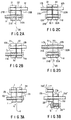
- Figs. 1 and 2A to 2D collectively show a method and apparatus for joining two tubes according to the technique of the present invention.
- Fig. 1 shows a tube joining apparatus 10.
- the tube joining apparatus 10 comprises a pair of tube holders, i.e., a rotatable holder 21 and a pressing holder 22, a cutter blade 30, a heating body 40, a cutter blade driving device 50, a tube holder rotating device 60, and a tube holder moving device 70.
- the cutter blade 30 is made of the metal such as copper, aluminum, or the alloy thereof.
- the heating body 40 is made of the electrical resistance type heating member such as stainless steel or Ni-Cr alloy, and the shape of the heating body 40 is wire type or film type.
- Each of the rotatable holder 21 and the pressing holder 22 consists of a split mold.
- the upper halves of the split molds are denoted by imaginary lines, with the lower mold halves being denoted by solid lines.
- Two parallel grooves 21, 21b are formed at the interface between the upper and lower mold halves of the rotatable holder 21.
- two parallel grooves 22a, 22b are formed at the interface between the upper and lower mold halves of the pressing holder 22.
- These grooves act as tube guiding holes 21A, 21B, 22A and 22B, respectively.
- the tube guiding hole 21A formed in the rotatable holder 21 is aligned with the tube guiding hole 22A formed in the pressing holder 22.
- the tube guiding hole 21B formed in the rotatable holder 21 is aligned with the tube guiding hole 22B formed in the pressing holder 22.
- the grooves 21a, 21b, 22a and 22b are formed shallower and wider in the interfacial region between the rotatable holder 21 and the pressing holder 22.
- One end of a rotary shaft 31 is connected to the tube holder rotating device, with the other end being connected to the rotatable holder 21.
- the tube guiding hole of the rotatable holder 21 which is originally aligned with one of the tube guiding holes of the pressing holder 22, is aligned with the other tube guiding hole of the pressing holder 22.
- the tube guiding hole 21A of the rotatable holder 21 is aligned with the tube guiding hole 22B of the pressing holder 22 after rotation of the rotatable holder by 180°.
- the tube guiding hole 21B is aligned with the tube guiding hole 22A.
- the pressing holder 22 is movable along a guide mechanism 24 toward and away from the rotatable holder 21.
- the reciprocating movement of the pressing holder 22 is performed by driving the tube holder moving device 70.
- the cutter blade 30 is preferably in the form of a thin disk (about 0.2 to 1.0 mm thickness) having cutting edges formed along the substantially circumferential periphery.
- a heating body 40 consisting of an electrical resistance type heating device is housed in the cutter blade 30 with the adhesive such as epory type or acryl type, with the result that the cut surfaces of the tubes are heated.
- the heating body 40 is preferably arranged in a radiate manner with the predetermined angle and distance.
- the cutter blade 30 is connected to a moving mechanism 31, which is further connected to the cutter blade driving device 50.
- the cutter blade 30 is reciprocated along the clearance between the rotatable holder 21 and the pressing holder 22, as denoted by broken lines in the drawing.
- the tube joining apparatus 10 of the construction described above is used for joining two tubes having substantially the same inner or outer diameter.
- a thermoplastic tube 11 which is connected to, for example, a first bag
- another tube 12 which is connected to a second bag
- these tubes 11 and 12 are inserted into and fixed within the tube guiding holes, as shown in Fig. 2A.
- the tube 11 is inserted through a hole including he tube guiding hole 21A formed in the rotatable holder 21 and the tube guiding hole 22A formed in the pressing holder 22, said tube guiding holes 21A and 22A communicating with each other.
- the tube 12 is inserted through a hole including the tube guiding holes 21B and 22B communicating with each other.
- the joining potions of the tubes 11 and 12 are pressurized by the rotatable holder 21 and the pressing holder 23 so as to be flattened.
- the cutter blade 30 is inserted through the clearance between the rotatable holder 21 and the pressing holder 22 by operating the cutter blade driving device 50 so as to cut the tubes 11 and 12, as shown in Fig. 2B.
- the cut end portions 11a, 12a of the tubes 11, 12 are separated from the main tube body portions 11b, 12b, respectively.
- the cutting edge surfaces of the cutter blade 30 are heated in advance by the heating body 40. It follows that the cut surfaces of the cut end portions 11a, 12a are somewhat melted, with the result that the mutually facing inner walls of these cut end portions are temperately sealed and, at the same time, tightly adhered to the cutting edge potions of the cutter blade 30.
- the cutting edge is heated up to the temperature enough to melt the tube and sterilize the tube.
- the rotatable holder 21 is rotated by 180°, with the cutter blade 30 held in the clearance between the rotatable holder 21 and the pressing holder 22 so as to keep the temporary sealing ensured.
- the main tube body portions 11b and 12b are aligned with each other, with the cut faces of these main tube body portions being positioned to face each other, as shown in Fig. 2C.
- the cut end portions 11a, 12a of the tubes are also aligned with each other such that the cut faces of these cut end portions are positioned to face each other.
- the cutter blade 30 is withdrawn form the clearance between the cut faces of the main tube body portions 11b, 12b and between the cut end portions 11a, 12a of the tubes, followed by immediately operating the tube holder driving device 70 so as to move the pressing holder 22 toward the rotatable holder 21 and, thus, to push the cut face of the main tube body portion 12b against the cut face of the main tube body portion 11b, as shown in Fig. 2D. Since the cut faces of the main tube body portions and the cut end potions of the tubes 11 and 12 are under molten state in this step, the main tube body portions 11b and 12b are welded to join each other. Likewise, the cut end portions 11a and 12a are welded to liquid-tightly join each other.
- the cut surfaces of the cut end portions 11a, 12a of the tubes are welded to join each other in the step of mutually fusing the cut surfaces of the tube body portions 11b, 12b. It follows that it is unnecessary to worry about the difficulty inherent in the prior art, i.e., the problem that the humor such as urine or blood, the peritoneal dialysis solution or the like remaining in the cut end portions comes outside or is scattered.
- the grooves 21a, 21b, 22a, and 22b in the rotatable holder 21 and the pressing holder 22 are formed shallower and wider in the interfacial region between the rotatable holder 21 and the pressing holder 22.
- the tubes inserted into these grooves are pressurized and collapsed when the upper mold halves of the rotatable holder and the pressing holder are engaged with the lower mold halves of these holders. In other words, the mutually facing regions of the inner surfaces of these tubes are brought into mutual contact so as to flatten these tubes.
- the present invention is not restricted to this embodiment.
- the grooves 21a, 21b, 22a, 22b may be circular in cross section such that the tubes inserted thereinto are substantially prevented from being collapsed.
- the rotatable holder 21 alone is rotated by 180°. Needless to say, however, it is also possible to rotate both the rotatable holder 21 and the pressing holder 22, provided that the relative rotation of 180° is achieved between these holders.
- the pressing holder 22 alone is moved toward the rotatable holder 21.
- the cutter blade 30 is in the form of a thin disk having cutting edges formed along the outer circumferential region.
- the cutter blade 30 it is of course possible for the cutter blade 30 to be of any optional shape.
- the cut surfaces of the cut end portions of the tubes are fused to each other during the step of welding the cut surfaces of the main tube body portions. It follows that it is unnecessary to worry about the difficulty inherent in the prior art, i.e., the difficulty that the humor such as urine or blood, the peritoneal dialysis solution or the like remaining in the cut end portions of the tubes comes outside or is scattered so as to stain or infect the working environment or the worker.
- the patient can be prevented from the infections caused by the vacteria, virus or the like.
Landscapes
- Engineering & Computer Science (AREA)
- Mechanical Engineering (AREA)
- Health & Medical Sciences (AREA)
- Heart & Thoracic Surgery (AREA)
- Hematology (AREA)
- General Health & Medical Sciences (AREA)
- Anesthesiology (AREA)
- Biomedical Technology (AREA)
- Toxicology (AREA)
- Life Sciences & Earth Sciences (AREA)
- Animal Behavior & Ethology (AREA)
- Pulmonology (AREA)
- Public Health (AREA)
- Veterinary Medicine (AREA)
- Physics & Mathematics (AREA)
- Thermal Sciences (AREA)
- External Artificial Organs (AREA)
- Lining Or Joining Of Plastics Or The Like (AREA)
Applications Claiming Priority (2)
| Application Number | Priority Date | Filing Date | Title |
|---|---|---|---|
| JP03099865A JP3096086B2 (ja) | 1991-04-05 | 1991-04-05 | チューブの接合方法及び装置 |
| JP99865/91 | 1991-04-05 |
Publications (2)
| Publication Number | Publication Date |
|---|---|
| EP0507321A1 true EP0507321A1 (de) | 1992-10-07 |
| EP0507321B1 EP0507321B1 (de) | 1995-06-28 |
Family
ID=14258702
Family Applications (1)
| Application Number | Title | Priority Date | Filing Date |
|---|---|---|---|
| EP92105781A Expired - Lifetime EP0507321B1 (de) | 1991-04-05 | 1992-04-03 | Verfahren und Vorrichtung zur Verbindung von Rohren |
Country Status (3)
| Country | Link |
|---|---|
| EP (1) | EP0507321B1 (de) |
| JP (1) | JP3096086B2 (de) |
| DE (1) | DE69203130T2 (de) |
Cited By (14)
| Publication number | Priority date | Publication date | Assignee | Title |
|---|---|---|---|---|
| EP0643975A1 (de) * | 1993-09-20 | 1995-03-22 | Terumo Kabushiki Kaisha | Beutelsystem zur Lagerung von Zellen und Methode zur Lagerung von Zellen nach diesem System |
| EP0778123A3 (de) * | 1995-12-08 | 1998-02-18 | Terumo Kabushiki Kaisha | Rohrverbindungsvorrichtung |
| EP0847847A1 (de) * | 1996-12-11 | 1998-06-17 | CKD Corporation | Rohrverbindungsvorrichtung |
| WO2004020179A1 (ja) * | 2002-08-30 | 2004-03-11 | Terumo Kabushiki Kaisha | チューブ接合装置及びチューブ接合方法 |
| WO2004022317A1 (ja) * | 2002-08-30 | 2004-03-18 | Terumo Kabushiki Kaisha | チューブ接合装置及びチューブ接合方法 |
| WO2009006495A2 (en) | 2007-07-05 | 2009-01-08 | Baxter International Inc. | Peritoneal dialysis patient connection system |
| CH698798B1 (de) * | 2006-09-20 | 2009-10-30 | Wave Biotech Ag | Verfahren und Vorrichtung zum Verbinden zweier Leitungen aus thermoplastischem Kunststoff durch Verschweissen. |
| WO2010118546A1 (de) | 2009-04-14 | 2010-10-21 | Reed Electronics Ag | Vorrichtung zum verschweissen von thermoplastischen schläuchen |
| CN103767741A (zh) * | 2013-12-19 | 2014-05-07 | 武汉佰美斯医疗科技有限公司 | 血袋无菌接驳方法及该方法使用的设备 |
| WO2014189446A1 (en) | 2013-05-20 | 2014-11-27 | Ge Healthcare Bio-Sciences Ab | Apparatus and method for making a sterile connection of flexible tubing |
| EP3126118A1 (de) * | 2014-04-02 | 2017-02-08 | GE Healthcare Bio-Sciences AB | Fixierer -und versieglerintegriertes system |
| US20170276281A1 (en) * | 2010-08-18 | 2017-09-28 | Fresenius Kabi Deutschland Gmbh | Method and device for the sterile connection of pipes |
| US10307582B2 (en) | 2011-12-21 | 2019-06-04 | Fenwal, Inc. | Fluid flow conduits and apparatus and methods for making and joining fluid conduits |
| WO2023281258A1 (en) * | 2021-07-06 | 2023-01-12 | Cellularorigins Limited | Automated apparatus |
Families Citing this family (15)
| Publication number | Priority date | Publication date | Assignee | Title |
|---|---|---|---|---|
| JPH07253451A (ja) * | 1994-03-15 | 1995-10-03 | Nec Corp | 回路検査用延長接続治具 |
| JP4262249B2 (ja) * | 2003-06-26 | 2009-05-13 | テルモ株式会社 | チューブ接合装置 |
| JP4073371B2 (ja) | 2003-06-30 | 2008-04-09 | テルモ株式会社 | チューブクランプ装置及びチューブ接合装置 |
| JP4046655B2 (ja) | 2003-07-04 | 2008-02-13 | テルモ株式会社 | チューブ接合装置 |
| JP4821966B2 (ja) * | 2005-08-24 | 2011-11-24 | 株式会社ジェイ・エム・エス | 医療用コネクタの手動式脱着装置 |
| JP4821968B2 (ja) * | 2005-09-14 | 2011-11-24 | 株式会社ジェイ・エム・エス | 医療用コネクタの手動式脱着装置 |
| JP4711062B2 (ja) * | 2005-09-21 | 2011-06-29 | 株式会社ジェイ・エム・エス | 医療用コネクタの手動式脱着装置 |
| US8448992B2 (en) | 2011-02-16 | 2013-05-28 | Fenwal, Inc. | Sterile docking device, medical fluid flow system with sterile docking device and method of using same |
| US9308709B2 (en) | 2013-06-06 | 2016-04-12 | Fenwal, Inc. | Bonding apparatus and method |
| US9440396B2 (en) | 2014-06-19 | 2016-09-13 | Fenwal, Inc. | Sterile connection device for making multiple connections |
| US9533135B2 (en) | 2014-06-19 | 2017-01-03 | Fenwal, Inc. | Method for forming, opening and/or evaluating a connection site |
| US9839582B2 (en) | 2014-12-02 | 2017-12-12 | Fenwal, Inc. | Sterile connection syringe assemblies |
| CN105459392B (zh) * | 2015-12-31 | 2018-08-07 | 中国科学院苏州生物医学工程技术研究所 | 一种管连接装置 |
| US10919235B2 (en) | 2017-06-07 | 2021-02-16 | Fenwal, Inc. | Apparatus and method for mechanically opening a connection site |
| WO2023233532A1 (ja) * | 2022-05-31 | 2023-12-07 | 株式会社サンプラテック | チューブ接続システム、およびチューブコネクタセット |
Citations (3)
| Publication number | Priority date | Publication date | Assignee | Title |
|---|---|---|---|---|
| EP0194873A2 (de) * | 1985-03-12 | 1986-09-17 | E.I. Du Pont De Nemours And Company | Verfahren und Gerät zum kalten Schneiden und zum sterilen Verbinden |
| FR2578782A1 (fr) * | 1985-03-15 | 1986-09-19 | Sifc | Appareil de liaison de deux extremites de tubes thermoplastiques |
| EP0238750A1 (de) * | 1985-11-27 | 1987-09-30 | BAXTER INTERNATIONAL INC. (a Delaware corporation) | Kupplungseinrichtung, insbesondere für Peritonealdialyse |
-
1991
- 1991-04-05 JP JP03099865A patent/JP3096086B2/ja not_active Expired - Fee Related
-
1992
- 1992-04-03 EP EP92105781A patent/EP0507321B1/de not_active Expired - Lifetime
- 1992-04-03 DE DE69203130T patent/DE69203130T2/de not_active Expired - Fee Related
Patent Citations (3)
| Publication number | Priority date | Publication date | Assignee | Title |
|---|---|---|---|---|
| EP0194873A2 (de) * | 1985-03-12 | 1986-09-17 | E.I. Du Pont De Nemours And Company | Verfahren und Gerät zum kalten Schneiden und zum sterilen Verbinden |
| FR2578782A1 (fr) * | 1985-03-15 | 1986-09-19 | Sifc | Appareil de liaison de deux extremites de tubes thermoplastiques |
| EP0238750A1 (de) * | 1985-11-27 | 1987-09-30 | BAXTER INTERNATIONAL INC. (a Delaware corporation) | Kupplungseinrichtung, insbesondere für Peritonealdialyse |
Cited By (39)
| Publication number | Priority date | Publication date | Assignee | Title |
|---|---|---|---|---|
| EP0643975A1 (de) * | 1993-09-20 | 1995-03-22 | Terumo Kabushiki Kaisha | Beutelsystem zur Lagerung von Zellen und Methode zur Lagerung von Zellen nach diesem System |
| US6068970A (en) * | 1993-09-20 | 2000-05-30 | Terumo Kabushiki Kaisha | Method of preserving cells using cell storage bag system |
| EP0778123A3 (de) * | 1995-12-08 | 1998-02-18 | Terumo Kabushiki Kaisha | Rohrverbindungsvorrichtung |
| US5802689A (en) * | 1995-12-08 | 1998-09-08 | Terumo Kabushiki Kaisha | Tube connecting apparatus |
| EP0847847A1 (de) * | 1996-12-11 | 1998-06-17 | CKD Corporation | Rohrverbindungsvorrichtung |
| EP0953431A2 (de) * | 1996-12-11 | 1999-11-03 | CKD Corporation | Rohrverbindungsvorrichtung |
| US6026882A (en) * | 1996-12-11 | 2000-02-22 | Ckd Corporation | Tube connecting apparatus |
| EP0953431A3 (de) * | 1996-12-11 | 2001-08-01 | Terumo Kabushiki Kaisha | Rohrverbindungsvorrichtung |
| US6341637B1 (en) | 1996-12-11 | 2002-01-29 | Terumo Kabushiki Kaisha | Tube connecting apparatus |
| CN1668449B (zh) * | 2002-08-30 | 2010-05-05 | 泰尔茂株式会社 | 管接合装置及管接合方法 |
| WO2004020179A1 (ja) * | 2002-08-30 | 2004-03-11 | Terumo Kabushiki Kaisha | チューブ接合装置及びチューブ接合方法 |
| US7371305B2 (en) | 2002-08-30 | 2008-05-13 | Terumo Kabushiki Kaisha | Tube connecting apparatus and tube connecting method |
| AU2003261827B2 (en) * | 2002-08-30 | 2008-09-11 | Terumo Kabushiki Kaisha | Tube-joining apparatus and tube-joining method |
| WO2004022317A1 (ja) * | 2002-08-30 | 2004-03-18 | Terumo Kabushiki Kaisha | チューブ接合装置及びチューブ接合方法 |
| AU2003261828B2 (en) * | 2002-08-30 | 2009-01-29 | Terumo Kabushiki Kaisha | Tube-joining apparatus and tube-joining method |
| US7657996B2 (en) | 2002-08-30 | 2010-02-09 | Terumo Kabushiki Kaisha | Tube connecting apparatus and tube connecting method |
| CH698798B1 (de) * | 2006-09-20 | 2009-10-30 | Wave Biotech Ag | Verfahren und Vorrichtung zum Verbinden zweier Leitungen aus thermoplastischem Kunststoff durch Verschweissen. |
| WO2009006495A3 (en) * | 2007-07-05 | 2009-03-12 | Baxter Int | Peritoneal dialysis patient connection system |
| WO2009006495A2 (en) | 2007-07-05 | 2009-01-08 | Baxter International Inc. | Peritoneal dialysis patient connection system |
| WO2010118546A1 (de) | 2009-04-14 | 2010-10-21 | Reed Electronics Ag | Vorrichtung zum verschweissen von thermoplastischen schläuchen |
| US8857485B2 (en) | 2009-04-14 | 2014-10-14 | Reed Electronics Ag | Apparatus for welding together thermoplastic hoses |
| US20170276281A1 (en) * | 2010-08-18 | 2017-09-28 | Fresenius Kabi Deutschland Gmbh | Method and device for the sterile connection of pipes |
| US11351742B2 (en) | 2010-08-18 | 2022-06-07 | Fresenius Kabi Deutschland Gmbh | Method and device for the sterile connection of pipes |
| US10569478B2 (en) | 2010-08-18 | 2020-02-25 | Fresenius Kabi Deutschland Gmbh | Method and device for the sterile connection of pipes |
| US10549484B2 (en) | 2010-08-18 | 2020-02-04 | Fresenius Kabi Deutschland Gmbh | Method and device for the sterile connection of pipes |
| US10307582B2 (en) | 2011-12-21 | 2019-06-04 | Fenwal, Inc. | Fluid flow conduits and apparatus and methods for making and joining fluid conduits |
| CN105209107A (zh) * | 2013-05-20 | 2015-12-30 | 通用电气健康护理生物科学股份公司 | 用于进行柔性管材的消毒连接的装置和方法 |
| US10195416B2 (en) | 2013-05-20 | 2019-02-05 | Ge Healthcare Bio-Sciences Ab | Apparatus and method for making a sterile connection of flexible tubing |
| CN105209107B (zh) * | 2013-05-20 | 2019-03-12 | 通用电气健康护理生物科学股份公司 | 用于进行柔性管材的消毒连接的装置和方法 |
| WO2014189446A1 (en) | 2013-05-20 | 2014-11-27 | Ge Healthcare Bio-Sciences Ab | Apparatus and method for making a sterile connection of flexible tubing |
| US10029088B2 (en) | 2013-12-19 | 2018-07-24 | Wuhan Bms Medicaltech Co., Ltd | Blood bag sterile connection method and device used in the method |
| CN103767741B (zh) * | 2013-12-19 | 2015-08-19 | 武汉佰美斯医疗科技有限公司 | 血袋无菌接驳方法及该方法使用的设备 |
| CN103767741A (zh) * | 2013-12-19 | 2014-05-07 | 武汉佰美斯医疗科技有限公司 | 血袋无菌接驳方法及该方法使用的设备 |
| EP3126118A4 (de) * | 2014-04-02 | 2017-03-29 | GE Healthcare Bio-Sciences AB | Fixierer -und versieglerintegriertes system |
| CN106457674A (zh) * | 2014-04-02 | 2017-02-22 | 通用电气健康护理生物科学股份公司 | 合并器和密封器集成系统 |
| US10081135B2 (en) | 2014-04-02 | 2018-09-25 | Ge Healthcare Bio-Sciences Ab | Fuser and sealer integrated system |
| EP3126118A1 (de) * | 2014-04-02 | 2017-02-08 | GE Healthcare Bio-Sciences AB | Fixierer -und versieglerintegriertes system |
| CN106457674B (zh) * | 2014-04-02 | 2019-12-10 | 通用电气健康护理生物科学股份公司 | 合并器和密封器集成系统 |
| WO2023281258A1 (en) * | 2021-07-06 | 2023-01-12 | Cellularorigins Limited | Automated apparatus |
Also Published As
| Publication number | Publication date |
|---|---|
| EP0507321B1 (de) | 1995-06-28 |
| DE69203130T2 (de) | 1995-11-02 |
| JPH04308731A (ja) | 1992-10-30 |
| DE69203130D1 (de) | 1995-08-03 |
| JP3096086B2 (ja) | 2000-10-10 |
Similar Documents
| Publication | Publication Date | Title |
|---|---|---|
| EP0507321B1 (de) | Verfahren und Vorrichtung zur Verbindung von Rohren | |
| US4737214A (en) | Method for providing sterile connection of plastic tubes or the like | |
| US4897138A (en) | Sealing of plastic tubes | |
| EP1740366B1 (de) | Verfahren zur sterilen verbindung von schläuchen | |
| US4507119A (en) | Sterile docking process, apparatus and system | |
| US4443215A (en) | Sterile docking process, apparatus and system | |
| EP2038000B1 (de) | Verfahren zum Verbinden thermoplastischer Schläuche | |
| CA1075649A (en) | Aseptic fluid transfer system | |
| EP0508373B1 (de) | Steriles Schweissen von Kunststoffschläuchen | |
| EP0508474A2 (de) | Steriles Schweissen von Kunststoffschläuchen | |
| JPH08427B2 (ja) | 断熱手段、チューブを密封する方法および装置 | |
| KR20050033554A (ko) | 튜브 접합 장치 및 튜브 접합 방법 | |
| CA2043456A1 (en) | Sterile entry/exit total containment process for closed systems using plastic tubes | |
| EP0903214B1 (de) | Vorrichtung zum sterilen Verschweissen von Kunststoffrohren unter hermetischem Abschluss | |
| US20150367569A1 (en) | Sterile connection device for making multiple connections | |
| EP0515811A2 (de) | Steriles Schweissen von Kunststoffschläuchen | |
| EP0723851A2 (de) | Gerät zum hermetischen Verbinden/Abschliessen | |
| JP2710038B2 (ja) | チューブの無菌接続方法及び装置 | |
| EP0852180B1 (de) | Medizinische Vorrichtung mit Verzweigung und Verfahren zu ihrer Herstellung | |
| JPS6130582B2 (de) | ||
| JPS61290035A (ja) | 無菌接続用構造物およびその接続方法 | |
| GB1564465A (en) | Tube coupling | |
| JPH06197957A (ja) | 無菌切離し方法 | |
| JPH07124249A (ja) | 体液処理用回路及びその製造方法 | |
| JP2002011792A (ja) | 熱可塑性樹脂管の分岐接合方法およびその接合方法に用いる分岐管 |
Legal Events
| Date | Code | Title | Description |
|---|---|---|---|
| PUAI | Public reference made under article 153(3) epc to a published international application that has entered the european phase |
Free format text: ORIGINAL CODE: 0009012 |
|
| 17P | Request for examination filed |
Effective date: 19920403 |
|
| AK | Designated contracting states |
Kind code of ref document: A1 Designated state(s): BE DE FR GB IT NL SE |
|
| 17Q | First examination report despatched |
Effective date: 19940713 |
|
| GRAA | (expected) grant |
Free format text: ORIGINAL CODE: 0009210 |
|
| ITF | It: translation for a ep patent filed |
Owner name: FUMERO BREVETTI S.N.C. |
|
| AK | Designated contracting states |
Kind code of ref document: B1 Designated state(s): BE DE FR GB IT NL SE |
|
| PG25 | Lapsed in a contracting state [announced via postgrant information from national office to epo] |
Ref country code: NL Free format text: LAPSE BECAUSE OF FAILURE TO SUBMIT A TRANSLATION OF THE DESCRIPTION OR TO PAY THE FEE WITHIN THE PRESCRIBED TIME-LIMIT Effective date: 19950628 Ref country code: BE Effective date: 19950628 |
|
| ET | Fr: translation filed | ||
| REF | Corresponds to: |
Ref document number: 69203130 Country of ref document: DE Date of ref document: 19950803 |
|
| PG25 | Lapsed in a contracting state [announced via postgrant information from national office to epo] |
Ref country code: SE Effective date: 19950928 |
|
| NLV1 | Nl: lapsed or annulled due to failure to fulfill the requirements of art. 29p and 29m of the patents act | ||
| PG25 | Lapsed in a contracting state [announced via postgrant information from national office to epo] |
Ref country code: GB Effective date: 19960403 |
|
| PLBE | No opposition filed within time limit |
Free format text: ORIGINAL CODE: 0009261 |
|
| STAA | Information on the status of an ep patent application or granted ep patent |
Free format text: STATUS: NO OPPOSITION FILED WITHIN TIME LIMIT |
|
| 26N | No opposition filed | ||
| GBPC | Gb: european patent ceased through non-payment of renewal fee |
Effective date: 19960403 |
|
| PGFP | Annual fee paid to national office [announced via postgrant information from national office to epo] |
Ref country code: IT Payment date: 20090421 Year of fee payment: 18 Ref country code: FR Payment date: 20090417 Year of fee payment: 18 Ref country code: DE Payment date: 20090327 Year of fee payment: 18 |
|
| REG | Reference to a national code |
Ref country code: FR Ref legal event code: ST Effective date: 20101230 |
|
| PG25 | Lapsed in a contracting state [announced via postgrant information from national office to epo] |
Ref country code: DE Free format text: LAPSE BECAUSE OF NON-PAYMENT OF DUE FEES Effective date: 20101103 |
|
| PG25 | Lapsed in a contracting state [announced via postgrant information from national office to epo] |
Ref country code: IT Free format text: LAPSE BECAUSE OF NON-PAYMENT OF DUE FEES Effective date: 20100403 |
|
| PG25 | Lapsed in a contracting state [announced via postgrant information from national office to epo] |
Ref country code: FR Free format text: LAPSE BECAUSE OF NON-PAYMENT OF DUE FEES Effective date: 20100430 |