EP0507201A2 - Procédé de contrôle du nombre de tours moteur - Google Patents
Procédé de contrôle du nombre de tours moteur Download PDFInfo
- Publication number
- EP0507201A2 EP0507201A2 EP92105096A EP92105096A EP0507201A2 EP 0507201 A2 EP0507201 A2 EP 0507201A2 EP 92105096 A EP92105096 A EP 92105096A EP 92105096 A EP92105096 A EP 92105096A EP 0507201 A2 EP0507201 A2 EP 0507201A2
- Authority
- EP
- European Patent Office
- Prior art keywords
- force
- spring
- control
- power source
- speed
- Prior art date
- Legal status (The legal status is an assumption and is not a legal conclusion. Google has not performed a legal analysis and makes no representation as to the accuracy of the status listed.)
- Withdrawn
Links
Images


Classifications
-
- F—MECHANICAL ENGINEERING; LIGHTING; HEATING; WEAPONS; BLASTING
- F02—COMBUSTION ENGINES; HOT-GAS OR COMBUSTION-PRODUCT ENGINE PLANTS
- F02D—CONTROLLING COMBUSTION ENGINES
- F02D1/00—Controlling fuel-injection pumps, e.g. of high pressure injection type
- F02D1/02—Controlling fuel-injection pumps, e.g. of high pressure injection type not restricted to adjustment of injection timing, e.g. varying amount of fuel delivered
- F02D1/04—Controlling fuel-injection pumps, e.g. of high pressure injection type not restricted to adjustment of injection timing, e.g. varying amount of fuel delivered by mechanical means dependent on engine speed, e.g. using centrifugal governors
-
- F—MECHANICAL ENGINEERING; LIGHTING; HEATING; WEAPONS; BLASTING
- F02—COMBUSTION ENGINES; HOT-GAS OR COMBUSTION-PRODUCT ENGINE PLANTS
- F02D—CONTROLLING COMBUSTION ENGINES
- F02D1/00—Controlling fuel-injection pumps, e.g. of high pressure injection type
- F02D1/02—Controlling fuel-injection pumps, e.g. of high pressure injection type not restricted to adjustment of injection timing, e.g. varying amount of fuel delivered
- F02D1/08—Transmission of control impulse to pump control, e.g. with power drive or power assistance
- F02D1/10—Transmission of control impulse to pump control, e.g. with power drive or power assistance mechanical
-
- G—PHYSICS
- G05—CONTROLLING; REGULATING
- G05B—CONTROL OR REGULATING SYSTEMS IN GENERAL; FUNCTIONAL ELEMENTS OF SUCH SYSTEMS; MONITORING OR TESTING ARRANGEMENTS FOR SUCH SYSTEMS OR ELEMENTS
- G05B11/00—Automatic controllers
- G05B11/01—Automatic controllers electric
- G05B11/36—Automatic controllers electric with provision for obtaining particular characteristics, e.g. proportional, integral, differential
-
- G—PHYSICS
- G05—CONTROLLING; REGULATING
- G05D—SYSTEMS FOR CONTROLLING OR REGULATING NON-ELECTRIC VARIABLES
- G05D13/00—Control of linear speed; Control of angular speed; Control of acceleration or deceleration, e.g. of a prime mover
- G05D13/34—Control of linear speed; Control of angular speed; Control of acceleration or deceleration, e.g. of a prime mover with auxiliary non-electric power
Definitions
- the invention is based on a method according to the preamble of the main claim.
- the aim of the invention is to provide a method by means of which a speed control with any P-degree, which can also be small or even negative, can be carried out. Nevertheless, a stable speed behavior should be achieved. This could, for example, operate electricity generators or water pumps with a much higher control quality.
- the control which speaks of an overall control range, relates to the control after the start phase and is often referred to in the literature as final speed control (for example Bosch, technical instruction, diesel injection equipment, speed controller for in-line injection pumps, Stuttgart 1975, Robert Bosch GmbH) designated.
- final speed control for example Bosch, technical instruction, diesel injection equipment, speed controller for in-line injection pumps, Stuttgart 1975, Robert Bosch GmbH
- the regulation takes place practically in stages, the dimensions of which can be determined by the size of the resistors.
- a continuous control takes place at each stage, which can be kept very stable due to a large positive P-degree.
- a centrifugal force controller is provided, the centrifugal weights of which are opposed to a force in the usual way.
- this force is generated by three different sources.
- One of these sources has two possible levels of force.
- This "bistable" power source is switched by the force emanating from the centrifugal weights. It can act against the centrifugal weights when reducing the injection quantity and against one of the other power sources when increasing.
- the force opposite to the centrifugal weights is only generated by two force sources.
- One of these power sources only works in the idle range, while the other works constantly.
- This constantly acting force increases when the control rod is moved in the throttle direction only in the load area more than the force emanating from the centrifugal weights.
- the force emanating from the centrifugal weights increases more.
- This results in two stable control phases, namely a control phase in the load range at high speed and a control phase in the idling range at low speed. This can have a particularly advantageous effect, for example in the case of compressors in which only two operating states occur.
- the controller switches to idle or full load speed.
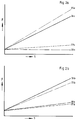
- 1a shows the characteristic curve for a controller according to the invention with a small but positive P-degree.
- the control range extends over a control rod path RW from 0 to 100, with 100 corresponding to the control rod path at full load. If the engine is running at approximately full load, the speed in the area of the control phase 22a is controlled according to the load and thus the control rod travel. If the load changes only in the area 40, the speed on line 22a is readjusted. However, if the load falls below the range 40, a jump takes place. No regulation takes place in this area 24a; the height of the jump depends on the change in load.
- control is carried out, for example, in the control phase 22a, which in FIG. 1 is below the top control phase.
- the jump can also extend to one of the next control phases.
- the load increases by an amount greater than that due to the control phase 22a is the amount covered, a jump 41 takes place upwards.
- this control behavior does not only take place in the full-load range, but extends to the entire control range.
- FIG. 1 shows that control ranges 22a given by way of example and the associated jump phases.
- the jump phases 24a also still have a positive P-degree, which also results in a positive mean overall P-degree 21a.
- Fig. 1b corresponding drawing elements are provided with the same number and the addition b.
- the jump phases 24b here have a strongly negative P degree, so that there is also a negative mean overall P degree 21b.
- FIG. 2 shows the different characteristic curves of the resistors, as are used in the exemplary embodiment according to FIG. 3.
- a positive mean overall P-degree is assumed, in Fig. 2b a negative mean overall P-degree.
- the line 25 a, b shows the force curve on the spring 11, measured over the path of the articulation point of the spring 11 on the control lever 9, which this describes during the control process.
- Line 26 a, b shows the force curve which the centrifugal weights 41 exert when moving around the articulation points 42.
- the force curve is related to constant speed.
- the line 27 a, b represents the force profile that the spring 14 exerts on the control lever a.
- Line 28 denotes the force measured by the pin 18 over the control rod travel acts on the friction surface 16.
- a shaft 3 connected to the motor via the gearwheel 4 is mounted in a frame 1, 2.
- a centrifugal weight carrier 7 is connected in a rotationally fixed manner to the shaft, with which centrifugal weight 43 is pivotably connected via the joint 42.
- the position of the flyweight 41 is transmitted to the control lever 9 via a sliding sleeve 8. This is pivoted at point 10.
- the fulcrum 10 of the control lever is located between the articulation point of the spring 11 and the point of application of the sliding sleeve 8.
- the control lever 9 With its longer arm, the control lever 9 is connected to the delivery rate control rod 5 via the driving pin 12 and an elongated hole.
- the delivery control rod 5 can consequently be displaced parallel to the shaft 3 by pivoting the lever 9 about the point 10.
- the regulator lever 9 is provided on its longer arm with a driver 19 which interacts with a functional part 13 which is firmly connected to a sliding rod 6.
- the functional part 13 has a fixed abutment surface 20 and receives the pin 15 on the opposite side, which is supported on the functional part 13 via the spring 14. This can be done for adjustment purposes
- Functional part 13 may be provided with a clamping screw 44 with which it can be fixed on the rod 6.
- the bearing frame 2 also serves as a receptacle for the friction pin 18, which is supported on the frame 2 via the spring 17 and presses on the sliding surface 16 of the rod 6.
- the control rod 5 shifts in a direction which throttles the injection quantity. In the event of small changes in load, this results in a balance of forces, so that the engine speed remains practically constant. However, if the load drop is very large, the control lever 9 is pivoted to a large extent. The driver 19 presses the spring 14 completely together and now acts directly against the functional part 13. In this state, the force with which the driver 19 acts against the functional part 13 can increase by a certain amount without resulting in a further Movement of the regulator rod 5 and thus throttling the injection quantity results.
- the exemplary embodiment according to FIG. 4 shows an arrangement which would be favorable in the case of limited space when installing in distributor injection pumps.
- the control lever 9 is again pivoted about the pivot pin 10.
- the functional part 13a which contains the stop surface 20, the pin 15 and the spring 14, is firmly connected to the control lever 9.
- the pin 15 presses on a further pivot lever 29, which is also rotatably mounted about the axis 10.
- this lever 29 is not freely rotatable, but is braked by the friction pin 18, which is pressed onto the axis 10 by the spring 17.
- FIG. 5 describes an embodiment that can be used, for example, to control a compressor motor.
- the spring 11c is attached to the bearing frame 2 here in such a way that the increase in force with the progressive movement of the control lever 9 in the counterclockwise direction becomes less and less.
Landscapes
- Engineering & Computer Science (AREA)
- Physics & Mathematics (AREA)
- General Physics & Mathematics (AREA)
- Automation & Control Theory (AREA)
- Chemical & Material Sciences (AREA)
- Combustion & Propulsion (AREA)
- Mechanical Engineering (AREA)
- General Engineering & Computer Science (AREA)
- Power Engineering (AREA)
- High-Pressure Fuel Injection Pump Control (AREA)
Applications Claiming Priority (2)
| Application Number | Priority Date | Filing Date | Title |
|---|---|---|---|
| DE19914110493 DE4110493C2 (de) | 1991-03-30 | 1991-03-30 | Verfahren und Vorrichtung zum Regeln der Drehzahl von Kraftmaschinen |
| DE4110493 | 1991-03-30 |
Publications (2)
| Publication Number | Publication Date |
|---|---|
| EP0507201A2 true EP0507201A2 (fr) | 1992-10-07 |
| EP0507201A3 EP0507201A3 (en) | 1993-03-17 |
Family
ID=6428562
Family Applications (1)
| Application Number | Title | Priority Date | Filing Date |
|---|---|---|---|
| EP19920105096 Withdrawn EP0507201A3 (en) | 1991-03-30 | 1992-03-25 | Method for controlling the speed of rotations of engines |
Country Status (2)
| Country | Link |
|---|---|
| EP (1) | EP0507201A3 (fr) |
| DE (1) | DE4110493C2 (fr) |
Citations (7)
| Publication number | Priority date | Publication date | Assignee | Title |
|---|---|---|---|---|
| DE3018720A1 (de) * | 1980-05-16 | 1981-11-26 | Daimler-Benz Ag, 7000 Stuttgart | Regler fuer einspritzpumpen an brennkraftmaschinen |
| US4305363A (en) * | 1978-10-11 | 1981-12-15 | Diesel Kiki Co., Ltd. | Centrifugal governor |
| GB2110420A (en) * | 1981-12-02 | 1983-06-15 | Bosch Gmbh Robert | Adjusting device for a fuel delivery quantity adjusting member of a fuel injection pump |
| DE3242876A1 (de) * | 1981-12-30 | 1983-07-14 | Friedmann & Maier AG, 5400 Hallein, Salzburg | Regler fuer die mengenregelung von einspritzpumpen einer einspritzbrennkraftmaschine |
| DE3445894A1 (de) * | 1983-12-23 | 1985-07-04 | Piaggio & C. S.p.A., Genua/Genova | Kraftstoffzufuhrregler eines dieselmotors in der anlassstufe |
| EP0158846A2 (fr) * | 1984-04-19 | 1985-10-23 | Robert Bosch Gmbh | Régulateur centrifuge pour moteurs à combustion interne à injection de combustible |
| WO1988002810A1 (fr) * | 1986-10-20 | 1988-04-21 | Elsbett L | Agencement de regulation pour systeme d'injection de carburant de moteur a combustion interne |
Family Cites Families (3)
| Publication number | Priority date | Publication date | Assignee | Title |
|---|---|---|---|---|
| JPS4916128B1 (fr) * | 1970-09-28 | 1974-04-19 | ||
| DD212165A3 (de) * | 1982-12-27 | 1984-08-01 | Dresden Kraftfahrzeug Veb | Fliehkraftdrehzahlregler mit angleichung fuer kraftstoffeinspritzpumpen |
| DE4001789C1 (fr) * | 1990-01-23 | 1991-03-14 | Mercedes-Benz Aktiengesellschaft, 7000 Stuttgart, De |
-
1991
- 1991-03-30 DE DE19914110493 patent/DE4110493C2/de not_active Expired - Fee Related
-
1992
- 1992-03-25 EP EP19920105096 patent/EP0507201A3/de not_active Withdrawn
Patent Citations (7)
| Publication number | Priority date | Publication date | Assignee | Title |
|---|---|---|---|---|
| US4305363A (en) * | 1978-10-11 | 1981-12-15 | Diesel Kiki Co., Ltd. | Centrifugal governor |
| DE3018720A1 (de) * | 1980-05-16 | 1981-11-26 | Daimler-Benz Ag, 7000 Stuttgart | Regler fuer einspritzpumpen an brennkraftmaschinen |
| GB2110420A (en) * | 1981-12-02 | 1983-06-15 | Bosch Gmbh Robert | Adjusting device for a fuel delivery quantity adjusting member of a fuel injection pump |
| DE3242876A1 (de) * | 1981-12-30 | 1983-07-14 | Friedmann & Maier AG, 5400 Hallein, Salzburg | Regler fuer die mengenregelung von einspritzpumpen einer einspritzbrennkraftmaschine |
| DE3445894A1 (de) * | 1983-12-23 | 1985-07-04 | Piaggio & C. S.p.A., Genua/Genova | Kraftstoffzufuhrregler eines dieselmotors in der anlassstufe |
| EP0158846A2 (fr) * | 1984-04-19 | 1985-10-23 | Robert Bosch Gmbh | Régulateur centrifuge pour moteurs à combustion interne à injection de combustible |
| WO1988002810A1 (fr) * | 1986-10-20 | 1988-04-21 | Elsbett L | Agencement de regulation pour systeme d'injection de carburant de moteur a combustion interne |
Also Published As
| Publication number | Publication date |
|---|---|
| DE4110493A1 (de) | 1992-10-01 |
| EP0507201A3 (en) | 1993-03-17 |
| DE4110493C2 (de) | 1994-08-04 |
Similar Documents
| Publication | Publication Date | Title |
|---|---|---|
| DE2224755C3 (de) | Fliehkraftdrehzahlregler für Einspritzbrennkraftmaschinen | |
| DE2526148C2 (de) | Regeleinrichtung für die Kraftstoffzufuhr von Einspritzbrennkraftmaschinen | |
| DE2656261C2 (de) | Fliehkraftdrehzahlregler für Einspritzbrennkraftmaschinen | |
| DE2224758C3 (de) | Fliehkraftdrehzahlregler für Einspritzbrennkraftmaschinen | |
| DE3144173C2 (de) | Drehzahlregler für Einspritzbrennkraftmaschinen | |
| DE4129837C2 (de) | Drehzahlregler für Kraftstoffeinspritzpumpen von Brennkraftmaschinen | |
| DE4110493C2 (de) | Verfahren und Vorrichtung zum Regeln der Drehzahl von Kraftmaschinen | |
| DE2855889A1 (de) | Fliehkraftdrehzahlregler fuer einspritzbrennkraftmaschinen, insbesondere leerlauf-enddrehzahlregler fuer fahrzeugdieselmotoren | |
| DE2224756C3 (de) | Fliehkraftdrehzahlregler für Einspritzbrennkraftmaschinen | |
| DE3805691A1 (de) | Mechanischer drehzahlregler fuer eine brennkraftmaschine mit einer einstellbaren angleichvorrichtung | |
| EP0320617A2 (fr) | Régulateur pour pompes à injection de combustible | |
| DE814814C (de) | Fliehkraftregler fuer Brennkraftmaschinen | |
| DE2224757A1 (de) | Kliehkraftdrehzahlregler fuer einspritzbrennkraftmaschinen | |
| EP0158846A2 (fr) | Régulateur centrifuge pour moteurs à combustion interne à injection de combustible | |
| DE2802934A1 (de) | Fliehkraftdrehzahlregler fuer brennkraftmaschinen | |
| EP0436054B1 (fr) | Régulateur de vitesse pour une pompe à injection de combustible pour moteurs à combustion interne | |
| DE3050563C2 (fr) | ||
| DE2631381C2 (fr) | ||
| WO2005052342A2 (fr) | Regulateur de vitesse pour moteurs a combustion interne stationnaires | |
| DE3435986A1 (de) | Drehzahlregler fuer kraftstoffeinspritzpumpen | |
| DE1954834C3 (de) | Fliehkraftdrehzahlregler für Einspritzbrennkraftmaschinen | |
| DE3703628A1 (de) | Fliehkraftdrehzahlregler fuer einspritzpumpen | |
| DE4115301A1 (de) | Steuerkapsel fuer einen fliehkraftdrehzahlregler | |
| DE3242876A1 (de) | Regler fuer die mengenregelung von einspritzpumpen einer einspritzbrennkraftmaschine | |
| DE4201151A1 (de) | Verfahren und vorrichtung zur steuerung |
Legal Events
| Date | Code | Title | Description |
|---|---|---|---|
| PUAI | Public reference made under article 153(3) epc to a published international application that has entered the european phase |
Free format text: ORIGINAL CODE: 0009012 |
|
| AK | Designated contracting states |
Kind code of ref document: A2 Designated state(s): FR GB IT |
|
| PUAL | Search report despatched |
Free format text: ORIGINAL CODE: 0009013 |
|
| AK | Designated contracting states |
Kind code of ref document: A3 Designated state(s): FR GB IT |
|
| STAA | Information on the status of an ep patent application or granted ep patent |
Free format text: STATUS: THE APPLICATION IS DEEMED TO BE WITHDRAWN |
|
| 18D | Application deemed to be withdrawn |
Effective date: 19930918 |