EP0504635B1 - Water/air radiator for watercooled internal combustion engine - Google Patents
Water/air radiator for watercooled internal combustion engine Download PDFInfo
- Publication number
- EP0504635B1 EP0504635B1 EP92103308A EP92103308A EP0504635B1 EP 0504635 B1 EP0504635 B1 EP 0504635B1 EP 92103308 A EP92103308 A EP 92103308A EP 92103308 A EP92103308 A EP 92103308A EP 0504635 B1 EP0504635 B1 EP 0504635B1
- Authority
- EP
- European Patent Office
- Prior art keywords
- water
- air radiator
- free end
- radiator according
- water tank
- Prior art date
- Legal status (The legal status is an assumption and is not a legal conclusion. Google has not performed a legal analysis and makes no representation as to the accuracy of the status listed.)
- Expired - Lifetime
Links
- XLYOFNOQVPJJNP-UHFFFAOYSA-N water Substances O XLYOFNOQVPJJNP-UHFFFAOYSA-N 0.000 title claims description 81
- 238000002485 combustion reaction Methods 0.000 title claims description 3
- 229920003023 plastic Polymers 0.000 claims description 11
- 239000004033 plastic Substances 0.000 claims description 11
- 239000000463 material Substances 0.000 claims description 5
- 238000002347 injection Methods 0.000 claims 1
- 239000007924 injection Substances 0.000 claims 1
- 238000000034 method Methods 0.000 description 6
- 239000003351 stiffener Substances 0.000 description 3
- 229910000831 Steel Inorganic materials 0.000 description 1
- 238000000418 atomic force spectrum Methods 0.000 description 1
- 238000010276 construction Methods 0.000 description 1
- 239000000498 cooling water Substances 0.000 description 1
- 230000000694 effects Effects 0.000 description 1
- 238000004519 manufacturing process Methods 0.000 description 1
- 239000002184 metal Substances 0.000 description 1
- 230000036316 preload Effects 0.000 description 1
- 230000003014 reinforcing effect Effects 0.000 description 1
- 239000010959 steel Substances 0.000 description 1
Images
Classifications
-
- F—MECHANICAL ENGINEERING; LIGHTING; HEATING; WEAPONS; BLASTING
- F28—HEAT EXCHANGE IN GENERAL
- F28F—DETAILS OF HEAT-EXCHANGE AND HEAT-TRANSFER APPARATUS, OF GENERAL APPLICATION
- F28F9/00—Casings; Header boxes; Auxiliary supports for elements; Auxiliary members within casings
- F28F9/001—Casings in the form of plate-like arrangements; Frames enclosing a heat exchange core
-
- F—MECHANICAL ENGINEERING; LIGHTING; HEATING; WEAPONS; BLASTING
- F28—HEAT EXCHANGE IN GENERAL
- F28F—DETAILS OF HEAT-EXCHANGE AND HEAT-TRANSFER APPARATUS, OF GENERAL APPLICATION
- F28F2275/00—Fastening; Joining
- F28F2275/08—Fastening; Joining by clamping or clipping
- F28F2275/085—Fastening; Joining by clamping or clipping with snap connection
Definitions
- the invention relates to a water / air cooler for water-cooled internal combustion engines, in particular commercial vehicles, the radiator block, including the water boxes, which are made in particular of plastic, can be fastened via side parts, which are provided at both ends with two fastening tabs laterally overlapping the water boxes , which are part of a U-shaped overlapping bow-shaped end of the side parts of the associated water box and have openings through which positively attached connecting pins on the transverse sides of the water boxes engage.
- Water / air coolers of this type are known (DE 34 28 857 A1).
- two lateral connecting pins are assigned to each side end of the water box on each side, of which the connecting pin located more towards the center of the water box is also provided with a safety device to prevent the tabs from being removed again.
- This fuse can be designed as a locking spring that is pushed onto a groove of the connecting pin.
- the connecting pin which is located more to the outside and is adjacent to the connecting pin just mentioned, is only inserted in a form-fitting manner through an associated opening and with a run-up slope provided, which is used during assembly to spread the parallel tabs laterally so far that they can be pushed over both connecting pins until they snap into the openings.
- the invention has for its object to provide a water / air cooler of the type mentioned so that the stability of the frame, i. the side part / water box connection is increased.
- a water / air cooler of the type mentioned that at least one opening is provided in the web part connecting the fastening tabs and that the water boxes are each provided on their front side with at least one of the connecting pins which form-fit which engages at least one opening in the web part.
- the maximum possible distance between the connecting pins fixedly arranged on the water tank can be realized, so that the torsional forces exerted on the frame, with the same frame dimensions, lead to smaller forces between fastening tabs and connecting pins.
- the mounting tabs also have a Form type U-bracket, which also overlaps the front of the water box with its web, an increased stability of the frame thus formed from water boxes and side parts is also achieved in this way.
- the upper edge of the fastening tabs protrude into the region of the lateral upper end of the water box, to provide guide surfaces on the water box for contact with the upper edges of the fastening tabs.
- the fastening tabs can be pre-positioned during the pushing-on process, so that the assembly process becomes easier.
- the upper edges and the guide surfaces can run perpendicular to the side surfaces of the side parts, so that a simple alignment process during assembly is also made possible in this way.
- the free end of the fastening tabs can be assigned at least one latching hook which overlaps the free end of the fastening tabs when the opening of the fastening tab engages positively around the connecting pin.
- This latching hook can be an elastically attached to the water tank pivoting part, which is preferably made of the plastic material of the water box and which according to claim 7 has at its free end a contact projection through which the latching hook from the free end still in the spread state Fastening tab is grasped and pretensioned in that it is moved from its original position to the rear.
- the mounting bracket returns to its initial position after the push-on operation, in which the two mounting brackets run parallel to one another, then the free end of the mounting brackets releases the contact projection and the latching hook can pivot back into its initial position under its pretension, in which it can then hook overlaps the outside of the fastening tab.
- the latching hook is articulated at a point on the water tank that is displaced further to the front of the water tank than the free end of the fastening tab in the pushed-on state of the fastening on the water tank.
- a water / air cooler for a commercial vehicle which consists of an upper, made of plastic water box (1) and also made of plastic lower water box (2), between which in a known manner pipes for Guide the cooling water are arranged, of which only the axes (3) are shown.
- the pipe axes (3) run perpendicular to the mounting flanges (4) of the water boxes (1 and 2).
- These tubes are provided with fins in a known manner and, together with the tube sheets (not shown), form a finned tube block which is produced by a soldered connection.
- the tube sheets are crimped to the associated flange (4) of the water boxes (1 or 2), as is also known.
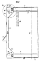
- side parts (5) are provided, of which only the left side part (5) is shown in FIG. 1, which shows only about half of the entire water / air cooler .
- these side parts (5) are made of steel, but they can also consist of another metal or of a plastic with sufficient stability, in particular of a plastic which is provided in a known manner with reinforcing inserts.
- Both side parts (5) are arranged symmetrically to the central axis (6) of the cooler and, as indicated in FIG. 1, are provided with fastening devices, as indicated for example at (7).
- the fastening device (7) consists of a fastening bracket which forms a support surface which can then be supported on part of the frame structure of the commercial vehicle, not shown.
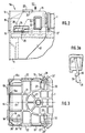
- the side part (5) - as well as the symmetrical side part on the other side - is provided at the upper and lower end with fastening tabs (12 and 13) which laterally overlap the upper water tank (1) and the lower water tank (2).
- the fastening tabs (12 and 13) each consist of two tab parts (12, 12a - and 13, 13a) which overlap the water boxes (1 and 2) on their front and rear sides, which can also be seen in FIG. 3.
- These fastening tabs (12, 12a) are part of a bow-shaped end (5a) which surrounds the end face of the water tank (1) in a U-shape, the web part (14) connecting the two tabs (12, 12a) to the upper edge (15) of the fastening tabs ( 12, 12a) completes.
- At least one opening is provided in the web part (14); in the exemplary embodiment, two openings (16, 16a) are provided which run symmetrically to the longitudinal center plane (17) of the water tank (1) and are dimensioned such that cam-like connecting pins (18) which are provided on the face of the water box (1) projecting outwards, reach into these openings (16, 16a) in a form-fitting manner. As can be seen in FIGS. 2 and 3, the free end of these connecting pins (18) only protrude slightly beyond the outer contour of the web part (14).
- connecting pins (19) are provided in the area of the tabs (12, 12a - 13 and 13a) on the front and rear, which in the exemplary embodiment have an approximately rectangular, Have cross-section similar to a pipe socket and, in the assembled state of the side parts (5) shown in FIGS. 2 and 3, positively engage in openings (20), likewise of rectangular cross-section.
- the connecting pins (19) are, like the connecting pins (18), attached in one piece to the water tank (1) made of plastic, which, as shown in FIG. 3, for manufacturing and stability reasons with rib-like stiffeners (21) on its top is provided. As is known per se, these stiffeners extend into the areas in which the connecting pins (18 and 19) are arranged.
- the fixed-case-side water tank (1) also has strips (22) which are fixed to it and laterally protrude from the upper side and which have guide surfaces (23) for the upper edge (15) of the fixing tabs (12) on their underside facing the fixing tabs (12 - or 13) - or 13) form.
- the fastening tabs (12 and 13) are provided in the area between their openings (20) and the web part (14) with rectangular windows (24) which, in the assembled state of the side parts, attached firmly to the sides of the water boxes (1 and 2) There are cams (25) which are provided with a run-up slope (26) on the side facing the front of the water tank (1 or 2).
- the dimensions of the ramp (26) and the cams (25) are chosen so that the free ends (12 'and 12a') of the fastening tabs (12 and 12a) - analogously (13 and 13a) - during assembly on the Water boxes (1 or 2) and in the case of the side sliding open for this purpose are spread apart, so far that during the side sliding on operation they are led with their free ends over the free ends of the connecting pins (19) can be.
- the upper edges (15) of the fastening tabs (12) can be placed on the guide surfaces (23) of the strips (22).
- the window (24) in the fastening tabs is designed so that it comes to rest in front of the cams (25) as soon as the free ends (12 ') are in the area of the fastening pins (19), so that the fastening tabs are on them Can connect connecting pins.
- each water tank (1 or 2) there are finally provided locking hooks (30) assigned to the two sides which, as shown in FIG. 3, with their hook-like end (30 ') the free end (12' or 12a ') of overlap assigned fastening tab in the assembled state.
- the locking hooks (30) are articulated at a point (27) on the water tank (1) or on one of its stiffeners, which is displaced further to the front side of the water tank (1 or 2) than the free end (12 'or 12a ') of the fastening tab (12 or 12a) in the fastened and pushed-on state, as can be clearly seen from FIG. 3.
- Each locking hook (30) also has at its free end a contact projection (28), the function of which will be discussed in the description of the assembly process.
- Fig. 3a shows that due to the arrangement of the articulation point (27), the elastic locking hooks (30), which of course preferably consist of the same plastic material as the water tank (1) and are molded directly, when a force (31) exerted on them, which tries to detach the fastening tabs (12, 12a) from the connecting pins (19), are also subjected to a force component (29) which presses the hook end of the latching hooks (30) towards the free end of the fastening tabs.
- a force component (29) which presses the hook end of the latching hooks (30) towards the free end of the fastening tabs.
- the selected configuration makes it easy to proceed in such a way that the side parts each with the outer edges (15) of their fastening tabs (12 or 12a) first from the outside on the guide surfaces (23) be created.
- the side parts (5) are then pushed onto the water boxes (1 or 2) with their fastening tabs (12, 13) perpendicular to the central longitudinal plane (6) of the finned tube block.
- the fastening tabs (12, 12a or 13, 13a) spread out through the run-up of their ends on the run-up bevels (26) and are held in this spread position when the free ends (12 ') are on the outer end faces of the connecting pins ( 19) hang up while the window (24) slides over the cams (25) and the run-up slopes (26).
- the free ends (12 ') abut the contact projections (28) of the latching hooks and press them towards the center of the water boxes into a prestressed position.
- the fastening tabs (12, 12a - or 13, 13a) snap onto the connecting pins (19) under their own tension, while the connecting pins (18) simultaneously reach their end position in the openings (16 ) in the web part (14).
- the free ends (12 ', 12a') of the fastening tabs release the contact projections (28) and the free end parts (30 ') of the latching hooks (30), so that they move into the securing position shown in FIG. 3 due to their Can swivel the preload back and attach to the mounting brackets from the outside.
- the assembly position is thus secured. As previously explained, this cannot be solved even when forces are exerted on the fastening tabs.
- the latching hooks (30) must first be pushed away from the end of the fastening straps, after which the fastening straps must be spread out before they are pulled off the water boxes again.
- the disassembly is therefore much more complex than the assembly, which, as explained, can be done by simply sliding it on without any tools.
Landscapes
- Engineering & Computer Science (AREA)
- Physics & Mathematics (AREA)
- Thermal Sciences (AREA)
- Mechanical Engineering (AREA)
- General Engineering & Computer Science (AREA)
- Air-Conditioning For Vehicles (AREA)
- Cooling, Air Intake And Gas Exhaust, And Fuel Tank Arrangements In Propulsion Units (AREA)
Description
Die Erfindung betrifft einen Wasser/Luft-Kühler für wassergekühlte Verbrennungskraftmaschinen, insbesondere von Nutzfahrzeugen, dessen Kühlerblock einschließlich der Wasserkästen, die insbesondere aus Kunststoff hergestellt sind, über Seitenteile befestigbar ist, die an ihren beiden Enden mit je zwei die Wasserkästen seitlich übergreifenden Befestigungslaschen versehen sind, die Teil eines die Stirnseite des zugeordneten Wasserkastens U-förmig übergreifenden bügelförmigen Endes der Seitenteile sind und Öffnungen aufweisen, durch die formschlüssig fest an den Querseiten der Wasserkästen angebrachte Verbindungszapfen greifen.The invention relates to a water / air cooler for water-cooled internal combustion engines, in particular commercial vehicles, the radiator block, including the water boxes, which are made in particular of plastic, can be fastened via side parts, which are provided at both ends with two fastening tabs laterally overlapping the water boxes , which are part of a U-shaped overlapping bow-shaped end of the side parts of the associated water box and have openings through which positively attached connecting pins on the transverse sides of the water boxes engage.
Wasser/Luft-Kühler dieser Art sind bekannt (DE 34 28 857 A1). Bei diesen bekannten Bauarten sind jedem seitlichen Ende des Wasserkastens auf jeder Seite je zwei der Verbindungszapfen zugeordnet, von denen der mehr zur Mitte des Wasserkastens gelegene Verbindungszapfen auch noch mit einer Sicherung gegen eine Wiederabnahme der Laschen versehen ist. Diese Sicherung kann dabei als eine Sicherungsfeder ausgebildet sein, die auf eine Nut des Verbindungszapfens aufgeschoben wird. Es ist aber auch möglich und vorgesehen, den Verbindungszapfen selbst aus dem elastischen Kunststoffmaterial des Wasserkastens zu formen und ihn an seinem freien Ende mit nachgiebigen Rasthaken zu versehen, die nach dem Aufschieben der Laschen die zugeordneten Öffnungen außen übergreifen. Bei der bekannten Bauart ist der mehr nach außen gelegene, diesem eben erwähnten Verbindungszapfen benachbarte Verbindungszapfen nur formschlüssig durch eine zugeordnete Öffnung gesteckt und mit einer Auflaufschräge versehen, die bei der Montage dazu dient, die parallelen Laschen seitlich so weit aufzuspreizen, daß sie über beide Verbindungszapfen bis zum Einschnappen derselben in die Öffnungen geschoben werden kann.Water / air coolers of this type are known (DE 34 28 857 A1). In these known designs, two lateral connecting pins are assigned to each side end of the water box on each side, of which the connecting pin located more towards the center of the water box is also provided with a safety device to prevent the tabs from being removed again. This fuse can be designed as a locking spring that is pushed onto a groove of the connecting pin. However, it is also possible and intended to form the connecting pin itself from the elastic plastic material of the water tank and to provide it at its free end with flexible latching hooks which overlap the associated openings on the outside after the tabs have been pushed open. In the known design, the connecting pin, which is located more to the outside and is adjacent to the connecting pin just mentioned, is only inserted in a form-fitting manner through an associated opening and with a run-up slope provided, which is used during assembly to spread the parallel tabs laterally so far that they can be pushed over both connecting pins until they snap into the openings.
Bei einer solchen Bauart ist die Montage nicht immer einfach, weil die Seitenteile gegenüber den Wasserkästen und dem Kühlerblock jeweils so geschwenkt werden müssen, daß die in den Laschen vorgesehenen Öffnungen auf die Verbindungsbolzen passen. Dazu kommt, daß der aus den Wasserkästen und den Seitenteilen aufgebaute Rahmen die beim Betrieb des Fahrzeuges auftretenden Verwindungskräfte nur über die beiden relativ eng zusammenliegenden Verbindungszapfen aufnehmen kann.With such a construction, assembly is not always easy because the side parts have to be pivoted relative to the water tanks and the radiator block in such a way that the openings provided in the tabs fit onto the connecting bolts. In addition, the frame constructed from the water boxes and the side parts can only absorb the torsional forces that occur during operation of the vehicle via the two relatively closely located connecting pins.
Der Erfindung liegt die Aufgabe zugrunde, einen Wasser/Luft-Kühler der eingangs genannten Art so auszubilden, daß bei einfacher Montagemöglichkeit die Stabilität des Rahmens, d.h. der Seitenteil/Wasserkastenverbindung erhöht wird.The invention has for its object to provide a water / air cooler of the type mentioned so that the stability of the frame, i. the side part / water box connection is increased.
Zur Lösung dieser Aufgabe wird bei einem Wasser/Luft-Kühler der eingangs genannten Art vorgesehen,, daß in dem die Befestigungslaschen verbindenden Stegteil mindestens eine Öffnung vorgesehen ist und daß die Wasserkästen jeweils an ihrer Stirnseite mit zumindest einem der Verbindungszapfen versehen sind, der formschlüssig durch die mindestens eine Öffnung in dem Stegteil greift.To solve this problem is provided in a water / air cooler of the type mentioned, that at least one opening is provided in the web part connecting the fastening tabs and that the water boxes are each provided on their front side with at least one of the connecting pins which form-fit which engages at least one opening in the web part.
Durch diese Ausgestaltung kann der maximal mögliche Abstand zwischen den am Wasserkasten fest angeordneten Verbindungszapfen verwirklicht werden, so daß die auf den Rahmen ausgeübten Verwindungskräfte bei gleichen Rahmenabmessungen zu kleineren Kräften zwischen Befestigungslaschen und Verbindungszapfen führen. Da die Befestigungslaschen außerdem eine Art U-Bügel bilden, der mit seinem Steg auch noch die Stirnseite des Wasserkastens übergreift, wird auch auf diese Art eine erhöhte Stabilität des so aus Wasserkästen und Seitenteilen gebildeten Rahmens erreicht.With this configuration, the maximum possible distance between the connecting pins fixedly arranged on the water tank can be realized, so that the torsional forces exerted on the frame, with the same frame dimensions, lead to smaller forces between fastening tabs and connecting pins. Since the mounting tabs also have a Form type U-bracket, which also overlaps the front of the water box with its web, an increased stability of the frame thus formed from water boxes and side parts is also achieved in this way.
Um die Montage zu erleichtern, ist es bei der erfindungsgemäßen Ausgestaltung, bei der die Oberkante der Befestigungslaschen in den Bereich des seitlichen oberen Abschlusses des Wasserkastens hereinragen, vorteilhaft möglich, an den Wasserkasten Führungsflächen zur Anlage an den Oberkanten der Befestigungslaschen vorzusehen. Bei der Montage, die wie beim Stand der Technik durch seitliches Aufschieben der Seitenteile mit ihren Befestigungslaschen geschieht, kann daher für eine Vorpositionierung der Befestigungslaschen während des Aufschiebevorganges gesorgt werden, so daß der Montagevorgang einfacher wird. Die Oberkanten und die Führungsflächen können dabei senkrecht zu den Seitenflächen der Seitenteile verlaufen, so daß auch auf diese Weise ein einfacher Ausrichtvorgang bei der Montage ermöglicht wird.To facilitate assembly, it is advantageously possible in the embodiment according to the invention, in which the upper edge of the fastening tabs protrude into the region of the lateral upper end of the water box, to provide guide surfaces on the water box for contact with the upper edges of the fastening tabs. During assembly, which, as in the prior art, is done by pushing the side parts on with their fastening tabs, the fastening tabs can be pre-positioned during the pushing-on process, so that the assembly process becomes easier. The upper edges and the guide surfaces can run perpendicular to the side surfaces of the side parts, so that a simple alignment process during assembly is also made possible in this way.
Um hier das notwendige Aufspreizen der Befestigungslaschen zu erreichen, kann es nach den Merkmalen des Anspruches 3 sehr vorteilhaft sein, dem Wasserkasten seitlich und im Bereich zwischen dem Verbindungszapfen und der Stirnseite des Wasserkastens mindestens eine Auflaufschräge zum Spreizen der seitlich aufschiebbaren Befestigungslaschen zuzuordnen, deren Wirkung nach den Merkmalen des Anspruches 4 dadurch wieder aufgehoben werden kann, daß die Befestigungslasche ein Fenster aufweist, das dann, wenn beim seitlichen Aufschieben der Befestigungslasche deren freies Ende auf dem freien Ende des Verbindungszapfens zur Auflage kommt, mit der Auflaufschräge zur Deckung kommt. Beim Montagevorgang gleitet dann die Befestigungslasche über den eigentlichen seitlichen Verbindungszapfen hinweg und schnappt dann aufgrund ihrer Elastizität über diesen, wenn sie sich mit ihrer Öffnung mit der Kontur des Verbindungszapfens deckt. Die Auflaufschräge befindet sich in dieser Endlage - und wie bereits ausgeführt auch schon vorher - im Bereich des Fensters.In order to achieve the necessary spreading of the fastening tabs here, it can be very advantageous, according to the features of claim 3, to assign at least one run-up slope to the side of the water box and in the area between the connecting pin and the end face of the water box for spreading the laterally push-on fastening tabs, the effect of which the features of claim 4 can be canceled by the fact that the fastening tab has a window which, when the free end of the fastening tab comes to rest on the free end of the connecting pin when the fastening tab is pushed on, comes to cover with the ramp. During the assembly process, the fastening tab then slides over the actual lateral connecting pin and then snaps over it due to its elasticity when it opens with the contour of Connecting pin covers. The run-up slope is in this end position - and as already mentioned before - in the area of the window.
Nach den Merkmalen des Anspruches 5 kann dem freien Ende der Befestigungslaschen mindestens ein Rasthaken zugeordnet sein, der das freie Ende der Befestigungslaschen außen übergreift, wenn die Öffnung der Befestigungslasche formschlüssig den Verbindungszapfen umgreift. Dieser Rasthaken kann nach Anspruch 6 ein elastisch am Wasserkasten angebrachter Schwenkteil sein, der vorzugsweise aus dem Kunststoffmaterial des Wasserkastens hergestellt ist und der nach Anspruch 7 an seinem freien Ende einen Anlagevorsprung aufweist, durch den der Rasthaken von dem noch im gespreizten Zustand befindlichen freien Ende der Befestigungslasche erfaßt und dadurch vorgespannt wird, daß er aus seiner ursprünglichen Lage nach hinten verschoben wird. Geht die Befestigungslasche nach dem Aufschiebevorgang aber in ihre Ausgangslage zurück, in der die beiden Befestigungslaschen parallel zueinander verlaufen, dann gibt das freie Ende der Befestigungslaschen den Anlagevorsprung frei und der Rasthaken kann unter seiner Vorspannung in seine Ausgangslage zurückschwenken, in der er dann mit seinem Haken die Außenseite der Befestigungslasche übergreift.According to the features of
Dabei ist es nach den Merkmalen des Anspruches 8 besonders vorteilhaft, wenn der Rasthaken an einer Stelle am Wasserkasten angelenkt ist, die weiter zur Stirnseite des Wasserkastens verlagert ist als das freie Ende der Befestigungslasche im aufgeschobenen Zustand der Befestigung am Wasserkasten. Durch diese Maßnahme nämlich wird dann, wenn von der Befestigungslasche aus Kräfte auf den Rasthaken ausgeübt werden, die ein Aufspreizen und damit ein mögliches Lösen der Befestigungslaschen bewirken könnten, auch eine Kraftkomponente bewirkt, die den Rasthaken in Richtung zur Befestigungslasche drückt, so daß ein unbeabsichtigtes Öffnen des als Sicherung dienenden Rasthakens nicht zu befürchten ist.It is particularly advantageous according to the features of claim 8 if the latching hook is articulated at a point on the water tank that is displaced further to the front of the water tank than the free end of the fastening tab in the pushed-on state of the fastening on the water tank. By this measure namely, when forces are exerted on the latching hook from the fastening tab, which could cause a spreading and thus a possible loosening of the fastening tabs, a force component is also caused which presses the latching hook towards the fastening tab, so that an unintentional There is no need to fear that the latching hook, which serves as a safeguard.
Die Erfindung ist anhand eines Ausführungsbeispieles in der Zeichnung dargestellt und wird im folgenden erläutert. Es zeigen:
- Fig. 1
- eine schematische Teilansicht eines erfindungsgemäß ausgestalteten Wasser/Luft-Kühlers,
- Fig. 2
- eine vergrößerte Darstellung der linken oberen Ecke des Wasser/Luft-Kühlers der Fig. 1 gemäß dem Detail II,
- Fig. 3
- die Draufsicht auf die Ecke des Wasser/Luft-Kühlers gemäß Fig. 2 in Richtung des Pfeiles III gesehen und
- Fig. 3a
- eine schematische Darstellung des Kraftverlaufes auf den Rasthaken der Fig. 3.
- Fig. 1
- 2 shows a schematic partial view of a water / air cooler designed according to the invention,
- Fig. 2
- 2 shows an enlarged illustration of the upper left corner of the water / air cooler of FIG. 1 according to detail II,
- Fig. 3
- seen the top view of the corner of the water / air cooler according to FIG. 2 in the direction of arrow III and
- Fig. 3a
- 3 shows a schematic illustration of the force curve on the latching hook of FIG. 3.
In der Fig. 1 ist ein Wasser/Luft-Kühler für ein Nutzfahrzeug dargestellt, der aus einem oberen, aus Kunststoff hergestellten Wasserkasten (1) und aus einem ebenfalls aus Kunststoff hergestellten unteren Wasserkasten (2) besteht, zwischen denen in bekannter Weise Rohre zur Führung des Kühlwassers angeordnet sind, von denen nur die Achsen (3) gezeigt sind. Die Rohrachsen (3) verlaufen senkrecht zu den Befestigungsflanschen (4) der Wasserkästen (1 und 2). Diese Rohre sind in bekannter Weise mit Rippen versehen und bilden mit den nicht gezeigten Rohrböden einen Rippenrohrblock, der durch eine Lötverbindung hergestellt ist. Die Rohrböden sind mit dem zugeordneten Flansch (4) der Waserkästen (1 bzw. 2) verbördelt, wie das ebenfalls bekannt ist.In Fig. 1, a water / air cooler for a commercial vehicle is shown, which consists of an upper, made of plastic water box (1) and also made of plastic lower water box (2), between which in a known manner pipes for Guide the cooling water are arranged, of which only the axes (3) are shown. The pipe axes (3) run perpendicular to the mounting flanges (4) of the water boxes (1 and 2). These tubes are provided with fins in a known manner and, together with the tube sheets (not shown), form a finned tube block which is produced by a soldered connection. The tube sheets are crimped to the associated flange (4) of the water boxes (1 or 2), as is also known.
Um den Wasser/Luft-Kühler im Fahrzeug zu befestigen, sind Seitenteile (5) vorgesehen, von denen in der Fig. 1, die nur etwa die Hälfte des gesamten Wasser/Luft-Kühlers zeigt, nur das linke Seitenteil (5) gezeigt ist. Diese Seitenteile (5) bestehen beim Ausführungsbeispiel aus Stahl, sie können aber auch aus einem anderen Metall oder auch aus einem Kunststoff mit genügender Stabilität bestehen, insbesondere aus einem Kunststoff, der in bekannter Weise mit Verstärkungseinlagen versehen ist.In order to fix the water / air cooler in the vehicle, side parts (5) are provided, of which only the left side part (5) is shown in FIG. 1, which shows only about half of the entire water / air cooler . In the exemplary embodiment, these side parts (5) are made of steel, but they can also consist of another metal or of a plastic with sufficient stability, in particular of a plastic which is provided in a known manner with reinforcing inserts.
Beide Seitenteile (5) sind symmetrisch zur der Mittelachse (6) des Kühlers angeordnet und sind, wie in Fig. 1 angedeutet ist, mit Befestigungseinrichtungen, wie beispielsweise bei (7) angedeutet, versehen. Die Befestigungseinrichtung (7) besteht aus einem Befestigungswinkel, der eine Abstützfläche bildet, die dann auf einem Teil der Rahmenkonstruktion des nicht gezeigten Nutzfahrzeuges abstützbar ist.Both side parts (5) are arranged symmetrically to the central axis (6) of the cooler and, as indicated in FIG. 1, are provided with fastening devices, as indicated for example at (7). The fastening device (7) consists of a fastening bracket which forms a support surface which can then be supported on part of the frame structure of the commercial vehicle, not shown.
Das Seitenteil (5) - ebenso das symmetrische Seitenteil auf der anderen Seite - ist am oberen und unteren Ende mit Befestigungslaschen (12 und 13) versehen, die den oberen Wasserkasten (1) und den unteren Wasserkasten (2) seitlich übergreifen. Die Befestigungslaschen (12 und 13) bestehen jeweils aus zwei die Wasserkästen (1 bzw. 2) auf ihrer Vorder- und Rückseite übergreifenden Laschenteilen (12, 12a - bzw. 13, 13a), die in der Fig. 3 auch zu erkennen sind. Diese Befestigungslaschen (12, 12a) sind Teil eines die Stirnseite des Wasserkastens (1) U-förmig umgreifenden bügelförmigen Endes (5a), dessen die beiden Laschen (12, 12a) verbindender Stegteil (14) mit der Oberkante (15) der Befestigungslaschen (12, 12a) abschließt. In dem Stegteil (14) ist mindestens eine Öffnung, beim Ausführungsbeispiel sind zwei Öffnungen (16, 16a) vorgesehen, die symmetrisch zu der Längsmittelebene (17) des Wasserkastens (1) verlaufen und so bemessen sind, daß nockenartige Verbindungszapfen (18), die an der Stirnseite des Wasserkastens (1) nach außen abstehend vorgesehen sind, formschlüssig in diese Öffnungen (16, 16a) hereingreifen. Wie den Fig. 2 und 3 zu entnehmen ist, stehen diese Verbindungszapfen (18) mit ihrem freien Ende nur etwas über die Außenkontur des Stegteiles (14) über.The side part (5) - as well as the symmetrical side part on the other side - is provided at the upper and lower end with fastening tabs (12 and 13) which laterally overlap the upper water tank (1) and the lower water tank (2). The fastening tabs (12 and 13) each consist of two tab parts (12, 12a - and 13, 13a) which overlap the water boxes (1 and 2) on their front and rear sides, which can also be seen in FIG. 3. These fastening tabs (12, 12a) are part of a bow-shaped end (5a) which surrounds the end face of the water tank (1) in a U-shape, the web part (14) connecting the two tabs (12, 12a) to the upper edge (15) of the fastening tabs ( 12, 12a) completes. At least one opening is provided in the web part (14); in the exemplary embodiment, two openings (16, 16a) are provided which run symmetrically to the longitudinal center plane (17) of the water tank (1) and are dimensioned such that cam-like connecting pins (18) which are provided on the face of the water box (1) projecting outwards, reach into these openings (16, 16a) in a form-fitting manner. As can be seen in FIGS. 2 and 3, the free end of these connecting pins (18) only protrude slightly beyond the outer contour of the web part (14).
An dem Wasserkasten (1) - und analog natürlich am Wasserkasten (2) - sind im Bereich der Laschen (12, 12a - 13 und 13a) jeweils auf der Vorder- und Rückseite Verbindungszapfen (19) vorgesehen, die beim Ausführungsbeispiel einen etwa rechteckigen, rohrstutzenähnlichen Querschnitt aufweisen und die in dem in den Fig. 2 und 3 gezeigten montierten Zustand der Seitenteile (5) formschlüssig in Öffnungen (20), ebenfalls von rechteckigem Querschnitt, eingreifen. Die Verbindungszapfen (19) sind ebenso wie die Verbindungszapfen (18) einstückig an dem aus Kunststoff hergestellten Wasserkasten (1) angebracht, der im übrigen, wie Fig. 3 zeigt, aus Herstellungs- und Stabilitätsgründen mit rippenartig angeordneten Versteifungen (21) an seiner Oberseite versehen ist. Diese Versteifungen sind, wie an sich bekannt ist, bis in die Bereiche geführt, in denen die Verbindungszapfen (18 bzw. 19) angeordnet sind.On the water tank (1) - and of course analogously on the water tank (2) - connecting pins (19) are provided in the area of the tabs (12, 12a - 13 and 13a) on the front and rear, which in the exemplary embodiment have an approximately rectangular, Have cross-section similar to a pipe socket and, in the assembled state of the side parts (5) shown in FIGS. 2 and 3, positively engage in openings (20), likewise of rectangular cross-section. The connecting pins (19) are, like the connecting pins (18), attached in one piece to the water tank (1) made of plastic, which, as shown in FIG. 3, for manufacturing and stability reasons with rib-like stiffeners (21) on its top is provided. As is known per se, these stiffeners extend into the areas in which the connecting pins (18 and 19) are arranged.
Der festlagerseitige Wasserkasten (1) besitzt außerdem fest an ihm angeordnete von der Oberseite seitlich abstehende Leisten (22), die auf ihrer den Befestigungslaschen (12 - bzw. 13) zugewandten Unterseite Führungsflächen (23) für die Oberkante (15) der Befestigungslaschen (12 - bzw. 13) bilden.The fixed-case-side water tank (1) also has strips (22) which are fixed to it and laterally protrude from the upper side and which have guide surfaces (23) for the upper edge (15) of the fixing tabs (12) on their underside facing the fixing tabs (12 - or 13) - or 13) form.
Die Befestigungslaschen (12 und 13) sind im Bereich zwischen ihren Öffnungen (20) und dem Stegteil (14) mit rechteckigen Fenstern (24) versehen, die im montierten Zustand der Seitenteile vor fest an den Seiten der Wasserkästen (1 bzw. 2) angebrachen Nocken (25) liegen, die auf der zur Stirnseite des Wasserkastens (1 bzw. 2) gerichteten Seite mit einer Auflaufschräge (26) versehen sind. Die Abmessungen der Auflaufschräge (26) und der Nocken (25) ist dabei so gewählt, daß die freien Enden (12' bzw. 12a') der Befestigungslaschen (12 und 12a) - analog (13 und 13a) - bei der Montage an den Wasserkästen (1 bzw. 2) und bei dem zu diesem Zweck erfolgenden seitlichen Aufschieben auseinandergespreizt werden, und zwar so weit, daß sie bei dem seitlichen Aufschiebevorgang mit ihren freien Enden über die freien Enden der Verbindungszapfen (19) hinweggeführt werden können. Während dieses Aufschiebevorganges können die Oberkanten (15) der Befestigungslaschen (12) an den Führungsflächen (23) der Leisten (22) angelegt werden. Das Fenster (24) in den Befestigungslaschen ist dabei so ausgelegt, daß es vor den Nocken (25) zu liegen kommt, sobald die freien Enden (12') sich im Bereich der Befestigungszapfen (19) befinden, so daß sich die Befestigungslaschen auf diesen Verbindungszapfen auflegen können.The fastening tabs (12 and 13) are provided in the area between their openings (20) and the web part (14) with rectangular windows (24) which, in the assembled state of the side parts, attached firmly to the sides of the water boxes (1 and 2) There are cams (25) which are provided with a run-up slope (26) on the side facing the front of the water tank (1 or 2). The dimensions of the ramp (26) and the cams (25) are chosen so that the free ends (12 'and 12a') of the fastening tabs (12 and 12a) - analogously (13 and 13a) - during assembly on the Water boxes (1 or 2) and in the case of the side sliding open for this purpose are spread apart, so far that during the side sliding on operation they are led with their free ends over the free ends of the connecting pins (19) can be. During this pushing-on process, the upper edges (15) of the fastening tabs (12) can be placed on the guide surfaces (23) of the strips (22). The window (24) in the fastening tabs is designed so that it comes to rest in front of the cams (25) as soon as the free ends (12 ') are in the area of the fastening pins (19), so that the fastening tabs are on them Can connect connecting pins.
An jedem Wasserkasten (1 bzw. 2) sind schließlich noch den beiden Seiten zugeordnete Rasthaken (30) vorgesehen, die, wie Fig. 3 zeigt, mit ihrem hakenartigen Ende (30') das freie Ende (12' bzw. 12a') der zugeordneten Befestigungslasche im montierten Zustand übergreifen. Die Rasthaken (30) sind dabei an einer Stelle (27) am Wasserkasten (1) bzw. an einer seiner Versteifungen angelenkt, die weiter zur Stirnseite des Wasserkastens (1 bzw. 2) verlagert ist, als das freie Ende (12' bzw. 12a') der Befestigungslasche (12 bzw. 12a) im befestigten und aufgeschobenen Zustand, wie das aus Fig. 3 deutlich zu erkennen ist. Jeder Rasthaken (30) besitzt außerdem an seinem freien Ende einen Anlagevorsprung (28), auf dessen Funktion bei der Schilderung des Montagevorganges noch eingegangen werden wird.On each water tank (1 or 2) there are finally provided locking hooks (30) assigned to the two sides which, as shown in FIG. 3, with their hook-like end (30 ') the free end (12' or 12a ') of overlap assigned fastening tab in the assembled state. The locking hooks (30) are articulated at a point (27) on the water tank (1) or on one of its stiffeners, which is displaced further to the front side of the water tank (1 or 2) than the free end (12 'or 12a ') of the fastening tab (12 or 12a) in the fastened and pushed-on state, as can be clearly seen from FIG. 3. Each locking hook (30) also has at its free end a contact projection (28), the function of which will be discussed in the description of the assembly process.
Die Fig. 3a läßt erkennen, daß aufgrund der Anordnung der Anlenkungsstelle (27) die elastischen Rasthaken (30), die vorzugsweise natürlich aus demselben Kunststoffmaterial wie der Wasserkasten (1) bestehen und unmittelbar mit angespritzt sind, dann, wenn eine Kraft (31) auf sie ausgeübt wird, die versucht, die Befestigungslaschen (12, 12a) von den Verbindungszapfen (19) zu lösen, auch einer Kraftkomponente (29) ausgesetzt werden, die das Hakenende der Rasthaken (30) in Richtung zum freien Ende der Befestigungslaschen drückt. Ein unfreiwilliges Lösen der Befestigungslaschen aus der in den Fig. 2 und 3 gezeigten Montagestellung ist daher nicht möglich.Fig. 3a shows that due to the arrangement of the articulation point (27), the elastic locking hooks (30), which of course preferably consist of the same plastic material as the water tank (1) and are molded directly, when a force (31) exerted on them, which tries to detach the fastening tabs (12, 12a) from the connecting pins (19), are also subjected to a force component (29) which presses the hook end of the latching hooks (30) towards the free end of the fastening tabs. An involuntary loosening of the fastening tabs from the mounting position shown in FIGS. 2 and 3 is therefore not possible.
Bei der Montage der Seitenteile (5) an dem Rippenrohrblock kann aufgrund der gewählten Ausgestaltung in einfacher Weise so vorgegangen werden, daß die Seitenteile jeweils mit den Außenkanten (15) ihrer Befestigungslaschen (12 bzw. 12a) zunächst von außen an den Führungsflächen (23) angelegt werden. Die Seitenteile (5) werden dann mit ihren Befestigungslaschen (12, 13) senkrecht zur Mittellängsebene (6) des Rippenrohrblockes auf die Wasserkästen (1 bzw. 2) aufgeschoben. Die Befestigungslaschen (12, 12a bzw. 13, 13a) spreizen sich dabei durch das Auflaufen ihrer Enden auf den Auflaufschrägen (26) und werden in dieser gespreizten Stellung gehalten, wenn die freien Ende (12') sich auf die äußeren Stirnseiten der Verbindungszapfen (19) auflegen, während das Fenster (24) sich über die Nocken (25) und die Auflaufschrägen (26) schiebt. Beim weiteren Aufschieben stoßen die freien Enden (12') an den Anlagevorsprüngen (28) der Rasthaken an und drücken diese in Richtung auf die Mitte der Wasserkästen in eine vorgespannte Stellung. Erreicht die Öffnung (20) nun ihre Endstellung, dann schnappen die Befestigungslaschen (12, 12a - bzw. 13, 13a) unter ihrer Eigenspannung auf die Verbindungszapfen (19) auf, während gleichzeitig die Verbindungszapfen (18) ihre Endposition in den Öffnungen (16) im Stegteil (14) einnehmen. Beim nach Innenschnappen geben die freien Enden (12', 12a') der Befestigungslaschen die Anlagevorsprünge (28) und die freien Endteile (30') der Rasthaken (30) frei, so daß diese in die in der Fig. 3 gezeigte Sicherungsposition aufgrund ihrer Vorspannung zurückschwenken können und sich von außen an die Befestigungslaschen anlegen. Die Montagestellung ist damit gesichert. Wie vorher erläutert wurde, ist diese auch bei Ausübung von Kräften auf die Befestigungslaschen nicht zu lösen. Für eine Demontage müssen vielmehr die Rasthaken (30) zunächst vom Ende der Befestigungslaschen weggedrückt werden, wonach das Spreizen der Befestigungslaschen erfolgen muß, ehe diese wieder von den Wasserkästen abgezogen werden. Die Demontage ist daher wesentlich aufwendiger als die Montage, die, wie erläutert, ohne jedes Werkzeug lediglich durch Aufschieben erfolgen kann.When assembling the side parts (5) on the finned tube block, the selected configuration makes it easy to proceed in such a way that the side parts each with the outer edges (15) of their fastening tabs (12 or 12a) first from the outside on the guide surfaces (23) be created. The side parts (5) are then pushed onto the water boxes (1 or 2) with their fastening tabs (12, 13) perpendicular to the central longitudinal plane (6) of the finned tube block. The fastening tabs (12, 12a or 13, 13a) spread out through the run-up of their ends on the run-up bevels (26) and are held in this spread position when the free ends (12 ') are on the outer end faces of the connecting pins ( 19) hang up while the window (24) slides over the cams (25) and the run-up slopes (26). When pushed on further, the free ends (12 ') abut the contact projections (28) of the latching hooks and press them towards the center of the water boxes into a prestressed position. If the opening (20) now reaches its end position, the fastening tabs (12, 12a - or 13, 13a) snap onto the connecting pins (19) under their own tension, while the connecting pins (18) simultaneously reach their end position in the openings (16 ) in the web part (14). When snapping inwards, the free ends (12 ', 12a') of the fastening tabs release the contact projections (28) and the free end parts (30 ') of the latching hooks (30), so that they move into the securing position shown in FIG. 3 due to their Can swivel the preload back and attach to the mounting brackets from the outside. The assembly position is thus secured. As previously explained, this cannot be solved even when forces are exerted on the fastening tabs. For disassembly, the latching hooks (30) must first be pushed away from the end of the fastening straps, after which the fastening straps must be spread out before they are pulled off the water boxes again. The disassembly is therefore much more complex than the assembly, which, as explained, can be done by simply sliding it on without any tools.
Claims (9)
- A water/air radiator for water-cooled internal combustion engines, particularly of utility vehicles, of which the radiator block including the water tanks, particularly a block which is made from synthetic plastics material, can be mounted via side parts (5) which are provided at both ends with fixing lugs (12, 12a, 13) engaging laterally over the water tanks (1, 2) and part of a stirrup-shaped end (5a) of the side parts (5) which engage over the end face of the associated water tank (1 or 2) and have apertures (20) through which engage connecting studs (19) mounted rigidly and in form-locking fashion on the transverse sides of the water tanks, characterised in that at least one aperture (16) is provided in the web part (14) connecting the fixing lugs and in that the water tanks (1, 2) are provided on their end face with at least one connecting stud (18) which engages in form-locking manner through the at least one aperture (16) in the web part (14).
- A water/air radiator according to Claim 1, characterised in that on the water tank (1) there is at least one guide surface (23) intended to bear on the top edge (15) of the fixing lugs (12, 12a).
- A water/air radiator according to Claim 1, characterised in that for spreading apart the fixing lugs (12, 12, 13) which can be pushed on laterally, at least one ramp (26) is associated with the water tanks (1, 2) laterally and in the region between lateral connecting studs (19) and the end face.
- A water/air radiator according to Claim 3, characterised in that each fixing lug (12, 12a) has a window (24) which coincides with the ramp (26) when, upon the fixing lugs being pushed on laterally, the free end (12', 12a') bears on the free end of the lateral connecting stud (19).
- A water/air radiator according to one of Claims 1 to 4, characterised in that associated with the free ends (12', 12a') of the fixing lugs (12, 12a) is at least one catch hook (30) which engages over the outside of the free end of the fixing lug when the aperture (20) in the fixing lug engages in form-locking manner over the lateral connecting stud (19).
- A water/air radiator according to Claim 5, characterised in that the catch hook (30) is constructed as a pivotable part mounted resiliently on the water tank (1, 2).
- A water/air radiator according to Claim 6, characterised in that the pivot part has at the free end a projection (28) by which the catch hook (30) can be pre-tensioned by the still opened out free end of the fixing lug (12, 12a).
- A water/air radiator according to Claim 6 or 7, characterised in that the catch hook (30) is articulated at a position (27) on the water tank (1 or 2) which is shifted farther towards the end face of the water tank than the free end (12', 12a') of the fixing lugs (12, 12a) in the pushed-on and assembled state.
- A water/air radiator according to one of Claims 6 to 8, characterised in that the catch hook (30) is injection moulded in one piece on the water tank (1, 2) which is produced from synthetic plastics material.
Applications Claiming Priority (2)
| Application Number | Priority Date | Filing Date | Title |
|---|---|---|---|
| DE4109284 | 1991-03-21 | ||
| DE4109284A DE4109284A1 (en) | 1991-03-21 | 1991-03-21 | WATER / AIR COOLER FOR WATER-COOLED COMBUSTION ENGINES |
Publications (2)
| Publication Number | Publication Date |
|---|---|
| EP0504635A1 EP0504635A1 (en) | 1992-09-23 |
| EP0504635B1 true EP0504635B1 (en) | 1994-02-02 |
Family
ID=6427888
Family Applications (1)
| Application Number | Title | Priority Date | Filing Date |
|---|---|---|---|
| EP92103308A Expired - Lifetime EP0504635B1 (en) | 1991-03-21 | 1992-02-27 | Water/air radiator for watercooled internal combustion engine |
Country Status (3)
| Country | Link |
|---|---|
| EP (1) | EP0504635B1 (en) |
| DE (2) | DE4109284A1 (en) |
| ES (1) | ES2048602T3 (en) |
Cited By (2)
| Publication number | Priority date | Publication date | Assignee | Title |
|---|---|---|---|---|
| CN103327797A (en) * | 2013-07-05 | 2013-09-25 | 河南省法斯特散热器有限公司 | Horizontal water tank radiator |
| CN103327796A (en) * | 2013-07-05 | 2013-09-25 | 河南省法斯特散热器有限公司 | Water radiator arranged on mobile power supply unit in matching manner |
Families Citing this family (11)
| Publication number | Priority date | Publication date | Assignee | Title |
|---|---|---|---|---|
| FR2697907B1 (en) * | 1992-11-09 | 1995-01-20 | Valeo Thermique Moteur Sa | Heat exchanger with water boxes connected by uprights, especially for motor vehicles. |
| DE4243204C2 (en) * | 1992-12-19 | 1995-10-26 | Behr Gmbh & Co | Water-air cooler for water-cooled internal combustion engines |
| FR2706994A1 (en) * | 1993-06-24 | 1994-12-30 | Valeo Thermique Moteur Sa | Heat exchanger with water (header) boxes connected by uprights |
| DE4332919B4 (en) * | 1993-09-28 | 2007-02-22 | Valeo Gmbh | Radiator with intercooler |
| US5875907A (en) * | 1997-06-17 | 1999-03-02 | Aptargroup, Inc. | Tamper-evident dispensing closure for a container |
| DE29712351U1 (en) * | 1997-07-12 | 1997-09-11 | Behr GmbH & Co., 70469 Stuttgart | Heat exchanger arrangement with two heat exchangers |
| DE19824700A1 (en) * | 1998-06-03 | 1999-12-09 | Behr Gmbh & Co | Motor vehicle radiator design |
| DE19844048B4 (en) * | 1998-09-25 | 2012-02-02 | Behr Gmbh & Co. Kg | Heat exchanger, in particular for motor vehicles |
| DE29822378U1 (en) | 1998-12-16 | 1999-02-25 | Längerer & Reich GmbH, 70794 Filderstadt | Water / air cooler |
| FR2793012B1 (en) * | 1999-04-29 | 2001-07-27 | Valeo Thermique Moteur Sa | HEAT EXCHANGER HAVING FLEXIBLE TUBES, PARTICULARLY FOR A MOTOR VEHICLE |
| US6513579B1 (en) * | 2001-09-27 | 2003-02-04 | Delphi Technologies, Inc. | Post braze heat exchanger mounting and support brackets |
Family Cites Families (6)
| Publication number | Priority date | Publication date | Assignee | Title |
|---|---|---|---|---|
| US4230176A (en) * | 1978-04-24 | 1980-10-28 | Caterpillar Tractor Co. | Floating radiator tank top |
| US4382464A (en) * | 1981-08-12 | 1983-05-10 | Ex-Cell-O Corporation | Radiator |
| DE3303986A1 (en) * | 1983-02-05 | 1984-08-09 | Süddeutsche Kühlerfabrik Julius Fr. Behr GmbH & Co KG, 7000 Stuttgart | WATER / AIR COOLER FOR WATER-COOLED COMBUSTION ENGINES, ESPECIALLY COMMERCIAL VEHICLES |
| DE3428857A1 (en) * | 1984-08-04 | 1986-02-13 | Süddeutsche Kühlerfabrik Julius Fr. Behr GmbH & Co KG, 7000 Stuttgart | WATER / AIR COOLER FOR WATER-COOLED COMBUSTION ENGINES |
| DE3536457A1 (en) * | 1985-10-12 | 1987-06-25 | Sueddeutsche Kuehler Behr | HEAT EXCHANGER, ESPECIALLY RADIATOR FOR MOTOR VEHICLES |
| DE3820623A1 (en) * | 1988-06-17 | 1989-12-21 | Sueddeutsche Kuehler Behr | WATER / AIR COOLER FOR WATER-COOLED COMBUSTION ENGINES, ESPECIALLY COMMERCIAL VEHICLES |
-
1991
- 1991-03-21 DE DE4109284A patent/DE4109284A1/en not_active Withdrawn
-
1992
- 1992-02-27 DE DE92103308T patent/DE59200060D1/en not_active Expired - Lifetime
- 1992-02-27 EP EP92103308A patent/EP0504635B1/en not_active Expired - Lifetime
- 1992-02-27 ES ES92103308T patent/ES2048602T3/en not_active Expired - Lifetime
Cited By (4)
| Publication number | Priority date | Publication date | Assignee | Title |
|---|---|---|---|---|
| CN103327797A (en) * | 2013-07-05 | 2013-09-25 | 河南省法斯特散热器有限公司 | Horizontal water tank radiator |
| CN103327796A (en) * | 2013-07-05 | 2013-09-25 | 河南省法斯特散热器有限公司 | Water radiator arranged on mobile power supply unit in matching manner |
| CN103327796B (en) * | 2013-07-05 | 2015-09-02 | 河南省法斯特散热器有限公司 | The water radiator of supporting installation on a kind of power supply unit that flows |
| CN103327797B (en) * | 2013-07-05 | 2016-03-30 | 河南省法斯特散热器有限公司 | A kind of horizontal water tank radiator |
Also Published As
| Publication number | Publication date |
|---|---|
| DE59200060D1 (en) | 1994-03-17 |
| ES2048602T3 (en) | 1994-03-16 |
| EP0504635A1 (en) | 1992-09-23 |
| DE4109284A1 (en) | 1992-09-24 |
Similar Documents
| Publication | Publication Date | Title |
|---|---|---|
| EP0170952B1 (en) | Water/air radiator for a water-cooled combustion engine | |
| EP0401571B1 (en) | Heat-exchanger for cooling the cooling water and the charging air of an internal-combustion engine | |
| EP0504635B1 (en) | Water/air radiator for watercooled internal combustion engine | |
| DE2449045C3 (en) | Arrangement for connecting the tube plates, the side parts and the water tank of a heat exchanger | |
| EP3488498B1 (en) | Retaining frame assembly having main frame and securing element and fitting method | |
| DE19953787B4 (en) | Arrangement for connecting two heat exchangers | |
| EP0219021A2 (en) | Heat exchanger, particularly a cooler for motor vehicles | |
| DE4244037C2 (en) | Cooling unit for an internal combustion engine | |
| DE102017108432A1 (en) | Holding frame for a connector and method of assembly | |
| DE29707571U1 (en) | Arrangement for connecting two heat exchangers | |
| EP3452667B1 (en) | Gutter for surface drainage with an end wall | |
| DE3744644A1 (en) | Device for fastening a fan cowl to the waterbox of an air/water radiator for motor vehicles | |
| DE4244039C2 (en) | Cooling module for internal combustion engines | |
| EP1439364A1 (en) | Bracket for heat exchanger | |
| EP0299187B1 (en) | Plastic supporting chain for energy carriers | |
| EP0280107A1 (en) | Water-air cooler | |
| DE3907926A1 (en) | Heat exchanger, in particular a radiator for commercial (utility) vehicles | |
| DE1939135C3 (en) | Water coolers for automobiles, earth moving machines and the like | |
| EP0401590B1 (en) | Heat exchanger | |
| EP0932010B1 (en) | Heat exchanger | |
| DE19953786B4 (en) | Coolant cooler with a surge tank | |
| DE4041671A1 (en) | Heat exchanger unit - has tube ends widened, extending over tube floor, with sealing mat between water tank and tube floor | |
| DE3222301A1 (en) | Radiator, preferably for an internal-combustion engine | |
| DE3527054A1 (en) | Heat exchanger, in particular radiator/air cooler for internal combustion engines | |
| EP1225092B1 (en) | Motor car mirror |
Legal Events
| Date | Code | Title | Description |
|---|---|---|---|
| PUAI | Public reference made under article 153(3) epc to a published international application that has entered the european phase |
Free format text: ORIGINAL CODE: 0009012 |
|
| AK | Designated contracting states |
Kind code of ref document: A1 Designated state(s): DE ES FR GB IT SE |
|
| 17P | Request for examination filed |
Effective date: 19921016 |
|
| 17Q | First examination report despatched |
Effective date: 19930204 |
|
| GRAA | (expected) grant |
Free format text: ORIGINAL CODE: 0009210 |
|
| AK | Designated contracting states |
Kind code of ref document: B1 Designated state(s): DE ES FR GB IT SE |
|
| ITF | It: translation for a ep patent filed | ||
| REG | Reference to a national code |
Ref country code: ES Ref legal event code: FG2A Ref document number: 2048602 Country of ref document: ES Kind code of ref document: T3 |
|
| REF | Corresponds to: |
Ref document number: 59200060 Country of ref document: DE Date of ref document: 19940317 |
|
| GBT | Gb: translation of ep patent filed (gb section 77(6)(a)/1977) |
Effective date: 19940323 |
|
| ET | Fr: translation filed | ||
| PLBE | No opposition filed within time limit |
Free format text: ORIGINAL CODE: 0009261 |
|
| STAA | Information on the status of an ep patent application or granted ep patent |
Free format text: STATUS: NO OPPOSITION FILED WITHIN TIME LIMIT |
|
| 26N | No opposition filed | ||
| EAL | Se: european patent in force in sweden |
Ref document number: 92103308.0 |
|
| PGFP | Annual fee paid to national office [announced via postgrant information from national office to epo] |
Ref country code: GB Payment date: 19980121 Year of fee payment: 7 |
|
| PGFP | Annual fee paid to national office [announced via postgrant information from national office to epo] |
Ref country code: ES Payment date: 19980219 Year of fee payment: 7 |
|
| PG25 | Lapsed in a contracting state [announced via postgrant information from national office to epo] |
Ref country code: GB Free format text: LAPSE BECAUSE OF NON-PAYMENT OF DUE FEES Effective date: 19990227 |
|
| PG25 | Lapsed in a contracting state [announced via postgrant information from national office to epo] |
Ref country code: ES Free format text: LAPSE BECAUSE OF EXPIRATION OF PROTECTION Effective date: 19990301 |
|
| GBPC | Gb: european patent ceased through non-payment of renewal fee |
Effective date: 19990227 |
|
| REG | Reference to a national code |
Ref country code: ES Ref legal event code: FD2A Effective date: 20010601 |
|
| PG25 | Lapsed in a contracting state [announced via postgrant information from national office to epo] |
Ref country code: IT Free format text: LAPSE BECAUSE OF NON-PAYMENT OF DUE FEES Effective date: 20050227 |
|
| PGFP | Annual fee paid to national office [announced via postgrant information from national office to epo] |
Ref country code: SE Payment date: 20080219 Year of fee payment: 17 |
|
| PGFP | Annual fee paid to national office [announced via postgrant information from national office to epo] |
Ref country code: FR Payment date: 20080215 Year of fee payment: 17 |
|
| EUG | Se: european patent has lapsed | ||
| REG | Reference to a national code |
Ref country code: FR Ref legal event code: ST Effective date: 20091030 |
|
| PG25 | Lapsed in a contracting state [announced via postgrant information from national office to epo] |
Ref country code: FR Free format text: LAPSE BECAUSE OF NON-PAYMENT OF DUE FEES Effective date: 20090302 |
|
| PGFP | Annual fee paid to national office [announced via postgrant information from national office to epo] |
Ref country code: DE Payment date: 20100308 Year of fee payment: 19 |
|
| PG25 | Lapsed in a contracting state [announced via postgrant information from national office to epo] |
Ref country code: SE Free format text: LAPSE BECAUSE OF NON-PAYMENT OF DUE FEES Effective date: 20090228 |
|
| REG | Reference to a national code |
Ref country code: DE Ref legal event code: R119 Ref document number: 59200060 Country of ref document: DE Effective date: 20110901 |
|
| PG25 | Lapsed in a contracting state [announced via postgrant information from national office to epo] |
Ref country code: DE Free format text: LAPSE BECAUSE OF NON-PAYMENT OF DUE FEES Effective date: 20110901 |